Santerno sinus M User Manual
Variable frequency drive
Hide thumbs
Also See for sinus M:
- Installation instructions manual (16 pages) ,
- User manual (20 pages)
Table of Contents
Advertisement
• This manual is integrant and essential to the product. Carefully read the instructions contained herein as
they provide important hints for use and maintenance safety.
• This device is to be used only for the purposes it has been designed to. Other uses should be considered
improper and dangerous. The manufacturer is not responsible for possible damages caused by improper,
erroneous and irrational uses.
• Elettronica Santerno is responsible for the device in its original setting.
• Any changes to the structure or operating cycle of the device must be performed or authorized by the
Engineering Department of Elettronica Santerno.
• Elettronica Santerno assumes no responsibility for the consequences resulting by the use of non-original
spare-parts.
• Elettronica Santerno reserves the right to make any technical changes to this manual and to the device
without prior notice. If printing errors or similar are detected, the corrections will be included in the new
releases of the manual.
• Elettronica Santerno is responsible for the information contained in the original version of the Italian
manual.
• The information contained herein is the property of Elettronica Santerno and cannot be reproduced.
Elettronica Santerno enforces its rights on the drawings and catalogues according to the law.
SINUS M
VARIABLE FREQUENCY DRIVE
USER MANUAL
-Installation and Programming
Issued on
17/02/11
R.03.1
SW Ver. EU2.3
Elettronica Santerno S.p.A.
Strada Statale Selice, 47 - 40026 Imola (BO) Italy
Tel. +39 0542 489711 - Fax +39 0542 489722
santerno.com sales@santerno.com
•
•
15P0073B1
Instructions-
E n g l i s h
Advertisement
Table of Contents
Troubleshooting

Related Manuals for Santerno sinus M


Summary of Contents for Santerno sinus M
- Page 1 • Elettronica Santerno assumes no responsibility for the consequences resulting by the use of non-original spare-parts. • Elettronica Santerno reserves the right to make any technical changes to this manual and to the device without prior notice. If printing errors or similar are detected, the corrections will be included in the new releases of the manual.
- Page 2 Identifies shock hazard under certain conditions. Particular attention should be paid because dangerous voltage may be present. Keep operating instructions handy for quick reference. Read this manual carefully to maximize the performance of Sinus M series inverters and ensure safe usage. WARNING ...
- Page 3 Wiring and periodic inspections should be performed at least 10 minutes after disconnecting the input power and after checking the DC link voltage is discharged with a meter (below DC 30V). Otherwise, you may get an electric shock. Operate the switches with dry hands. Otherwise, you may get an electric shock.
- Page 4 Follow your national electrical code for grounding. Recommended Ground impedance for 2S/T class (200-230V) is below 100Ω and for 4T class (380-480V) below 10Ω. SINUS M series contains ESD (Electrostatic Discharge) sensitive parts. Take protective measures against ESD before touching the PCB for inspection or installation.
- Page 5 (4) Operation precautions When the Auto restart function is selected, stay away from the equipment as a motor will restart suddenly after an alarm stop. The Stop key on the keypad is valid only when the appropriate function setting has been ...
- Page 6 The purpose of this manual is to provide the user with the necessary information to install, program, start up and maintain the SINUS M series inverter. To assure successful installation and operation, the material presented must be thoroughly read and understood before proceeding.
-
Page 7: Table Of Contents
Table of Contents CHAPTER 1 - Basic information & precautions ............... 1-1 1.1 Important precautions ........................... 1-1 1.2 Product Details ............................1-3 1.3 Product assembling & disassembling ....................1-4 CHAPTER 2 - Installation ......................2-1 2.1 Installation precautions ......................... 2-1 2.2 Dimensions ............................ - Page 8 9.6 Stop method select ..........................9-20 9.7 Frequency limit ............................ 9-21 CHAPTER 10 - Advanced functions ..................10-1 10.1 DC brake ............................10-1 10.2 Jog operation ............................ 10-3 10.3 UP-DOWN ............................10-5 10.4 3-Wire operation (Start – Stop via push buttons) ................10-8 10.5 Dwell operation ..........................
- Page 9 12.6 Inverter Overload ..........................12-7 12.7 Frequency command loss ......................... 12-7 12.8 DB Resistor Enable Duty setting....................... 12-9 CHAPTER 13 - RS485 communication ..................13-1 13.1 Introduction ............................13-1 13.2 Specification ............................13-1 13.3 Installation ............................13-2 13.4 Operation ............................13-3 13.5 Communication protocol (MODBUS-RTU) ..................
-
Page 11: Chapter 1 - Basic Information & Precautions
Also make sure that the inverter is intact. Inverter Type Code Input Power Rating Output voltage, frequency, current, power Motor Type SINUS M 0001 Motor rating* Input power Brake Filter Keypad... - Page 12 Preparations Instruments and parts to be prepared depend on how the inverter is operated. Prepare equipment and parts as necessary. instruments and parts required for operation Installation To operate the inverter with high performance for a long time, install the inverter in a proper place in the correct direction and with proper clearances Wiring Connect the power supply, motor and operation signals (control signals) to the...
-
Page 13: Product Details
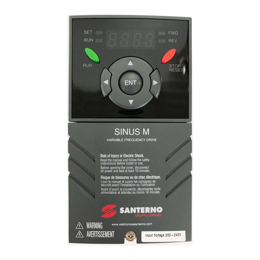
1.2 Product Details Appearance Status LED Display STOP/RESET button RUN button [ENT] button Front cover: Removed when wiring Inverter nameplate Bottom cover: Removed when wiring input power and a motor Inside view after front cover is removed Refer to “1.3 front cover removal” for details. 4-Way button for parameter setting NPN, PNP... -
Page 14: Product Assembling & Disassembling
1.3 Product assembling & disassembling To remove the front cover: Lightly press both the indented sides of the cover and pull up. Press these parts lightly and pull the cover up. To change the inverter fan: Press the both sides of bottom cover lightly and pull out . ... - Page 15 Notes:...
-
Page 17: Chapter 2 - Installation
CHAPTER 2 - INSTALLATION 2.1 Installation precautions CAUTION Handle the inverter with care to prevent damage to the plastic components. Do not hold the inverter by the front cover. It may fall off. Install the inverter in a place where it is immune to vibration (5.9 m/s or lower). - Page 18 When two or more inverters are installed or a cooling fan is mounted in a panel, the inverters and fan must be installed in proper positions with extreme care to keep the ambient temperature below the permissible range. Install the inverter using screws or bolts to ensure that the inverter is firmly fastened. ...
-
Page 19: Dimensions
2.2 Dimensions SINUS M 0001 2S/T - SINUS M 0002 2S/T SINUS M 0003 2S/T - SINUS M 0003 4T SINUS M 0001 4T - SINUS M 0002 4T... - Page 20 SINUS M 0005 2S/T - SINUS M 0007 2S/T SINUS M 0011 2S/T - SINUS M 0014 2S/T SINUS M 0005 4T - SINUS M 0007 4T SINUS M 0011 4T - SINUS M 0014 4T Φ...
- Page 21 SINUS M 0025 2S/T - SINUS M 0030 2S/T SINUS M 00017 2S/T - SINUS M 0020 2S/T SINUS M 0025 4T - SINUS M 0030 4T SINUS M 0017 4T - SINUS M 0020 4T Φ Φ...
- Page 22 Inverter [kW]* Φ [kg] [mm] [mm] [mm] [mm] [mm] [mm] [mm] SINUS M 0001 2S/T 65.5 0.76 SINUS M 0002 2S/T 0.75-1.1 65.5 0.77 SINUS M 0003 2S/T 1.5-1.8 95.5 1.12 SINUS M 0005 2S/T 2.2-3 120.5 1.84 SINUS M 0007 2S/T 4-4.5...
-
Page 23: Chapter 3 - Wiring
CHAPTER 3 - WIRING 3.1 Terminal wiring (Control I/Os) Note: Wiring relates to the NPN configuration (see PNP/NPN selection and connector for communication option). Description Multi-function open collector output MO Common 24V output FX: Forward run MF input terminal (factory setting) RX: Reverse run Input signal common BX: Emergency stop... - Page 24 Power Terminal Wiring * Power terminal wiring (0.4 ~ 7.5kW) 3 Phase AC input Power input (Input rated terminal voltage) Resistor DB resistor connecti terminal Motor connecti Motor terminal ※ Single-phase AC supply in models 2S/T must be applied to Ground terminals R, T terminal...
-
Page 25: Power Terminal Block
SINUS M 0030 4T * Strip the sheaths of the wire insulation for 7mm when a ring terminal is not used for power connection. 7.0mm *For Sinus M 0025 and Sinus M 0030, UL-approved Ring or Fork Terminals must be used. - Page 26 CAUTION Apply the rated torque to terminal screws. Loosen screws can cause short circuit and malfunction. Tightening the screws too much can damage the terminals and cause short circuit and malfunction. Use copper wires only with 600V, 75°C ratings for wiring. ...
- Page 27 WARNING Use the Type 3 grounding method (Ground impedance: Below 100Ω) for 2S/T class inverters. Use the Special Type 3 grounding method (Ground impedance: Below 10Ω) for 4T class inverters. Use the dedicated ground terminal to ground the inverter. Do not use the screw in the case ...
-
Page 28: Control Terminal Block
3.3 Control terminal block Wire size[mm Screw Torque Terminal Description Specification Single size [Nm] Stranded wire P1~P8 Multi-function input T/M 1-8 M2.6 Common Terminal M2.6 Power supply for external M2.6 Output voltage: 12V potentiometer Max output current: 10mA Potentiometer:1 ~ 5kΩ Input terminal for Voltage M2.6 Max input voltage:... -
Page 29: Pnp/Npn Selection And Connector For Communication Option
3.4 PNP/NPN selection and connector for communication option 1. When using DC 24V inside inverter [NPN] SW S8 DC 24 V SW S8 (inside inverter) 2. When using external DC 24V [PNP] SW S8 DC 24 V DC24V (inside inverter) -
Page 30: Optional External Relay
3.5 Optional External Relay An optional external relay with a +24Vdc coil may be connected to the Open Collector output as shown below: Caution: Respect the features of terminals MO and MG. Notes:... -
Page 31: Chapter 4 - Basic Configuration
CHAPTER 4 - BASIC CONFIGURATION 4.1 Connection of peripheral devices to the inverter The following devices are required to operate the inverter. Proper peripheral devices must be selected and correct connections made to ensure proper operation. An incorrectly applied or installed inverter may cause a system malfunction or reduction in product life as well as component damage. -
Page 32: Recommended Mccbs And Mcs
MCCB MCCB Model Model Current Current Current Current Sinus M 0001 2S/T Sinus M 0001 4T Sinus M 0002 2S/T Sinus M 0002 4T Sinus M 0003 2S/T Sinus M 0003 4T Sinus M 0005 2S/T Sinus M 0005 4T... -
Page 33: Recommended Fuses And Reactors
4.3 Recommended Fuses and Reactors AC Input Fuse (External Fuse) AC Input Model DC Reactor Reactor Current Voltage Sinus M 0001 2S/T IM0126000 – – Sinus M 0002 2S/T IM0126002 – Sinus M 0003 2S/T IM0126004 – Sinus M 0005 2S/T IM0126044 –... - Page 34 180 160 150 60 150 82 7x14 IM0126164 0.24 180 160 150 60 150 82 7x14 DC Reactors INDUCTANCE DIMENSIONS HOLE WGT LEAKAGE INDUCTANCE RATINGS MODEL IM0140154 32.5 100 7x10 IM0140204 120 7x14 IM0140254 120 7x14 13.5 IM0140274 0.96 contact Elettronica Santerno...
-
Page 35: Chapter 5 - Programming Keypad
CHAPTER 5 - PROGRAMMING KEYPAD 5.1 Keypad features Display SET/RUN LED FWD/REV LED 7 Segment LED RUN STOP/RESET Up/Down Left/Right Enter [ENT] Display Lit during forward run Lit during reverse run Blinks when a fault occurs Lit during Operation Lit during parameter setting 7 segment... -
Page 36: Alpha-Numeric View On The Led Keypad
5.2 Alpha-numeric view on the LED keypad... -
Page 37: Moving To Other Groups
5.3 Moving to other groups There are 4 different parameter groups in Sinus M series as shown below. Drive group FU group 1 FU group 2 I/O group Basic parameters necessary for the inverter to run. Parameters Drive group such as Target frequency, Accel/Decel time settable. - Page 38 How to move to other groups at the 1st code of each group -. The 1 code in Drive group “0.00” will be displayed when AC input power is applied. -. Press the right arrow () key once to go to Function group 1. -.
-
Page 39: How To Change The Codes In A Group
5.4 How to change the codes in a group Code change in Drive group -. In the 1 code in Drive group “0.00”, press the Up () key once. -. The 2 code in Drive group “ACC” is displayed. -. - Page 40 Navigating codes in a group When moving from F1 to F15 in Function group 1 -. In F1, continue pressing the Up () key until F15 is displayed. -. Moving to F15 has been complete. ♣ The same applies to Function group 2 and I/O group. ♣Note: Some codes will be skipped in the middle of increment ()/decrement () for code change.
-
Page 41: Parameter Setting
5.5 Parameter setting Changing parameter values in Drive Group When changing ACC time from 5.0 sec to 16.0 sec Drive group -. In the first code “0.00”, press the Up () key once to go to the second code. -. - Page 42 -. Press the Ent () key. -. 30.05 is entered into memory. ♣ Sinus M display can be extended to 5 digits using left ()/right () keys. ♣ Parameter setting is disabled when pressing other than Enter Key in step 7.
- Page 43 Changing parameter value in Input/Output group When changing the parameter value of F28 from 2 to 5 FU group 1 -. In F0, press the Ent () key once. -. Check the present code number. -. Increase the value to 8 by pressing the Up () key. -.
-
Page 44: Monitoring Of Operation Status
5.6 Monitoring of operation status Output current display Monitoring output current in Drive group Drive group -. In [0.0], continue pressing the Up () or Down () key until [CUr] is displayed. -. Monitoring output current is provided in this parameter. -. - Page 45 Fault display How to monitor a fault condition in the Drive group During Over- Accel current trip Current Frequency STOP Drive group RESET -. This message appears when an Overcurrent fault occurs. -. Press the Enter () key or UP/Down key once. -.
- Page 46 Parameter initialize How to initialize parameters of all four groups in H93 FU group 2 -. In H0, press the Enter () key once. -. Code number of H0 is displayed. -. Increase the value to 3 by pressing the Up () key. -.
-
Page 47: Chapter 6 - Basic Operation
CHAPTER 6 - BASIC OPERATION 6.1 Frequency Setting and Basic Operation Caution: The following instructions are given based on the fact that all parameters are set to factory defaults. Results could be different if parameter values are changed. In this case, initialize parameter values back to factory defaults and follow the instructions below. - Page 48 Frequency Setting via potentiometer & operating via terminals -. Apply AC input power to the inverter. -. When 0.00 appears Press the Up () key four times. -. Frq is displayed. Frequency setting mode is selectable. -. Press the Ent () key once. -.
- Page 49 Frequency setting via potentiometer & operating via the Run key -. Apply AC input power to the inverter. -. When 0.00 is displayed, press the Up () key three times. -. “drv” is displayed. Operating method is selectable. -. Press the Ent () key. -.
- Page 50 Notes:...
-
Page 51: Chapter 7 - Function List
CHAPTER 7 - FUNCTION LIST 7.1 Drive group Adj. Parameter Setting Factory Description during display name range defaults 0.00 [Frequency 0 ~ 400 This parameter sets the frequency that 0.00 command] [Hz] the inverter is commanded to output. During Stop: Frequency Command During Run: Output Frequency During Multi-step operation: Multi-step frequency 0. - Page 52 Adj. Parameter Setting Factory Description during display name range defaults [Motor RPM] Displays the number of Motor RPM. [Inverter DC Displays DC link voltage inside the link voltage] inverter. [User display This parameter displays the item select] selected at H73- [Monitoring item select].
- Page 53 Adj. Parameter Setting Factory Description during display name range defaults Frq3 [Frequency 0 ~ 7 Digital Keypad setting 1 setting Keypad setting 2 method] V1 1: –10 ~ +10 [V] V1 2: 0 ~ +10 [V] Terminal I: 0 ~ 20 [mA] Terminal V1 setting 1 Analog + Terminal I...
-
Page 54: Function Group 1
7.2 Function group 1 Adj. Parameter Min/Max Factory Description during display name range defaults [Jump code] 0 ~ 64 Sets the parameter code number to jump. 0 ~ 2 Fwd and rev run enable [Forward/ Reverse run Forward run disable disable] Reverse run disable [Accel pattern] 0 ~ 1... - Page 55 Adj. Parameter Min/Max Factory Description during display name range defaults [Max 40 ~ 400 This parameter sets the highest 50.00 frequency] [Hz] frequency the inverter can output. It is frequency reference for Accel/Decel (See H70) Caution: Any frequency cannot be set above Max frequency except Base frequency.
- Page 56 Adj. Parameter Min/Max Factory Description during display name range defaults [V/F pattern] 0 ~ 2 {Linear} {Square} {User V/F} [User V/F 0 ~ 400 It is used only when V/F pattern is set to 15.00 frequency 1] [Hz] 2(User V/F). It cannot be set above F21 –...
- Page 57 Adj. Parameter Min/Max Factory Description during display name range defaults [Motor cooling 0 ~ 1 Standard motor having cooling method] fan directly connected to the shaft A motor using a separate motor to power a cooling fan. [Overload 30 ~ 150 This parameter sets the amount of warning level] current to issue an alarm signal to the...
- Page 58 Adj. Parameter Min/Max Factory Description during display name range defaults [Stall 0 ~ 7 This parameter stops accelerating ramp prevention during acceleration, decreases the select] frequency during constant speed and stops decelerating ramp during deceleration. During During During Decel constant run Accel Bit 2 Bit 1...
- Page 59 [Up-down 0~400 In case of choosing F65 as 1 or 2, it 0.00 step [Hz] means increase or decrease of frequency] frequency according to up-down input. [Draw run Inverter does not run as in mode draw mode select] V1(0~10V) input I(0~20mA) input V1(–10~10V) input [Draw rate]...
-
Page 60: Function Group 2
7.3 Function group 2 Min/Max Factory Adj. Parameter name Description display range defaults during run [Jump code] 0~95 Sets the code number to jump. [Fault history 1] Stores information on the types of faults, the frequency, the [Fault history 2] current and the Accel/Decel [Fault history 3] condition at the time of fault. - Page 61 Adj. Parameter Min/Max Factory Description during display name range defaults [Input/output 0 ~ 3 Input phase Output phase phase loss protection protection protection Bit 1 Bit 0 select] [Power On 0 ~ 1 This parameter is activated when drv is set Start select] to 1 or 2 (Run/Stop via Control terminal).
- Page 62 Adj. Parameter Min/Max Factory Description during display name range defaults [Current level 80~200 This parameter limits the amount of during Speed current during speed search. search] The set value is the percentage of the H33- [Motor rated current]. [P gain during 0~9999 It is the Proportional gain used for Speed Speed search]...
- Page 63 Adj. Parameter Min/Max Factory Description during display name range defaults [Load inertia 0 ~ 2 Select one of the following according to rate] motor inertia. Less than 10 times About 10 times More than 10 times [Carrier 1 ~ 15 This parameter affects the audible sound frequency [kHz]...
- Page 64 Adj. Parameter Min/Max Factory Description during display name range defaults [Integral 0.1~32.0 time for PID [sec] controller (I gain)] [Differential 0 ~ 30.0 time for PID [sec] controller (D gain)] [PID control 0 ~ 1 Selects PID control mode mode Normal PID control select]] Process PID control...
- Page 65 Adj. Parameter Min/Max Factory Description durin display name range defaults g run Sleep delay 0~999 (sec) Sleep Mode delay time 60 sec time Sleep 0~400Hz Sleep Frequency 0.0Hz frequency Wake-up 0~50[%] Wake Up level 2[%] level [KEB select] Sets the KEB [KEB action 110~140[%] Sets KEB action start level according to 125.0...
- Page 66 30 ~ 400 50.00 base [Hz] frequency] motor 0 ~ 2 V/F pattern] motor 0 ~ 15 [%] forward torque boost] : Exception: Since Sinus M-0001 2S/T - Sinus M 0001 4T is Natural convection type, this code is hidden. 7-16...
- Page 67 Adj. Parameter Min/Max Factory Description during display name range defaults motor 0 ~ 15 [%] This parameter actives when the reverse selected terminal is ON after I17-I24 is torque boost] set to 12 {2 motor select}. motor 30~150 [%] stall prevention level] motor...
-
Page 68: I/O Group 2
7.4 I/O group 2 Adj. Min/Max Factory Parameter name Description during display range defaults [Jump code] 0 ~ 81 Sets the code number to jump. [Filter time 0 ~ 9999 Adjusts the responsiveness of NV input constant for NV (–10V~0V). input] [NV input Min 0 ~ –10... - Page 69 Adj. Parameter Min/Max Description Factory defaults during display name range display [Multi-function Forward run command input terminal Reverse run command P1 define] [Multi-function Emergency Stop (Est) input terminal Reset when a fault occurs {RST} P2 define] [Multi-function Jog operation command input terminal Multi-Step freq –...
- Page 70 Adj. Min/Max Factory Parameter name Description during display range default [Input terminal status display] [Output terminal BIT1 BIT0 status display] [Filtering time 1 ~ 15 If the value is set higher, the constant for Multi- responsiveness of the Input terminal function Input is getting slower.
- Page 71 Adj. Min/Max Factory Parameter name Description during display range default [Analog output 10~200 Based on 10V. level adjustment] [Frequency 0 ~ 400 Used when I54 or I55 is set to 0-4. 30.00 detection level] [Hz] Cannot be set higher than F21. [Frequency 10.00 detection...
- Page 72 Adj. Min/Max Factory Parameter name Description during display range defaults [Fault relay 0 ~ 7 When When the When the output] setting the trip other H26– than low voltage trip [Number of voltage occurs auto restart trip occurs try] Bit 2 Bit 1 Bit 0 ...
- Page 73 [Wait time after 0.1 ~ This is the time inverter determines loss of frequency whether there is the input frequency command] [sec] command or not. If there is no frequency command input during this time, inverter starts operation via the mode selected at I62.
- Page 74 Adj. Min/Max Factory Parameter name Description during display range defaults [Brake open 0~180 Sets current level to open the brake. 50.0 current] It is set according to H33’s (motor rated current) size [Brake open 0~10 Sets Brake open delay time. 1.00 delay time] [Brake open FX...
-
Page 75: Chapter 8 - Control Block Diagram
CHAPTER 8 - CONTROL BLOCK DIAGRAM... -
Page 76: Frequency And Drive Mode Setting
8.1 Frequency and Drive mode setting... -
Page 77: Accel/Decel Setting And V/F Control
8.2 Accel/Decel setting and V/F control... - Page 78 Notes:...
-
Page 79: Chapter 9 - Basic Functions
CHAPTER 9 - BASIC FUNCTIONS 9.1 Frequency mode Keypad Frequency setting 1 Group Code Parameter Name Setting Range Initial Unit Drive group 0.00 [Frequency Command] 0 ~ 400 0.00 [Frequency mode] 0 ~ 7 Set Frq – [Frequency mode] to 0 {Frequency setting via Keypad 1}. ... - Page 80 Frequency setting via –10 ~ +10[V] input Group Code Parameter Name Setting Range Initial Unit Drive group 0.00 [Frequency Command] 0 ~400 0.00 [Frequency Mode] 0 ~ 8 [Filter time constant for negative I/O group 0 ~ 9999 input V1] [V1 input minimum negative 0 ~ –10 voltage]...
- Page 81 I1 (Filter time constant for NV input): Effective for eliminating noise in the frequency setting circuit. Increase the filter time constant if steady operation cannot be performed due to noise. A larger setting results in slower response (t gets longer). V1 i I2 ~ I5: Setting input range and corresponding frequency to –10V ~ 0V V1 input voltage ...
- Page 82 Frequency setting via 0 ~ 10 [V] input or Terminal Potentiometer Group Code Parameter Name Setting Range Initial Unit Drive group 0.00 [Frequency Command] 0 ~400 0.00 [Frequency Mode] 0 ~ 8 [Filter time constant for V1 I/O group 0 ~ 9999 input] [V1 input Min voltage]...
- Page 83 Frequency setting via –10 ~ +10[V] voltage input + 0 ~ 20[mA] input Group Code Parameter Name Setting Range Initial Unit Drive 0.00 [Frequency Command] 0 ~400 0.00 group [Frequency Mode] 0 ~ 8 Select 5 in Frq code of Drive group. ...
- Page 84 Frequency setting via RS 485 communication Group Code Parameter Name Setting Range Initial Unit Drive [Frequency Command] 0 ~400 0.00 group [Frequency Mode] 0 ~ 8 Select 7 in Frq code of Drive group. Related codes: I59, I60, I61 ...
-
Page 85: Multi-Step Frequency Setting
9.2 Multi-Step Frequency setting Group Code Parameter Name Setting Range Initial Unit Drive group [Frequency Command] 0 ~ 400 0.00 [Frequency Mode] 0 ~ 7 [Multi-Step frequency 1] 0 ~ 400 10.00 [Multi-Step frequency 2] 20.00 [Multi-Step frequency 3] 30.00 [Multi-function input 0 ~ 29 I/O group... -
Page 86: Operating Command Setting Method
9.3 Operating command setting method Operation via keypad RUN key and STOP/RST key (Modality 0) Group Code Parameter Name Setting Range Initial Unit Drive group [Drive mode] 0 ~ 3 [Direction of motor rotation F, r select] Set drv – [Drive mode] to 0. ... - Page 87 Operating command via FX, RX terminal (Modality 2) Group Code Parameter Name Setting Range Initial Unit Drive group [Drive mode] 0 ~ 3 [Multi-function input I/O group 0 ~ 29 terminal P1 define] [Multi-function input 0 ~ 29 terminal P2 define] Set the drv to 2.
- Page 88 Rotating direction selection via –10 ~ +10[V] input of V1 terminal Group Code Parameter Name Setting Range Initial Unit Drive group [Frequency setting] 0 ~ 7 [Drive mode] 0 ~ 3 Set frq to 2. Inverter is operating as the table below regardless of Drive mode setting. ...
- Page 89 Power On Start select Group Code Parameter Name Setting Range Initial Unit Drive group [Drive mode] 1, 2 0 ~ 3 [Power On Start select] Function group 2 0 ~ 1 Set H20 to 1. When AC input power is applied to the inverter with drv set to 1 or 2 {Run via control ...
-
Page 90: Accel/Decel Time And Pattern Setting
Frequency Reset command When H21 is 0 When H21 is 1 9.4 Accel/Decel time and pattern setting Accel/Decel time setting based on Max frequency Group Code Parameter Name Setting Range Initial Unit Drive group [Accel time] 0 ~ 6000 [Decel time] 0 ~ 6000 10.0... - Page 91 More precise time unit can be set corresponding to load characteristics as shown below. In Sinus M, number display is available up to 5. Therefore, if time unit is set to 0.01 sec, Max Accel/Decel time would be 600.00 sec.
- Page 92 Multi-Accel/Decel time setting via Multi-function terminals Group Code Parameter Name Range Initial Unit Drive [Accel time] group 6000 [Decel time] 10.0 6000 0 ~ 29 [Multi-function input terminal P1 define] group [Multi-function input terminal P12 define] [Multi-function input terminal P3 define] [Multi-function input terminal P4 define]...
- Page 93 Accel/Decel pattern setting Group Code Parameter Name Setting range Initial Unit Function [Accel pattern] Linear group 1 [Decel pattern] S-curve [S-Curve Accel/Decel start Function side] group 2 [S-Curve Accel/Decel end side] Accel/Decel pattern is settable at F2 and F3. ...
- Page 94 Note that setting Frequency Ref. for Accel/decel (H70) is set to Max Freq and target freq is set below Max freq. the shape of S-curve may be distorted. Accel/decel ☞Note: If Target Ref Freq Frequency is below Max Frequency, the waveform Target Freq will be shown with the top portion cut out.
-
Page 95: V/F Control
9.5 V/F control Linear V/F pattern operation Group Code Parameter Name Setting Range Initial Unit [Base frequency] Function group 1 30 ~ 400 50.00 [Start frequency] 0.1 ~ 10.0 0.50 [V/F pattern] 0 ~ 2 Function group 2 [Control mode select] 0 ~ 3 Set F30 to 0 {Linear}. - Page 96 User V/F pattern operation Group Code Parameter Name Setting Range Initial Unit Function group 1 [V/F pattern] 0 ~ 2 [User V/F frequency 1] 0 ~ 400 12.50 [User V/F voltage 4] 0 ~ 100 Select F30 to 2 {User V/F}. ...
- Page 97 Manual torque boost Group Code Parameter Name Setting Range Initial Unit Function [Torque Boost select] 0 ~ 1 group 1 0 ~ 15 [Torque boost in forward direction] [Torque boost in reverse direction] Set F27 to 0 {Manual torque boost}. ...
-
Page 98: Stop Method Select
9.6 Stop method select Decel to stop Group Code Parameter Name Setting Range Initial Unit Function group 1 [Stop mode select] 0 ~ 3 Select 0 {Decel to stop} in F4 code. Motor decelerates to 0 Hz and stops during the time set. ... -
Page 99: Frequency Limit
9.7 Frequency limit Frequency limit using Max Frequency and Start Frequency Group Code Parameter Name Setting Range Initial Unit Function [Max frequency] 0 ~ 400 50.00 group 1 [Start frequency] 0.1 ~ 10 0.50 Max Frequency: Frequency highest limit. Any frequency cannot be set above [Max ... - Page 100 Skip frequency Group Code Parameter Name Setting Range Initial Unit Function [Skip frequency select] 0 ~ 1 group 2 [Skip frequency low limit 1] - 0.1 ~ 400 10.00 [Skip frequency low limit 3] - 0.1 ~ 400 35.00 Set H10 to 1.
-
Page 101: Chapter 10 - Advanced Functions
CHAPTER 10 - ADVANCED FUNCTIONS 10.1 DC brake DC brake at stop Group Display Parameter Name Setting Range Default Unit Function [Stop mode select] 0 ~ 2 group 1 [DC Brake start frequency] 0.1 ~ 60 5.00 [DC Brake wait time] 0 ~ 60 [DC Brake current] 0 ~ 200... - Page 102 DC brake at start Group Display Parameter Name Setting Range Default Unit Function [DC Brake start current] 0 ~ 200 group 1 [DC Brake start time] 0 ~ 60 F12: It sets the level as a percent of H33 – [Motor rated current]. ...
-
Page 103: Jog Operation
10.2 Jog operation Group Display Parameter Name Setting Range Default Unit Function [Jog frequency] 0 ~ 400 10.00 group 1 [Multi-function input 0 ~ 29 group terminal P5 define] Set the desired jog frequency in F20. Select a terminal from P1 - P8 to use for this setting. ... - Page 104 Terminal JOG FX/RX operation Group Display Parameter Name Setting Range Default Unit Function [Jog frequency] 0 ~ 400 10.00 group 1 [Multi-function input 0 ~ 29 terminal P7 define] group [Multi-function input 0 ~ 29 terminal P8 define] Set the desired jog frequency in F20. ...
-
Page 105: Up-Down
10.3 UP-DOWN Up-down storage function Group Display Parameter Name Setting Range Default Unit Drive [Frequency setting method] group [Multi-function input terminal P1 define] [Multi-function input terminal P6 define] 0 ~ 29 group [Multi-function input terminal P7 define] [Multi-function input terminal P8 define] [Up-down frequency Save select]... - Page 106 Up-down mode select Group Display Parameter Name Setting Range Default Unit Drive [Frequency setting method] group [Multi-function input terminal P1 define] [Multi-function input 0 ~ 29 group terminal P7 define] [Multi-function input terminal P8 define] [Up-down mode select] Function group 1 [Up-down step frequency] 0~400...
- Page 107 When F65 is 1: It is increased as much as the step frequency set as F66 at the rising edge of multi- function input set as UP and when up-down is defined, it saves frequency at the falling edge. It is decreased as much as the step frequency set as F66 at the falling edge of rising edge of multi-function input set as DOWN and when up-down is defined, it saves frequency as the falling edge.
-
Page 108: 3-Wire Operation (Start - Stop Via Push Buttons)
10.4 3-Wire operation (Start – Stop via push buttons) Group Display Parameter Name Setting Range Default Unit [Multi-function Input terminal 0 ~ 29 group P1 select] [Multi-function Input terminal P8 select] Select a terminal from P1-P8 for use as 3-Wire operation. ... -
Page 109: Dwell Operation
10.5 Dwell operation Group Display Parameter Name Setting Range Default Unit Function [Dwell frequency] 0.1 ~ 400 5.00 group 2 [Dwell time] 0 ~ 10 In this setting, motor begins to accelerate after dwell operation is executed for dwell time ... -
Page 110: Slip Compensation
10.6 Slip compensation Group Display Parameter Name Setting Range Default Unit Function [Motor type select] 0.2 ~ 7.5 group 2 [Number of motor poles] 2 ~ 12 [Rated slip frequency] 0 ~ 10 2.33 [Motor rated current] 0.5 ~ 50 26.3 [Motor No Load Current] 0.1 ~ 20... - Page 111 H33: Enter the motor nameplate rated current. H34: Enter the measured current when the motor is running at rated frequency without load. Enter 50% of the rated motor current when it is difficult to measure the motor no load current. H36: Enter motor efficiency as shown on the nameplate.
-
Page 112: Pid Control
10.7 PID control Group Display Parameter Name Setting Range Default Unit Function [PID Operation select] 0 ~ 1 group 2 [PID Feedback select] 0 ~ 1 [Proportional gain 0 ~ 999.9 300.0 control] [Integral time for PID control] 0.1~ 32.0 [Derivative time for PID control ] - 0.0~30.0 [PID control mode select]... - Page 113 (i.e. if the error is constant this function does not operate) The error is detected by 0.01 sec in Sinus M. If differential time is set to 0.01 sec and the percentage variation of error per 1 sec is 100%, 1% per 10msec is output.
- Page 114 Normal PID block diagram (H54=0) 10-14...
- Page 115 Process PID block diagram (H54=1) 10-15...
- Page 116 10.7.1 PID reference Adj. Parameter Setting Factory Description during display name Range defaults PID control Selects whether using PID control or not select - User can select the PID control mode in H49. For PID control, the setting value should be set to “1”.
- Page 117 Adj. Parameter Setting Factory Description During display name Range defaults Keypad setting 1 Digital Keypad setting 2 V1 1: –10 ~ +10 [V] V1 2: 0 ~ +10 [V] Frequency Terminal I: 0 ~ 20 [mA] setting 0 ~ 7 Analog Terminal V1 setting 1+ method...
- Page 118 10.7.2 PID feedback PID feedback source is selected in H50 code. PID feedback means a kind of physical value like pressure, so it should be one of analog inputs. For PID feedback, several codes are used. Analog gain, bias, filters are first. Scaling for real value display is second.
- Page 119 2V and internal maximum % is 40/50 X 100 = 80% when input is higher than 8V. : Only for display, Sinus M adopts one more scaling factor by internal %. I83 code is used for minimum display scaling factor and I84 is for maximum. With same condition above, I83 value is 1.0 and I84 value is 20.0.
- Page 120 PID low limit is the additional function code of Sinus M. H55 and H56 are related to each low limit and high limit. When the drive runs, the output frequency should be reached to low limit even if the feedback is higher than the reference. So, except during acceleration time from 0Hz to low limit, the output frequency is between low limit and high limit at any time.
- Page 121 Feedback >45%, then Inverter restarts automatically, and Wake-up should be valid for Sleep mode only. When the drive is in sleep mode, the Sinus M never runs again automatically by wake-up operation after “STOP” command. In this case, the Sinus M operates after the Run command again.
- Page 122 10.7.6 Open Loop1 (Addtional) Adj. Min/Max Factory Parameter Description During display range defaults Multi-function Forward run command (FX) input Reverse run command (RX) terminal P1 define Multi-function Emergency Stop Trip input Reset when a fault occurs terminal P2 define Multi-function Jog operation command input Multi-step freq- Low...
- Page 123 RS485 Multi-functional digital input terminal that is defined to Open Loop1 (28) is activated during “RUN”, the Sinus M should operate with the frequency in FRQ3 of V/F control regardless of the frequency in H40. In case the value set in H40 already belongs to V/F control, only the frequency setting method should be changed.
- Page 124 10.0 Accel/Decel time 0. The output frequency is less than this set value; the Sinus M changes the speed based on the 1st Acc/Dec time values. If higher than this value, it takes the Acc/Dec time in Drv Group. If even one of the Multifunctional digital input is set to XCEL,M,H, then this function should be invalid.
-
Page 125: Auto-Tuning
10.8 Auto-tuning Group Display Parameter Name Setting Range Default Unit Function 0 ~ 1 [Auto tuning] group 2 [Stator resistance (Rs)] 0 ~ 14 Ω [Leakage inductance 0 ~ 300.00 (Lσ)] Setting H41 as 1, the inverter measures the motor parameter. ... -
Page 126: Sensorless Vector Control
10.9 Sensorless Vector Control Group Display Parameter Name Setting Range Default Unit Function [Control mode select] 0 ~ 3 group 2 [Motor type select] 0.2 ~ 7.5 [Rated 0 ~ 10 slip frequency] [Motor rated current] 0.5 ~ 50 [Motor No Load Current] 0.1 ~ 20 [Stator resistance (Rs)] 0 ~ 14... -
Page 127: Energy-Saving Operation
Factory default by motor ratings No-load Rated slip Leakage Stator Input Motor rating Current current [A] freq inductance voltage [kW] rating [A] resistance [Ω] [Hz] [mH] 2.33 14.0 122.00 3.00 6.70 61.00 0.75 2.33 2.46 28.14 2.33 1.13 14.75 2.00 0.869 11.31... -
Page 128: Speed Search
10.11 Speed search Group Display Parameter Name Setting Range Default Unit Function [Speed search select] 0 ~ 15 group 2 [Current level] 80 ~ 200 [Speed search P gain] 0 ~ 9999 [Speed search I gain] [Multi-function output I/O group terminal select] 0 ~ 18 [Multi-function relay select]... - Page 129 (LV) trip is reached. Speed search operation is suitable for loads with high inertia. Sinus M keeps normal operation when instant power failure occurs and power is restored in 15msec. 10-29...
-
Page 130: Auto Restart Try
10.12 Auto restart try Group Display Parameter Name Setting Range Default Unit Function [Number of Auto Restart try] 0 ~ 10 group 2 [Auto Restart time] 0 ~ 60 This parameter sets the number of times auto restart is activated in H26. ... -
Page 131: Operating Sound Select (Carrier Frequency Change)
10.13 Operating sound select (Carrier frequency change) Group Display Parameter Name Setting Range Default Unit Function [Carrier frequency] 1 ~ 15 group 2 This parameter affects the sound of the inverter during operation. When setting carrier frequency Motor sound reduced high Inverter heat loss increased Inverter noise increased... - Page 132 H81-H90 parameters to drive the 2 motor. Define the 2nd motor select when a motor is stopped. H81 ~ H90 parameters function the same as 1 motor. IM 1 iG5+ SINUS M IM 2 10-32...
-
Page 133: Self-Diagnostics Function
10.15 Self-Diagnostics function How to use Self-Diagnostics function Group Display Parameter Name Setting Range Default Unit Function Self-Diagnostic Selection - 0 ~ 3 group 2 Multi-function input 0 ~ 29 I/O group terminal P1 selection Multi-function input terminal P8 selection Select Self-Diagnostic function in H60, Function group 2. - Page 134 Down() key shows When the fault occurs while this function is being performed, press Stop/Reset key or turn the RESET-defined terminal ON to reset the fault. The following table shows the fault type while this function is active. No. Display Fault type Diagnosis UPHF...
-
Page 135: Frequency Setting And
10.16 Frequency setting and 2 drive method select Group Display Parameter Name Setting Range Default Unit Drive mode 1 0 ~ 3 Drive Frequency mode 1 0 ~ 8 group drv2 Drive mode 2 0 ~ 3 Frq2 Frequency mode 2 0 ~ 7 0 ~ 29 Multi-function input... - Page 136 Communication FX P8 : 2nd Change Output Freq. 30.00 ① Accelerate for accel time up to setting frequency by Drive 1 mode, FX signal. ② Drive continuously under FX is ON because DRV2 is 1 when P8 terminal input is ON and change into 2 ③...
-
Page 137: Over Voltage Trip Prevention Deceleration And Power Braking
10.17 Over voltage trip prevention deceleration and Power Braking Group Display Parameter Name Setting Range Default Unit Function Select stop method 0 ~ 3 group 1 BIT 0: Stall prevention under Accel BIT 1: Stall prevention 0 ~ 7 under constant speed BIT 2: Stall prevention under Decel Select voltage limit under... -
Page 138: External Brake Control
10.18 External brake control Group Code Name Set nr. Limit Default Unit Function Controlling method select Group 2 In/Output Brake open current 0~180.0 50.0 Group Brake open delay time 0~10.00 1.00 Sec. Brake open CW Freq. 0~400 1.00 Brake open CCW Freq. 0~400 1.00 Brake close delay time... -
Page 139: Kinetic Energy Buffering
I 84,I 85 I 87 Output Freq. I 82 Output Current I 83 I 86 Motor Speed Brake Output Terminal Drive Command Brake Open Interval Brake Close Interval Brake Close Interval In Case of V/F Constant Control on Control Mode Select CAUTION External Brake control is only used in V/F steady control, and the brake open frequency has to be set smaller than the brake close frequency. -
Page 140: Draw Control
10.20 DRAW Control Group Display Parameter Name Setting Range Default Unit Function DRAW mode select 0 ~ 3 Group 1 DRAW rate 0.0 ~ 100.0 Draw control is a sort of Open Loop tension control. Draw is the ratio of speed difference ... - Page 141 Select 1 and 2 for F70 The center value of analogue input (selected by the set value of I6~I15) as standard, if the input is big it gets (+), if small (-) and gets reflected in the output frequency as the ratio set in F71.
-
Page 142: Phase Pwm
10.21 2 Phase PWM Group Display Parameter Name Setting Range Default Unit Function Group PWM controlling mode 0 ~ 1 0: NORMAL PWM 1: 2 phase PWM Heat loss and leakage current from inverter can be reduced when H48 is set to 1(2 phase PWM) ... -
Page 143: Operating Mode Selection When Cooling Fan Trip Occurs
10.23 Operating mode selection when cooling fan trip occurs Group Display Parameter Name Setting Range Default Unit [Operating mode when Function 0 ~ 1 cooling fan trip occurs] group 2 [Multi-function output I/O group 0 ~ 18 terminal select] [Multi-function relay select] 0 ~ 18 Select 0 or 1 in H78 code. -
Page 144: Parameter Read/Write
10.24 Parameter read/write Group Display Parameter Name Setting Range Default Unit 0 ~ 1 [Parameter read] Function group 2 0 ~ 1 [Parameter write] Used to read/write Inverter Parameters using remote keypad. Caution: Take caution when Parameter write (H92) is executed. By doing this, operation inverter parameters are cleared and the parameters of remote the remote keypad are copied into the inverter. -
Page 145: Parameters Restore Default / Lock
10.25 Parameters Restore default / Lock Parameters restore Group Display Parameter Name Range Default Function [Parameter initialize] group 2 4 groups initialize Drive group initialize F1 group initialize F2 group initialize I/O group initialize Select the group to be initialized and perform it in H93 code. ... - Page 146 Follow the table below to change the password. (Current PW: 123 → New PW: 456) Step Note Keypad display Move to H94 code. Press Enter () key. Enter any number (e.g.: 122). Press the Enter () key. 0 is displayed because wrong value was entered.
- Page 147 See the table below to unlock the user-set parameter via password. Step Note Keypad display Move to H95 code. Press Enter () key. Parameter value cannot be changed in L(Lock) status. Press Enter () key. Enter the password created in H94 (e.g.: 123). Press Enter () key.
-
Page 148: Functions Related To "Fire Mode
Low Voltage (Lut) Ground Trip (GFt) F. The Sinus M cannot operate when the alarms below have tripped, that damage the inverter. Self Diagnosis IGBT Broken (FLtL) Hardware Failure (HWt) Communication Error with I/O board (Err) ... - Page 149 Caution: Once the Sinus M enters the Fire mode, no alarm previously tripped may be reset. To deactivate the Fire mode, turn off and on the inverter AND disable the Fire Mode input. Failure to do so will prevent the alarms tripped from being displayed when the Sinus M is normally operating.
- Page 150 Notes: 10-50...
-
Page 151: Chapter 11 - Monitoring
CHAPTER 11 - MONITORING 11.1 Operating status monitoring Output current Group Display Parameter Name Setting Range Default Unit Drive group CUr [Output current] Inverter output current can be monitored in Cur. Motor RPM Group Display Parameter Name Setting Range Default... - Page 152 User display select Group Display Parameter Name Setting Range Default Unit Drive group vOL [User display select] Function [Monitoring item select] 0 ~ 2 group 2 The selected item in H73- [Monitoring item select] can be monitored in vOL- [User display ...
- Page 153 Power on display Group Code Parameter Setting range Initial Function [Power on display] Frequency command (0.00) group 2 Accel time (ACC) Decel time (DEC) Drive mode (drv) Frequency mode (Frq) Multi-step frequency 1 (St1) Multi-step frequency 2 (St2) Multi-step frequency 3 (St3) Output current (CUr) Motor rpm (rPM) Inverter DC link voltage (dCL)
-
Page 154: Monitoring The I/O Terminal
11.2 Monitoring the I/O terminal Input terminal status monitoring Group Display Parameter Name Setting Range Default Unit [Input terminals status I/O group display] Current input terminal status (ON/Off) can be monitored in I25. For example: The following is displayed when P1, P3, P4 are ON and P2, P5 are OFF. ... -
Page 155: Monitoring Fault Condition
11.3 Monitoring fault condition Monitoring current fault status Group Display Parameter Name Setting Range Default Unit Drive group [Current Fault Display] Fault occurred during operation is displayed in nOn. Up to 3 kinds of faults can be monitored. ... - Page 156 When the fault condition is reset via the STOP/RST key or multi-function terminal, information displayed in nOn will be moved to H1. Moreover, the previous fault info stored in H1 will be automatically moved to H2. Therefore, the updated fault info, will be stored in the H1. When more than 1 fault occurred at the same time, up to 3 types of faults will be stored in one code.
-
Page 157: Analog Output
11.4 Analog Output Group Display Parameter Name Setting Range Default Unit I/O group [Analog output item select] - 0 ~ 3 [Analog output level 10 ~ 200 adjustment] Output item and the level from the AM terminal are selectable and adjustable. ... -
Page 158: Multi-Function Output Terminal (Mo) And Relay (3Ac)
11.5 Multi-function output terminal (MO) and Relay (3AC) Group Code Parameter Setting range Initial [Multi-function FDT-1 output terminal FDT-2 select] FDT-3 [Multi-function relay select] FDT-4 FDT-5 Overload {OLt} Inverter Overload {IOLt} Motor stall {STALL} Over voltage trip {OV} Low voltage trip {LV} Inverter overheat {OH} Command loss During run... - Page 159 I56: When 17 {Fault output} is selected in I54 and I55, Multi-function output terminal and relay will be activated with the value in I56. 0: FDT-1 Check whether the output frequency matches the user-setting frequency. Active condition: Absolute value (preset frequency - output frequency) ≤ Frequency Detection ...
- Page 160 2: FDT-3 Activated when run frequency meets the following condition. Active condition: Absolute value (FDT level - run frequency) ≤ FDT Bandwidth/2 Group Display Parameter Name Setting Range Default Unit [Detected Frequency I/O group 30.00 level] 0 ~ 400 [Detected Frequency 10.00 Bandwidth]...
- Page 161 4: FDT-5 Activated as B contact contrast to FDT-4. Active condition: Accel time: Run Frequency ≥ FDT Level Decel time: Run Frequency > (FDT Level – FDT Bandwidth/2) Group Display Parameter Name Setting Range Default Unit [Detected Frequency I/O group 30.00 level]...
- Page 162 12: During operation Activated when run command is ON and inverter output voltage is different from Freq. command 13: During stop Activated during stop without output voltage/frequency. Freq. command 14: During constant speed Activated during constant speed operation. ...
- Page 163 11.5.1 A, B Contact selection Adj. Setting Factory Parameter name Description During display range defaults A, B Contact A Contact (Normal open) selection B Contact (Normal Close) This function code is for selecting the Contact type of multifunction transistor Digital output MO. MO contact type is A contact (normally open) when setting value is “0”, and B contact (normally closed) when setting value is “1”.
-
Page 164: Output Terminal Select At Keypad-Inverter Communication Error
11.6 Output terminal select at keypad-inverter communication error Group Display Parameter Name Setting Range Default Unit [Output terminal select I/O group when communication 0 ~ 3 error with keypad] Select relay output or open collector output when keypad-inverter communication fails. ... -
Page 165: Chapter 12 - Protective Functions
CHAPTER 12 - PROTECTIVE FUNCTIONS 12.1 Electronic Thermal Protection Group Code Parameter Range Initial Unit Function [ETH (Electronic thermal) 0 ~ 1 group 1 select] [Electronic thermal level for 1 50 ~ 200 minute] [Electronic thermal level for continuous] [Motor type] 0 ~ 1 Select F50 –... -
Page 166: Overload Warning And Trip
Current [%] ETH trip time [sec] 12.2 Overload Warning and trip Overload warning Group Code Parameter Range Initial Unit [Overload warning level] 30 ~ 150 Function group 1 [Overload warning time] 0 ~ 30 [Multi-function output 0 ~ 18 terminal select] group [Multi-function relay select]... -
Page 167: Stall Prevention
Overload trip Group Code Parameter Range Initial Unit Function [Overload trip select] 0 ~ 1 group 1 [Overload trip level] 30 ~ 200 [Overload trip time] 0 ~ 60 Set F56 to 1. Inverter output is turned off when motor is overloaded. ... - Page 168 For example, set F59 to 3 to make stall prevention active during Acceleration and constant run. When stall prevention is executed during acceleration or deceleration, Accel/Decel time may take longer than the user-setting time. When stall prevention is activated during constant run, t1, t2 are executed in accordance with the value ...
-
Page 169: Input/Output Phase Loss Protection
12.4 Input/Output phase loss protection Group Code Parameter Range Initial Unit Function [Input/Output phase loss 0 ~ 3 group 2 protection select] Set H19 value to 1 Output phase loss: Inverter output is shut off at the event of one or more output phase ... -
Page 170: External Trip Signal
12.5 External trip signal Group Code Parameter Range Initial Unit [Multi-function input terminal P1 0 ~ 29 group define] [Multi-function input terminal P7 define] [Multi-function input terminal P8 define] Select a terminal among P1 and P8 to output external trip signal. ... -
Page 171: Inverter Overload
12.6 Inverter Overload Group Code Parameter Range Initial Unit [Multi-function output terminal select] 0 ~ 18 group [Multi-function relay select] Inverter overload prevention function is activated when the current is above inverter rated current. Multi-function output terminal (MO) or Multi-function relay (3ABC) is used as the alarm signal output ... - Page 172 I62: When no frequency command is given for the time set in I63, set the drive mode as the table below. [Drive mode select Continuous operation with after loss of frequency before command loss frequency command] occurs Free run stop (Coast to stop) Deceleration ramp to stop I54, I55: Multi-function output terminal (MO) or Multi-function relay output (3ABC) is used to output ...
-
Page 173: Db Resistor Enable Duty Setting
12.8 DB Resistor Enable Duty setting Group Code Parameter Range Initial Unit [Enable duty limit] 0 ~ 1 Function group 2 [Enable duty] 0 ~ 30 Set H75 to 1. Set %ED (Enable Duty) in H76. H75: DB resistor ED limit setting ... -
Page 175: Chapter 13 - Rs485 Communication
13.2 Specification 13.2.1 Performance specification Item Specification Communication RS485 method Transmission form Bus method, Multi drop Link System Applicable inverter Sinus M series Converter RS232 converter Connectable drives Max. 31 drives Transmission distance Max. 1,200m (Within 700m Recommend) 13-1... -
Page 176: Installation
13.2.2 Hardware specification Item Specification Installation Use S+, S- terminals on control terminal board Power supply Use Insulated power from the inverter power supply 13.2.3 Communication specification Item Specification Communication 19,200/9,600/4,800/2,400/1,200 bps selectable speed Control procedure Asynchronous communication system Communication Half duplex system system Character system... -
Page 177: Operation
13.3.2 Computer and inverter connection System configuration RS232/485 or USB/485 Converter - The number of drives to be connected is up to 31 drives. - The specification of length of communication line is max. 1200m. To ensure stable communication, is suggested to limit the length below 700m. 13.4 Operation 13.4.1 Operating steps... -
Page 178: Communication Protocol (Modbus-Rtu)
13.5 Communication protocol (MODBUS-RTU) Use Modbus-RTU protocol (Open protocol). Computer or other hosts can be Master and inverters Slaves. Inverter responds to Read/Write command from Master. Supported function code Function code Description 0x03 Read Hold Register 0x04 Read Input Register 0x06 Preset Single Register 0x10... - Page 179 CMD: Capital letter Character ASCII-HEX Command ‘R’ Read ‘W’ Write ‘X’ Request for monitoring ‘Y’ Action for monitoring Data: ASCII-HEX Ex) when data value is 3000: 3000 (dec) → ‘0’ ’B’ ’B’ ’8’h → 30h 42h 42h 38h Error code: ASCII (20h ~ 7Fh) Receive/Send buffer size: Receive= 39 bytes, Send=44 bytes Monitor register buffer: 8 Word SUM: to check the communication error...
- Page 180 2) Request for Write: Number of Drive No Address address to Data read “01”~ “W” “XXXX” “1” ~ “8” = n “XXXX…” “XX” “1F” 1 byte 2 bytes 1 byte 4 bytes 1 byte n * 4 bytes 2 byte 1 byte Total bytes = 12 + n * 4 = Max 44 2.1) Acknowledge response:...
- Page 181 4) Action Request for monitor register: Request for read of address registered by monitor register. Drive No “01” ~ “1F” “Y” “XX” 1 byte 2 bytes 1 byte 2 bytes 1 byte Total bytes = 7 4.1) Acknowledge response: Drive No Data “01”...
-
Page 182: Parameter Code List
13.7 Parameter code list <Common area> <Common area>: Accessible area regardless of inverter models (Note 1) Address Parameter Scale Unit R/W Data value FFFF: 0.4kW 0000: 0.75kW 0001: n.u. 0002: 1.5kW 0003: 2.2kW 0004: 3.7kW 0x0000 Inverter capacity 0005: 4.0kW 0006: 5.5kW 0007: 7.5kW 0008: 11.0kW... - Page 183 Address Parameter Scale Unit R/W Data value BIT 0: Stop BIT 1: Forward running BIT 2: Reverse running BIT 3: Fault (Trip) BIT 4: Accelerating BIT 5: Decelerating BIT 6: Speed arrival BIT 7: DC Braking 0x000D Inverter status BIT 8: Stopping BIT 9: not Used BIT10: Brake Open BIT11: Forward run command...
- Page 184 Address Parameter Scale Unit R/W Data value BIT 0~3: Not Used BIT 4: MO (Multi-Output with OC) 0x0010 Output terminal status BIT 5~6: Not Used BIT 7: 3ABC 0x0011 V1 0~3FF Value corresponding to 0V ~ +10V Value corresponding to 0V ~ –10V input when 0x0012 V2 0~3FF Setting FreqMode to 2...
- Page 185 Adj. Parameter Parameter Address Default Unit during R/W Comm Name DRV GROUP A100 6000.0 A101 10.0 6000.0 A102 A103 A104 ST 1 10.00 400.00 A105 ST 2 20.00 400.00 A106 ST 3 30.00 400.00 A107 A108 1800 A109 6553.5 A10A A10B A10C A10D...
- Page 186 A21F User Volt 1 A220 User Freq 2 25.00 400.00 A221 User Volt 2 A222 User Freq 3 37.50 400.00 A223 User Volt 3 A224 User Freq 4 50.00 400.00 A225 User Volt 4 A226 Volt Perc 100.0 40.0 110.0 A227 Energy save A231...
- Page 187 A314 RST restart A315 Speed Search A316 SS Sup-Curr A317 SS P-gain 9999 A318 SS I-gain 9999 A319 Retry number A31A Retry delay 60.0 A31D Motor select maxMotNum A31E Pole number A31F Rated-Slip 2.00 10.00 A320 Rated-Curr 150.0 A321 Noload-Curr 100.0 A322 Motor Input...
- Page 188 A34A DB mode A34B DB %ED A34C FAN Control A34D FAN Trip A34E S/W Version 10.0 A350 2nd Acc time 6000.0 A351 2nd Dec time 10.0 6000.0 A352 2nd BaseFreq 50.00 3000 400.00 A353 2nd V/F A354 2nd F-boost 15.0 A355 2nd R-boost 15.0...
- Page 189 I/O GROUP A401 VR volt x1 viXmax[0] A402 VR freq y1 400.00 A403 VR volt x2 10.00 viXmin[0] v1max A404 VR freq y2 50.00 400.00 A405 V1 filter 9999 msec A406 V1 volt x1 viXmax[1] A407 V1 freq y1 400.00 A408 V1 volt x2 10.00...
- Page 190 A43A Protocol A43B Inv No. A43C Baud rate A43D Lost command A43E Time out 1200 A43F Delay Time msec A440 Parity Stop A441 Read Addr1 42239 A442 Read Addr2 42239 A443 Read Addr3 42239 A444 Read Addr4 42239 A445 Read Addr5 42239 A446 Read Addr6...
-
Page 191: Troubleshooting
13.8 Troubleshooting Refer to Troubleshooting when RS485 communication error occurs. Check points Corrective measures Is the power provided to the converter? Provide electric power to the converter. Are the connections between converter and Refer to converter manual. computer correct? Is Master not polling? Verify the master is polling the inverter. - Page 192 Notes: 13-18...
-
Page 193: Chapter 14 - Troubleshooting & Maintenance
CHAPTER 14 - TROUBLESHOOTING & MAINTENANCE 14.1 Protective functions WARNING When a fault occurs, the cause must be corrected before the fault can be cleared. If protective function keeps active, it could lead to reduction in product life and damage to the equipment. - Page 194 Fault Display and Information Keypad Protective Descriptions display functions Self-diagnostic Displayed when IGBT damage, output phase short, output phase malfunction ground fault or output phase open occurs. Displayed when user-setting parameters fails to be entered into Parameter save memory. error Displayed when an error occurs in the control circuit of the Inverter...
-
Page 195: Fault Remedy
14.2 Fault remedy Keypad Cause Remedy display Caution: When an overcurrent fault occurs, operation must be started after the cause is Overcurrent removed to avoid damage to IGBT inside the inverter. Accel/Decel time is too short compared Increase the Accel/Decel time. to the GD of the load. - Page 196 Fault remedy Keypad Cause Remedy display Decel time is too short compared to the Increase the Decel time. of the load. Regenerative load is connected at the Use Dynamic Brake Unit. Over voltage inverter output. Check whether line voltage exceeds Line voltage is too high.
- Page 197 OLT : OLT is selected when F56 is set to 1 and activated at 200% of F57[Motor rated current] for 60 sec in F58. This can be programmable. Sinus M is not provided with “Overspeed Protection.” 14-5...
-
Page 198: Precautions For Maintenance And Inspection
Check the voltage between terminal P or P1 and N using a tester before proceeding. Sinus M series inverter has ESD (Electrostatic Discharge) sensitive components. Take protective measures against ESD before touching them for inspection or installation. -
Page 199: Chapter 15 - Specifications
CHAPTER 15 - SPECIFICATIONS Input & output ratings: 200-230V SINUS M ■ ■ ■ 2S/T 0001 0002 0003 0005 0007 0011 0014 0017 0020 0025 0030 BA2K2 [HP] 1-1.5 2-2.5 5.5-6 Max capacity 12.5 Motor power 0.75- 1.5- 4.0- 7.5-... - Page 200 4) Max. frequency setting range is extended to 300Hz when H40 (Control mode select) is set to 3 (Sensorless vector control). 5) Maximum output voltage cannot be higher than the input voltage. It can be programmable below the input voltage. 6) Natural convection.
- Page 201 Control Control method V/F, Sensorless vector control Digital command: 0.01Hz Frequency setting resolution Analog command: 0.06Hz (Max freq.: 60Hz) Digital command: 0.01% of Max output frequency Frequency accuracy Analog command: 0.1% of Max output frequency V/F pattern Linear, Squared, User V/F Overload capacity 150% per 1 min.
-
Page 202: Temperature Derating Information
Protective function Over Voltage, Under Voltage, Over Current, Over Current2, Ground Fault current detection, Inverter Overheat, Motor Overheat, Output Phase Open, Overload Trip Protection, Communication Error, Loss of Speed Command, Hardware Fault, Fan trip, Brake error Alarm Stall prevention, overload Momentary Below 15 msec: Continuous operation (should be within rated input voltage, rated Power... -
Page 203: Inverter Efficiency And Heating Loss
15.2 Inverter Efficiency and Heating Loss Measured conditions: 50Hz; 100% Current Load; Default Carrier Frequency. Note: The inverter efficiency is computed by considering the SMPS power consumption. SINUS M ■ ■ ■ 2S/T 0001 0002 0003 0005 0007 0011... -
Page 205: Chapter 16 - Options
OPTIONS 16.1 Remote option 1) Remote Keypad 2) Remote Cable (2M,3M,5M) Remote Cable Model Number Model number Specification On request INV, REMOTE 2M (Sinus M) ZZ0073100 INV, REMOTE 3M (Sinus M) On request INV, REMOTE 5M (Sinus M) 16-1... - Page 206 Installation 1) Take off the top cover of the I/O board kit and remove the hole cover to connect remote cable on the side. 2) Attach the top cover of the I/O board kit and connect the remote cable as shown below. 3) Connect the other side of the remote cable to the remote keypad as shown below.
- Page 207 CAUTION Without Parameter Read, Parameter Write is not available since the Remote memory is empty when the Remote keypad is first used. Do not use the remote cable other than standard ES’. Otherwise, malfunction may occur due to noise input or voltage drop in the keypad. Check for disconnection of the communication cable and/or poor cable connection if “----“...
-
Page 208: Conduit Kit
16.2 Conduit Kit Installation 1) From SINUS M 0001 to SINUS M 0007. 2) From SINUS M 0011 to SINUS M 0014. 16-4... - Page 209 3) From SINUS M 0017 to SINUS M 0030. Conduit kit Conduit Kit Code Model Inverter Conduit Kit 1 ZZ0073102 SINUS M 0001 – SINUS M 0002 Inverter Conduit Kit 2 ZZ0073104 SINUS M 0003 Inverter Conduit Kit 3 ZZ0073106 SINUS M 0005 –...
-
Page 210: Emc Filters
16.3 EMC Filters EMI / RFI POWER LINE FILTERS THE ES RANGE OF POWER LINE FILTERS FFM (Footprint) AND FV SERIES, HAVE BEEN SPECIFICALLY DESIGNED WITH HIGH FREQUENCY ES INVERTERS. THE USE OF ES FILTERS, WITH THE INSTALLATION ADVICE OVERLEAF HELP ENSURE TROUBLE FREE USE ALONG SIDE SENSITIVE DEVICES AND COMPLIANCE TO CONDUCTED EMISSION AND IMMUNITY STANDARDS EN61800-3. - Page 211 SINUS M series FFM Filters (Footprint) NOM. MAX. SINUS 0001 0.4kW 2S/T 0.5mA AC1710101* AC1810302 175x76.5x40 161x53 200÷480VAC 1.2kg SINUS 0002 27mA 1.1kW 2S/T SINUS 0003 0.5mA AC1710201* AC1810302 1.8kW 176.5x107.5x40 162.5x84 1.3kg 200÷480VAC 2S/T 27mA SINUS 0005 2S/T 0.5mA AC1710202* 176.5x147.5x45...
- Page 212 SINUS M series Standard Filters NOM. MAX. SINUS 0017 11kW 2S/T 0.5mA 13.8 AC1711000* AC1810603 100A 250VAC 420x200x130 408x166 – SINUS 0020 27mA 15kW 2S/T SINUS 0025 18kW 2S/T 0.5mA 13.8 AC1711100* 420x200x130 408x166 – AC1810603 120A 250VAC SINUS 0030...
- Page 213 FFM Filters (Footprint) INVERTER SHIELDED CABLE MOTOR FILTER SHIELDED CABLE INVERTER MOTOR FILTER Standard Filters FFM Filters (Footprint) Standard Filters Output ferrite ring FILTER TYPE AC1810302 2xK618 15 26 22 AC1810402 2xK674 23 37 31 AC1810603 3xK40 41 60 58 16-9...
-
Page 214: Braking Resistors
16.4 Braking resistors 2S/T Class Inverter (200÷230Vac) SINUS M 0001 2S/T 0002 2S/T 0003 2S/T 0005 2S/T 0007 2S/T 0011 2S/T Resistor 200Ω 350W* 100Ω 350W 56Ω 350W 56Ω 350W 50Ω 1100W 15Ω 1100W Code RE2644200 RE2644100 RE2643560 RE2643560 RE3083500 RE3083150 2S/T Class Inverter (200÷230Vac) - Page 215 16.4.1 Dimensions Model 350W - IP55 Overall Dimensions, Resistor 350W – IP55 Model 550W - IP55 2 . 5 m m ø 4 . 8 3 0 0 Overall Dimensions, Resistor 550W – IP55 16-11...
- Page 216 Model 1100W - IP55 80-84 M 0 0 6 1 9 - 0 Overall Dimensions, Resistor 1100W – IP55 Model 2200W IP54 – A (mm) B (mm) L (mm) I (mm) P (mm) 177-182 Overall Dimensions, Resistor 2200W – IP54 16-12...
- Page 217 Model 4000W IP20 – A (mm) B (mm) L (mm) H (mm) P (mm) Overall Dimensions, Resistor 4000W – IP20 16-13...
- Page 218 16.4.2 Braking resistor wiring diagram Wire the braking resistor to terminals B1 and B2 on the inverter as short as possible. Power terminal wiring (0.4 ~ 7.5kW) 3 Phase AC input Power input (Input rated terminal voltage) Resistor DB resistor connecti terminal Motor...
-
Page 219: Chapter 17 - Ec Declaration Of Conformity
CHAPTER 17 - EC Declaration of Conformity 17-1...
Need help?
Do you have a question about the sinus M and is the answer not in the manual?
Questions and answers