Table of Contents
Advertisement
Quick Links
QHx220 Hardware User Guide
Table of Contents
QHx220 System Overview ................................................................................................................... 2
General Application System Block Diagram for QHx220 .......................................................................... 2
Description of QHx220 System Block Diagram....................................................................................... 2
Essential Factors to Integrating the QHx220 Device into Your System ..................................................... 3
Connecting the QHx220 Evaluation Board to a PC for Manual Control ...................................................... 4
MTV Product Application ..................................................................................................................... 5
QHx220 Board Layout ....................................................................................................................... 5
QHx220 Board Schematics (for MTV) ................................................................................................... 6
QHx220 Board Bill of Materials (for MTV).............................................................................................. 7
MTV Optimization Setup (Static Coupling Channel) ................................................................................ 7
MTV Application Setup ....................................................................................................................... 9
GPS Product Application ................................................................................................................... 10
QHx220 Board Layout...................................................................................................................... 10
QHx220 Board Schematics (for GPS) ................................................................................................. 11
QHx220 Board Bill of Materials (for GPS) ............................................................................................ 12
GPS Optimization Setup (Static Coupling Channel)............................................................................... 12
GPS Application Setup ..................................................................................................................... 14
WLAN Product Application ................................................................................................................. 15
QHx220 Board Layout...................................................................................................................... 15
QHx220 Board Schematics (for WLAN) ............................................................................................... 16
QHx220 Board Bill of Materials (for WLAN) ......................................................................................... 17
WLAN Optimization Setup (Static Coupling Channel) ............................................................................ 17
WLAN Application Setup ................................................................................................................... 19
Q:ACTIVE........................................................................................................................................... 19
July 6, 2010
AN1559.0
1
CAUTION: These devices are sensitive to electrostatic discharge; follow proper IC Handling Procedures.
1-888-INTERSIL or 1-888-468-3774
Application Note 1559
|
Intersil (and design) is a registered trademark of Intersil Americas Inc.
Copyright Intersil Americas Inc. 2010. All Rights Reserved
All other trademarks mentioned are the property of their respective owners.
Advertisement
Table of Contents

Related Manuals for Intersil QHx220


Summary of Contents for Intersil QHx220
-
Page 1: Table Of Contents
Description of QHx220 System Block Diagram..................2 Essential Factors to Integrating the QHx220 Device into Your System ............. 3 Connecting the QHx220 Evaluation Board to a PC for Manual Control ............4 MTV Product Application ........................5 QHx220 Board Layout ........................5 QHx220 Board Schematics (for MTV) .................... -
Page 2: Qhx220 System Overview
QHx220 noise canceller. The QHx220 integrates the LNA level of the sampled noise at the input of the QHx220. gain stages in the sampler path as well as the DACs... -
Page 3: Essential Factors To Integrating The Qhx220 Device Into Your System
Application Note 1559 to the victim receiver path. It taps the victim receive be achieved using the QHx220 device. It is often path directly. necessary to try multiple tapping points and tapping methods in order to achieve the best possible... -
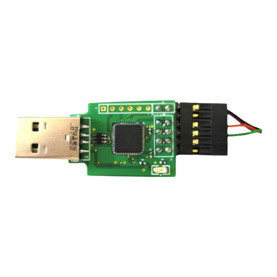
Page 4: Connecting The Qhx220 Evaluation Board To A Pc For Manual Control
SPI bus interface of the a PC for Manual Control QHx220 device. The USB controller board also has a 1.8V The Basic I-Q Control Software User Guide (AN1563) regulated supply that is used to power the QHx220 provides a detailed description of how to install the device. -
Page 5: Mtv Product Application
Application Note 1559 MTV Product Application The following is a general overview on how the QHx220 can be applied for use in Mobile TV product applications. QHx220 Board Layout 1.8V INPUT Rx INPUT (FROM ANTENNA) NOISE SAMPLER INPUT Rx OUTPUT... -
Page 6: Qhx220 Board Schematics (For Mtv)
QHx220 Board Schematics (for MTV) FIGURE 6. SCHEMATIC OF QHx220 EVALUATION BOARD (MTV) -
Page 7: Qhx220 Board Bill Of Materials (For Mtv)
1. Set the desired frequency bandwidth for the range, this range of attenuation should set the aggressor application. power in the middle of the tuning range of the QHx220 2. Change the output power to -45dBm. This provides when using the lowest gain setting of the QHx220. - Page 8 Once the cancellation has been optimized, record the I and Q values for the optimization of the setup used. POWER SPLITTER ATTENUATOR PAD TO SET COUPLING LOSS 50Ω TERMINATION POWER QHx220 SPLITTER CANCELLATION NODE MTV AGGRESSOR PATH PORT 1 PORT 2 NETWORK ANALYZER FIGURE 7.
-
Page 9: Mtv Application Setup
Next, the optimal gain and phase of the QHx220. Therefore, in set the aggressor signal generator to the same channel the MTV application setup, adjust the gain and/or phase... -
Page 10: Gps Product Application
Application Note 1559 GPS Product Application The following is a general overview on how the QHx220 can be applied for use in GPS product applications. QHx220 Board Layout 1.8V INPUT Rx INPUT (FROM ANTENNA) NOISE SAMPLER INPUT Rx OUTPUT (TO RECEIVER) -
Page 11: Qhx220 Board Schematics (For Gps)
GND1 C_Select 10nF 100pF GND1 GND2 L_Select QHx220 100pF C_Select GND1 GND2 ENBAR L_Select GND1 GND1 L_Option GND2 GND1 C_Option JP 2 GND1 GND1 GND1 GND1 GND1 L8, 100nH SP I GND1 FIGURE 11. SCHEMATIC OF QHx220 EVALUATION BOARD (GPS) -
Page 12: Qhx220 Board Bill Of Materials (For Gps)
1. Set the desired frequency bandwidth for the power in the middle of the tuning range of the QHx220 application. when using the lowest gain setting of the QHx220. - Page 13 Once the cancellation has been optimized, record the I and Q values for the optimization of the setup used. POWER SPLITTER ATTENUATOR PAD TO SET COUPLING LOSS 50Ω TERMINATION POWER QHX220 SPLITTER CANCELLATION NODE GPS AGGRESSOR PATH PORT 1 PORT 2 NETWORK ANALYZER FIGURE 12.
-
Page 14: Gps Application Setup
GPS Application Setup level is found that degrades the receive signal strength reported by the GPS receiver, turn on the QHx220 board The following setup should be used for testing QHx220 and set the optimized I and Q values that were noise cancellation ability for a GPS application. -
Page 15: Wlan Product Application
Application Note 1559 WLAN Product Application The following is a general overview on how the QHx220 can be applied for use in WLAN product applications. QHx220 Board Layout 1.8V INPUT Rx INPUT (FROM ANTENNA) NOISE SAMPLER INPUT Rx OUTPUT (TO RECEIVER) -
Page 16: Qhx220 Board Schematics (For Wlan)
C_Select 10nF 100pF GND1 GND2 L_Select QHX2 20 100pF C_Select GND1 GND2 ENBAR L_Select GND1 GND1 L_Option GND2 GND1 C_Option JP 2 GND1 GND1 GND1 GND1 GND1 L8, 100nH SP I GND1 FIGURE 16. SCHEMATIC OF QHx220 EVALUATION BOARD (WLAN) -
Page 17: Qhx220 Board Bill Of Materials (For Wlan)
1. Set the desired frequency bandwidth for the power in the middle of the tuning range of the QHx220 application. when using the lowest gain setting of the QHx220. - Page 18 1. Select the WLAN frequency band of operation. optimized. 2. Start with the lowest gain setting. POWER SPLITTER ATTENUATOR PAD TO SET COUPLING LOSS 50Ω TERMINATION POWER QHX220 SPLITTER CANCELLATION NODE WLAN AGGRESSOR PATH PORT 1 PORT 2 NETWORK ANALYZER FIGURE 17.
-
Page 19: Wlan Application Setup
FIGURE 19. WLAN TESTING SETUP DIAGRAM Intersil Corporation reserves the right to make changes in circuit design, software and/or specifications at any time without notice. Accordingly, the reader is cautioned to verify that the Application Note or Technical Brief is current before proceeding. - Page 20 Mouser Electronics Authorized Distributor Click to View Pricing, Inventory, Delivery & Lifecycle Information: Intersil EBH220BWIMAX-EVALZ...
Need help?
Do you have a question about the QHx220 and is the answer not in the manual?
Questions and answers