Table of Contents
Advertisement
Advertisement
Table of Contents

Related Manuals for Mars GSW1


Summary of Contents for Mars GSW1
- Page 1 GSW1 Simple Universal GSM controller USER MANUAL...
-
Page 2: Table Of Contents
LED INDICATION ..............................7 CONNECTION DIAGRAM ..........................8 GSW1 UNIT MANAGEMENT ..........................9 GSW1 FUNCTIONS WITH PROGRAMMING INSTRUCTIONS ..............10 WEB SERVER - LOG IN ..............................10 WEB SERVER – ADDING UNITS TO USER PROFILE ....................11 WEB SERVER-UNIT MANAGEMENT .......................... 13 CALLER ID ACCESS ............................... - Page 3 Figure 2: WEB Server-Sign In page ....................10 Figure 3: WEB Server-Main page select ADD mode ................ 11 Figure 4: WEB Server-Main page adding GSW1 units ..............12 Figure 5: WEB Server-Unit management window ................13 Figure 6: WEB Server-Caller ID Access ................... 14 Figure 7: WEB Server-Output setting ....................
-
Page 4: For Your Safety
GSW1 USER MANUAL FOR YOUR SAFETY SWITCH ON SAFELY Do not switch the unit on when use of wireless phone is prohibited or when it may cause interference or danger. INTERFERENCE All wireless phones and units may be susceptible to interference, which could affect performance. -
Page 5: Introduction
GSW1 USER MANUAL INTRODUCTION GSW1 is a simple GSM switch system designed to ensure low-cost, simple to install/use, reliable and single box solution for remote managed switching application. It is designed for unlimited range caller ID control. Optional GSW1 supports alarm detection, stay-alive messages, credit detection etc…... -
Page 6: Gsw1 Features And Applications
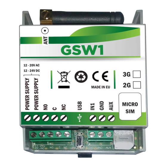
GSW1 USER MANUAL GSW1 FEATURES AND APPLICATIONS Features: Built-in 4 (2G) or 5 (3G) band GSM module Caller ID numbers control (up-to 100 caller ID numbers) 1 output (relay supported) Programming with PC via “USB to Mini USB cable” connected to the unit ... -
Page 7: Start Up
Insert SIM card in GSW1 unit. Connect power cable to GSW1 unit (YOU MUST POWER THE GSW1 UNIT WITH THE POWER SUPPLY IF INCLUDED. Do not power with any other power supply). Power up the unit. -
Page 8: Led Indication
GSW1 USER MANUAL LED INDICATION Green LED (LED1) Indicates the level of the GSM signal from 1 to 5 LED flashes (1 is weak signal, 5 is excellent signal) Yellow LED (LED3) Short flashing indicates that the GSM module is ON, but it is not yet connected on the GSM network. -
Page 9: Connection Diagram
GSW1 USER MANUAL CONNECTION DIAGRAM Before connection the GSW1 please take a look at connection diagram. Figure 1: GSW1: Connection diagram DO NOT USE Power out (12V AUX) for electric lock driving! Use IMPORTANT separate power source for door electric lock! -
Page 10: Gsw1 Unit Management
GSW1 USER MANUAL GSW1 UNIT MANAGEMENT Unit supports different types of management (programming): Unit can be programmed directly by USB connection, with the use of configuration software running on PC (EasySet). Unit can be programmed remotely by using WEB server access. -
Page 11: Gsw1 Functions With Programming Instructions
GSW1 FUNCTIONS WITH PROGRAMMING INSTRUCTIONS As mentioned in previous chapters GSW1 unit can be programmed in various ways, this document will focus on most common programming way: WEB programming. SIM card in the GSW1 unit MUST have DATA PLAN to be able to use... -
Page 12: Web Server - Adding Units To User Profile
After login the user will be diverted to WEB server main window. This page is used to add/remove/search for GSW1 units from the user’s profile. Select “+” sign to select ADD GSW1 units to user’s profile. Figure 3: WEB Server-Main page select ADD mode... -
Page 13: Figure 4: Web Server-Main Page Adding Gsw1 Units
The IMEI is located on the cellular chip and also should be on the card board box of the GSW1. Phone Number: The telephone number of the SIM card in the GSW1 unit - mandatory data. GPRS settings: Information needed to enable data connection between the server and the unit. -
Page 14: Web Server-Unit Management
USER MANUAL 8.3 WEB SERVER-UNIT MANAGEMENT After the GSW1 unit is added to user database, the user can change the configuration of the specific unit. All changes made by the user are listed in the Change Log window. By clicking Send to device button ALL changes are send to the unit. -
Page 15: Caller Id Access
Caller ID access is a very simple way to control relay output defined in Caller ID output setting. User will by calling in the GSW1 unit trigger defined output. Settings for this function are found in the Caller id # tab. -
Page 16: Outputs Settings
GSW1 USER MANUAL 8.5 OUTPUTS SETTINGS The behavior on the outputs is defined in the Output tab. Figure 7: WEB Server-Output setting Output 1 - Settings for output 1: Output (relay) mode: User can select between 3 options Disable-Output is disabled. - Page 17 GSW1 USER MANUAL Additional output settings - Setting are used to link onboard actions with the outputs if needed: Unauthorized call or SMS received: If unauthorized call or SMS is received on the unit this event will activate output defined under this section.
-
Page 18: Administration
GSW1 USER MANUAL 8.6 ADMINISTRATION Administration tab allows user to enable advanced settings: notification of unauthorized access, periodic test messages, lock down of the unit… Figure 8: WEB Server-Notification numbers Phone number, User name: Phone number and user name of the user that will be receiving notification messages. - Page 19 SMS tick the check box in corresponding position. Administration allowed to remote program by SMS: By selection this option the user can “Lock down” the GSW1 unit, preventing any unauthorized user to change any configuration on the unit.
-
Page 20: Miscellaneous
GSW1 USER MANUAL 8.7 MISCELLANEOUS This tab is split into 2 sections. Figure 10: WEB Server-Misc General settings can be found: SMS text Language: define the language of the SMS information send out. User can select appropriate language in drop-down menu. -
Page 21: Contacts
GSW1 USER MANUAL CONTACTS MARS COMMERCE d.o.o. MIRKA VADNOVA 19 4000 KRANJ SLOVENIA TEL: 00 386 4 280 74 00 E-MAIL: info@mars-commerce.com WEB SITE: www.mars-commerce.com TEHNICAL SUPPORT Tomaz HRIBAR Email: tomaz@mars-commerce.com SALES Uros STARE Email: sales@mars-commerce.com Page 20...
Need help?
Do you have a question about the GSW1 and is the answer not in the manual?
Questions and answers