
Subscribe to Our Youtube Channel
Related Manuals for Mars Comfort-Aire Century SV Series


Summary of Contents for Mars Comfort-Aire Century SV Series
- Page 1 Wired Controller Programmable User Manual - VMHxxSV WIRED CONTROLLER PROGRAMMABLE USER MANUAL Model 1731710001195 High Wall SV Series 517.787.2100 • www.marsdelivers.com...
- Page 2 Wired Controller Programmable User Manual - VMHxxSV ● This manual gives detailed description of the precautions that should be brought to your attention during operation. ● In order to ensure correct service of the wired controller please read this manual carefully before using the unit. ●...
-
Page 3: Table Of Contents
Wired Controller Programmable User Manual - VMHxxSV CONTENTS 1. SAFETY PRECAUTIONS................. 1 2. INSTALLATION ACCESSORY..............2 3. INSTALLATION METHOD.................4 4. SPECIFICATION..................10 5. FEATURE AND FUNCTION OF THE WIRED CONTROLLER....11 6. NAME ON THE LCD OF THE WIRE CONTROLLER......12 7. -
Page 4: Safety Precautions
Wired Controller Programmable User Manual - VMHxxSV 1. SAFETY PRECAUTIONS Read the safety precautions carefully before installing the unit. Stated below are important safety issues that must be obeyed. Means improper handling may lead to personal death or severe injury. WARNING Means improper handling may lead to personal injury or property loss. -
Page 5: Installation Accessory
Wired Controller Programmable User Manual - VMHxxSV 2. INSTALLATION ACCESSORY Select the installation location Preparation before installation 1. Please confirm that all the following parts have been supplied. Name Qty. Remarks Wire controller Installation and owner’s manual M4X20 Screws (For Mounting on the Wall) Wall plugs For Mounting on the Wall M4X25... - Page 6 Wired Controller Programmable User Manual - VMHxxSV 2. INSTALLATION ACCESSORY Precaution of install the wire controller 1. This manual provides the installation method of wire controller. Please refer to the wiring diagram of this installation manual to wire the wire controller with indoor unit. 2.
-
Page 7: Installation Method
Wired Controller Programmable User Manual - VMHxxSV 3. INSTALLATION METHOD 1.Wired remote controller structure size figure 4.72" 3/4" 1.81" Fig 3-1 2.44" 2.Wiring Principle Sketch: Insert of the mainboard CN40 ----------------------------------- black ----------------------------------- black yellow yellow ----------------------------------- brown brown ----------------------------------- 4-Core Shield Cable, the length Wire controller Indoor unit mainboard... - Page 8 Wired Controller Programmable User Manual - VMHxxSV 3. INSTALLATION METHOD 3.Wiring figure The connective wires group Mainboard 4-core shielding wire CN40 Fig 3-3 Connect the female joint of wires group from the mainboard with the male joint of connective wires group. (See Fig.3-3) Please connect the other side of connective wires group with the male joint of wires group leads from wire controller.
- Page 9 Wired Controller Programmable User Manual - VMHxxSV 3. INSTALLATION METHOD 4. Fasten the back plate of the wire controller For exposed mounting, fasten the back plate on the wall with the 3 screws (M4×20) and plugs. (Fig.3-5) Back plate Screws (M4×20) Fig 3-5 For flush-mounting, fasten the back plate on the switch box with 2 screws (M4×25) and fasten it on the wall with 1 screw (M4×20).
- Page 10 Wired Controller Programmable User Manual - VMHxxSV 3. INSTALLATION METHOD 5. Battery installation Fig 3-7 Put the battery into the installation site and make sure the positive side of the battery is in accordance with the positive side of installation site.(See Fig.3-7) Please set the time on the first time set-up.
- Page 11 Wired Controller Programmable User Manual - VMHxxSV 3. INSTALLATION METHOD 6. Wiring Top side A. For wiring in the slot, four outletting positions. wire outlet Line groove There are three need cutting. Right side Left side wire outlet wire outlet Line groove Line groove Cutting place of right...
- Page 12 3. INSTALLATION METHOD Wired Controller Programmable User Manual - VMHxxSV 7.Reattach the upper part of the wire controller After adjusting the upper case and then buckle the upper case; avoid clamping the wiring during installation. (Fig 3-11) Fig 3-11 All the pictures in this manual are for explanation purpose only. Your wire controller may be slightly different .The actual shape shall prevail.
-
Page 13: Specification
Wired Controller Programmable User Manual - VMHxxSV 4. SPECIFICATION DC 5V/DC 12V Input voltage Ambient temperature -5~43℃(23~110℉) RH40%~RH90% Ambient humidity... -
Page 14: Feature And Function Of The Wired Controller
Wired Controller Programmable User Manual - VMHxxSV 5. FEATURE AND FUNCTION OF THE WIRED CONTROLLER Feature: LCD display. Malfunction code display: it can display the error code, helpful for service. 4-way wire layout design, no raised part at backside, more convenient to place the wires and install the device. -
Page 15: Name On The Lcd Of The Wire Controller
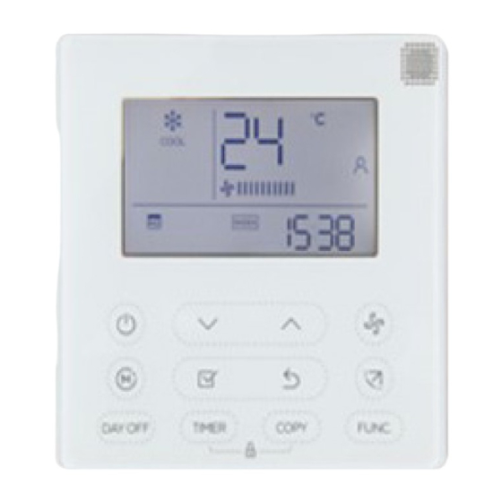
Wired Controller Programmable User Manual - VMHxxSV 6. LCD OF THE WIRE CONTROLLER 1 Operation mode indication 8 PTC function indication 2 Fan speed indication 9 C° / F° indication 3 Left-right swing indication 10 Temperature display 4 Up-down swing indication 11 Lock indication 5 Faceplate function indication 12 Room temperature indication... -
Page 16: Name Of Button On The Wire Controller
Wired Controller Programmable User Manual - VMHxxSV 7. BUTTONS ON THE WIRE CONTROLLER swing swing... - Page 17 Wired Controller Programmable User Manual - VMHxxSV 7. BUTTONS ON THE WIRE CONTROLLER 1 Power Button 2 Mode(A/B) Button 3 Adjust Button 4 Fan speed Button 5 Up-down Airflow Direction and Swing Button 6 Left-right Airflow Swing Button 7 Follow me(PTC) Button 8 Timer Button 9 Day off(Del) Button 10 Confirm Button...
-
Page 18: Preparatory Operation
Wired Controller Programmable User Manual - VMHxxSV 8. PREPARATORY OPERATION Set the current day and time Press the Timer button for 3 seconds or more. The timer display will flash. Press the button “ + ” or “ - ” to set the date. The selected date will flash. -
Page 19: Operation
Wired Controller Programmable User Manual - VMHxxSV 9. OPERATION Remote signal receiving function The wired remote controller can be a remote signal receiving device, you can use the wireless remote controller to control the air-conditioner through the wired remote controller when the system has been powered on. To start/stop operation Press the Power button. - Page 20 Wired Controller Programmable User Manual - VMHxxSV 9. OPERATION Fan speed setting Press the Fan speed button to set the fan speed. (This button is unavailable when in the mode of Auto or Dry) Room temperature sensor selection Indoor Unit Press the Follow me/PTC button to select whether the room temperature is detected at the indoor unit or the wire controller.
- Page 21 Wired Controller Programmable User Manual - VMHxxSV 9. OPERATION PTC function (on some models) Press the Follow me/PTC button for 2 seconds or more to activate the PTC function,when the unit is under the Heat mode. Press the buttons again for 2 seconds or more to deactivate the PTC function.
- Page 22 Wired Controller Programmable User Manual - VMHxxSV 9. OPERATION Faceplate function (on some models) 1.When the unit is off,Press the Mode(A/B) button long to activate the faceplate function.The mark will flash. The F2 mark appears when the faceplate is adjusted. 2.
- Page 23 Wired Controller Programmable User Manual - VMHxxSV 9. OPERATION Up-Down airflow direction and swing (on some models) button to adjust the Up-down airflow direction. 1.When pressing the button once and quickly ,the Up-down airflow direction setting feature of the louver is activated. The moving angle of the louver is 6° for each pressing.
-
Page 24: Timer Functions
Wired Controller Programmable User Manual - VMHxxSV 10. TIMER FUNCTIONS WEEKLY timer Use this timer function to set operating times for each day of the week. On timer Use this timer function to start air conditioner operation.The timer operates and air conditioner operation starts after the time has passed. Off timer Use this timer function to stop air conditioner operation.The timer operates and air conditioner operation stops after the time has passed. - Page 25 Wired Controller Programmable User Manual - VMHxxSV 10. TIMER FUNCTIONS To set the On or Off TIMER Press the Timer button to select the No display timer Press the Confirm button and the Clock display is flashing. confirm ex.Off timer set at PM 6:00 Press the button “...
- Page 26 Wired Controller Programmable User Manual - VMHxxSV 10. TIMER FUNCTIONS To set the On and Off TIMER Press the Timer button to select the timer Press the Confirm button and the Clock display is flashing. confirm confirm Press the button “ + ” or “ - ” to set the time of On timer,and then press the Confirm button to confirm the setting.
-
Page 27: Weekly Timer
Wired Controller Programmable User Manual - VMHxxSV 11. WEEKLY TIMER Weekly timer setting timer confirm Press the Timer button to select the and then press the Confirm button to confirm. Day of the week setting confirm Press the button “ + ” and “ - ” to select the day of the week.and then press the CONFIRM button to confirm the setting. - Page 28 Wired Controller Programmable User Manual - VMHxxSV 11. WEEKLY TIMER Up to 8 time scales can be set in one day. Mode,temperature and fan speed in different time scale can be set. ex.Tuesday time scale 1 Time setting Press the button “ + ” and “ - ” to set the time.and then press the Confirm button to confirm the setting.
- Page 29 Wired Controller Programmable User Manual - VMHxxSV 11. WEEKLY TIMER Press the button “ + ” and “ - ” to set the room temperature .and then press the Confirm button to confirm the setting. NOTE:This setting is unavailable when in the mode of Fan or Off. Fan speed setting confirm Press the button “...
- Page 30 Wired Controller Programmable User Manual - VMHxxSV 11. WEEKLY TIMER WEEKLY timer operation ● To start Press the Timer button to select the ,and the the timer starts automatically. ● To cancel Press the Power button to cancel the timer mode. The timer mode can also be canceled by changing the timer mode using the Timer button.
- Page 31 Wired Controller Programmable User Manual - VMHxxSV 11. WEEKLY TIMER Press the Day off button to set the DAY OFF. mark is hidden ex.The DAY OFF is set for Wednesday The DAY OFF can be set for other days by repeating the steps 2 and 3. Press the Back button to back to the weekly timer.
- Page 32 Wired Controller Programmable User Manual - VMHxxSV 11. WEEKLY TIMER Press the Copy button,the letter “CY” will be shown on the LCD. Press the button “ + ” and “ - ” to select the day to copy to. Press the Copy button to confirm . mark flashes quickly ex.
- Page 33 Wired Controller Programmable User Manual - VMHxxSV 11. WEEKLY TIMER Delete the time scale in one day. During the weekly timer, press the Confirm button. Press the button “ + ” and “ - ” to select the day of the week.and then press the Confirm button to confirm the setting.
-
Page 34: Fault Alarm Handing
Wired Controller Programmable User Manual - VMHxxSV 12. FAULT ALARM HANDING D ISPLAY MALFU N C T ION & PROT EC T ION D EFIN E DIGITAL TUBE Error of communication between wire controler and indoor unit The faceplate is abnormal Please check the error display of indoor unit and read <<OWNER'S MANUAL>>... - Page 35 Wired Controller Programmable User Manual - VMHxxSV The design and specifications are subject to change without prior notice for product improvement.Consult with the sales agency or manufacturer for details QS01X-001AEN 16117100A00083 20170412...
- Page 36 Wired Controller Programmable User Manual - VMHxxSV 10/2022...
Need help?
Do you have a question about the Comfort-Aire Century SV Series and is the answer not in the manual?
Questions and answers