Table of Contents
Advertisement
Quick Links
Pixie-20P
™
™
Castle Creations
By
Programmable Sub Micro Digital Motor Control
1.0
Features of the Pixie-20P:
• Microprocessor controlled
• Low Resistance (.0027 ohms)
• High rate (2800 Hz) switching (PWM)
• Up to 20 Amps continuous current (with proper air flow)
• High Output (1.5amp) Battery Eliminator Circuit (BEC)
provides power to receiver and servos - eliminates separate
receiver battery
• Five – seven cells with four micro servos
• Eight cells with three micro servos
• Nine or ten cells with two micro servos
• Eighteen cells MAX with BEC disabled
• Programmable LV cutoff (none, 5.0V*, 6.0V, 7.2V or 8.4V)
• Programmable motor cutoff – hard with reset* or soft
• Programmable throttle range – auto-calibrating* or fixed
end points
• Safe "power on" arming program ensures motor will not
accidentally turn on
• Low torque "soft start" prevents damage to fragile
gearboxes
• Auto shut down when signal is lost or radio interference
becomes severe
• Rugged surface mount construction
* Initial factory settings
2.0
Wiring Your Pixie-20P:
Tools required:
Wire cutters
Wire strippers (optional)
Parts required:
Solder (rosin core "electronic" solder - do not use acid core "plumbers" solder)
Battery connector
2.1
Servo Ratings with BEC Enabled
Servo Type
5-7 cells
Standard (micro) servos
4
High Torque servos
3
2.1
Adding the Battery Connector
The battery connector is attached to the side of the controller with black and red wires. Cut the wires to the
length you require on the battery side. Strip off of the wire insulation to expose just enough wire to attach the
battery connector. (Note: if you do not have a pair of wire strippers, you can use a modeling knife to
carefully cut through the insulation around the wire. Then the insulation should easily pull off the wire.)
Pixie-20P
User Guide
™
This document, Pixie-20P software, and Pixie-20P PCB layout are all Copyright 2002 by Patrick del Castillo and
Soldering Iron (25-40 watts - Do not use a soldering "gun")
8 cells
9-10 cells
3
2
2
Not Recommended
Page 1 of 5
Attach the battery connector to the wires ENSURING THAT THE POLARITY (red wire to battery red wire,
black wire to battery black wire) IS CORRECT, following the instructions for the battery connector.
2.2
Attaching the Motor Leads
The motor is connected to the side of the controller with red and white wires. Cut the wires to the length you
require on the motor side. Strip the wire insulation to expose just enough wire to solder the wires to the motor
terminals. (Note: If you do not have a pair of wire strippers, you can use a modeling knife to carefully cut
through the insulation around the wire. Then the insulation should easily pull off the wire). There should be
a '+' symbol or a RED DOT on the end of your motor which indicates which terminal must be connected to
the RED wire. Connect the other terminal to the white wire. A fuse (5-10 amps) may be connected inline in
either the white or red power wire. A fuse is recommended for the safest operation. DO NOT PLACE A
FUSE IN THE CIRCUIT BETWEEN THE BATTERY AND SPEED CONTROL. YOU COULD
LOSE CONTROL OF THE MODEL.
Align the wires carefully and solder to the motor terminals. Ensure that all connections (battery and motor)
are correctly polarized.
IMPORTANT NOTE: YOU MUST BE SURE THAT ALL CONNECTIONS ARE CORRECT WHEN
CONNECTING THE SPEED CONTROL. Incorrectly connecting the speed control could cause permanent
damage to the controller.
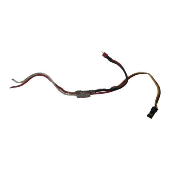
Battery
Connector
Pixie-20P
←Batt Motor→
Fig 1: System power wiring diagram
2.3
Connecting the Receiver
Older AirTronics systems require a minor change to the wiring in the receiver connector supplied with the
speed controller. Reverse the red (power) and brown (ground) wires in the connector plug so that the plug is
orange/brown/red. Use a knife blade to lift the retention tabs on the connector plug to remove the red and
brown wires. Insert the wires back into the plug and press down the retention tab.
Connect the receiver lead (the three color wires with a connector on the end) to the throttle channel on your
receiver (usually channel 3). Do not connect a battery to the receiver, as the Pixie-20P will supply power to
the receiver and servos through the receiver connector. If you are using more than eight cells, you will need
to use a separate receiver battery. See the section 4.0 (under the heading BEC) for instructions on disabling
the BEC to use a separate receiver battery.
ALWAYS PERFORM A RANGE CHECK BEFORE FLYING WITH ANY NEW SPEED
CONTROLLER! PERFORM YOUR RANGE CHECK AT FULL THROTTLE, HALF
THROTTLE AND NO THROTTLE.
Rev 2-dated 09/17/02
Castle Creations™.
All Rights Reserved.
Pixie-20P
Fuse*
Motor
* Suggested 5-10 Amp (if installed)
Advertisement
Table of Contents

Subscribe to Our Youtube Channel
Related Manuals for Castle Creations Pixie-20P


Summary of Contents for Castle Creations Pixie-20P
- Page 1 8 cells 9-10 cells receiver (usually channel 3). Do not connect a battery to the receiver, as the Pixie-20P will supply power to Standard (micro) servos the receiver and servos through the receiver connector. If you are using more than eight cells, you will need...
- Page 2 (pry the retaining tab up, remove the pin, and insulate the pin with It is also possible that the microprocessor on the Pixie-20P is being overwhelmed by noise from the motor. electrical tape.) Then you may safely use a battery with your receiver.
- Page 3 Castle Creations™ Verify Normal Operation Castle Creations™ Email: support@castlecreations.com If this is the first time the Pixie-20P has been used, it is important to verify that the Pixie-20P operates 18773 W 117 Street Fax: (913) 438-1394 normally with your transmitter otherwise programming may not function properly. Follow the instructions in Olathe, KS 66061 http://www.castlecreations.com...
- Page 4 20P has accepted your answer, it will flash the LED rapidly. After the LED starts it’s rapid flashing, move the throttle stick to the middle position to confirm that you are ready for the Pixie-20P to ask the next question.
- Page 5 Recommended for helicopter use Auto Throttle Calibration is a feature of the Pixie-20P that automatically adjusts the throttle range to match the range of the transmitter in use. In most cases, Auto Throttle Calibration is desirable, however, in some cases (such as with a helicopter tail rotor control) a fixed throttle response is desirable.
Need help?
Do you have a question about the Pixie-20P and is the answer not in the manual?
Questions and answers