Motorola PMP 320 User Manual
Network
Hide thumbs
Also See for PMP 320:
- Hardware installation (146 pages) ,
- Configuration manuallines (37 pages) ,
- Administration and configuration manual (95 pages)
Table of Contents
Advertisement
PMP 320 Access Network
User Guide
Issue 2
November 2009
Notices
See important regulatory, legal, and safety notices in section 6 on page 18.
Trademarks, Product Names, and Service Names
MOTOROLA, the stylized M Logo, and all other trademarks indicated as such herein are
registered trademarks of Motorola, Inc. ® Reg. US Pat & Tm. Office. All other product or service
names are the property of their respective owners.
© 2009 Motorola, Inc. All rights reserved
http://motorola.wirelessbroadbandsupport
1
Advertisement
Table of Contents

Related Manuals for Motorola PMP 320


Summary of Contents for Motorola PMP 320
-
Page 1: User Guide
PMP 320 Access Network User Guide Issue 2 November 2009 Notices See important regulatory, legal, and safety notices in section 6 on page 18. Trademarks, Product Names, and Service Names MOTOROLA, the stylized M Logo, and all other trademarks indicated as such herein are registered trademarks of Motorola, Inc. ® Reg. US Pat & Tm. Office. All other product or service names are the property of their respective owners. © 2009 Motorola, Inc. All rights reserved http://motorola.wirelessbroadbandsupport ... -
Page 2: Table Of Contents
Table of Contents Using This User Guide ..................... 4 FINDING THE INFORMATION YOU NEED ............4 Becoming Familiar with This User Guide ............4 Searching This User Guide .................. 5 Finding Parameter and Field Definitions for Module Web Pages ...... 5 NEW PRODUCTS AND FEATURES DESCRIBED IN THIS ISSUE ......5 NEW DESCRIPTIONS AND REVISIONS IN THIS ISSUE........... 5 PORTFOLIO OF WIRELESS BROADBAND SOLUTIONS.......... 5 PRODUCTS COVERED BY THIS USER GUIDE ............6 PRODUCTS NOT COVERED BY THIS USER GUIDE ..........6 1.10 CONVENTIONS ....................6 1.11 TECHNICAL SUPPORT ..................7 1.12 FEEDBACK ON DOCUMENTATION ..............8 Product Description .................... - Page 3 CPE Frequency and Channel bandwidth Configuration........50 Authentication Configuration ................... 52 AP Authentication Parameter Configuration............ 52 AAA Authentication Configuration ..............52 Aradial server installation (Refer to Appendix A for initial steps) ....53 Add a NAS......................54 Add a GROUP ....................56 Add a USER......................58 Verification of AAA configuration ..............61 Setting up CPE for Authentication ..............61 Quality of Service Configuration................63 10.1 Brief overview of the quality of service section ..........63 10.2 QoS profile creation ..................63 10.3 Classification profile creation: ................65 10.4 Service flow creation: ..................
-
Page 4: Using This User Guide
Contents in either the paper or the electronic version of this guide can save much more time in finding information now and in the future. The List of Procedures may be especially useful in the paper version of this guide, particularly where you mark those procedures that you wish to frequently see. In contrast, the List of Figures and List of Tables are most useful for automated searches on key words in the electronic version of this guide. If a match is present, the match is the first instance that the search finds. Quick Reference This user guide comprises six sections, as described in Table 1. Section Purpose Guide to This User Identifies Guide products covered by this user guide. (this section) products covered by their own separate user guides. how this user guide is organized. where to find module web pages and parameter descriptions. what the various typefaces and admonitions indicate. how to contact Motorola. Product Description Provides references to RF and networking theory. overviews and comparisons of products and how they communicate. descriptions of data handling and synchronization. a review of optional features. resources for developing familiarity and proficiencies Planning Provides essential information for evaluating an area for a network. specifying the IP addresses and frequencies to use. Configuration Provides guidance for expanding network coverage. ... -
Page 5: Searching This User Guide
monitoring and changing variables through SNMP. Installation Provides systematic approaches for avoiding hazards from RF and natural causes. testing, storing, and deploying equipment. Reference Provides supplemental information such as Information authorizations, approvals, and notices. a bibliography of adjunctive information sources. a history of changes in documentation. Glossary Defines terms and concepts that are used in this user guide 1.3 Searching This User Guide To search this document and the software release notes of supported releases, look in the Table of Contents for the topic and in the Adobe Reader® search capability for keywords that apply.1 These searches are most effective when you begin the search from the cover page because the first matches may be in titles of sections, figures, tables, or procedures. 1.4 Finding Parameter and Field Definitions for Module Web Pages Because this user guide is sequentially arranged to support tasks, and various tasks require different settings and readings, parameter and field definitions are scattered according to the tasks that they support. 1.5 NEW PRODUCTS AND FEATURES DESCRIBED IN THIS ISSUE This section is a placeholder where other new descriptions, as wells as clarifications and corrections, will be listed in future issues. 1.6 NEW DESCRIPTIONS AND REVISIONS IN THIS ISSUE This section is a placeholder where other new descriptions, as wells as clarifications and corrections, will be listed in future issues. 1.7 PORTFOLIO OF WIRELESS BROADBAND SOLUTIONS The Motorola portfolio of wireless broadband solutions provides a range of flexible, interworkable, products ... -
Page 6: Products Covered By This User Guide
− licensed 802.16e point‐to‐multipoint solutions (PMP 320) − unlicensed point‐to‐multipoint solutions (PMP 100, PMP 400) − point‐to‐point solutions − Enterprise Wireless LAN (WLAN) solutions ‐ Mesh, including the MOTOMESH series of products ‐ Wireless Manager, a network manager capable of managing many of these elements 1.8 PRODUCTS COVERED BY THIS USER GUIDE This user guide describes planning, configuration, installation, and operation of the CAP 320 (the Access Point member of the PMP 320 family) and also includes information to help the operator plan and deploy a PMP 320 access network. 1.9 PRODUCTS NOT COVERED BY THIS USER GUIDE Related PMP 320 Access Network devices have their own user guides: CSM 320, the Cluster Management Module 4 (CMM4), Network Updater Tool (CNUT), and Wireless Manager (WM). 1.10 CONVENTIONS This document employs distinctive fonts to indicate the type of information, as described in Table ... -
Page 7: Technical Support
1.11 TECHNICAL SUPPORT Here is the escalation path for resolution of a problem: 1. Check this user guide 2. Consider checking the Community Forum and Knowledge Base at http://motorola.wirelessbroadbandsupport.com/support/community. 3. Escalate the problem to your supplier or reseller. 4. Escalate the problem to Canopy Technical Support or other designated Tier 3 technical support: technical-support@canopywireless.com U.S. and Canada Email:... -
Page 8: Feedback On Documentation
1‐866‐961‐9288 Latin and Central America Email: technical‐support@canopywireless.com Argentina 0800‐666‐2789 Brazil 0800‐891‐4360 Columbia 01‐800‐912‐0557 Mexico 001‐800‐942‐7721 Peru 0800‐70‐086 All other countries +420 533 336 946 Europe, Middle East, Email: essc@motorola.com and Africa Denmark 043682114 France 0157323434 Germany 06950070204 Italy 0291483230 Lithuania 880 030 828 Netherlands 0202061404 Norway 24159815 Portugal 0217616160 Spain 0912754787 Russia 810 800 228 41044 Saudi Arabia 800 844 5345 South Africa 0800981900 United Kingdom 0203 0277499 Asia Pacific Email: WiBBsupport.apac@motorola.com +6048503854 (9am ‐ 5pm Malaysia Time) +420 533 336 946 (outside hours) When you send e‐mail or call, please include, as appropriate, software release on each module, IP addresses, MAC addresses, and features enabled. 1.12 FEEDBACK ON DOCUMENTATION Is this document accurate, complete, and clear? How can it be improved? Send your feedback on documentation to technical‐documentation@canopywireless.com. Issue ... -
Page 9: Product Description
2 Product Description A PMP 320 Access Network provides a low cost point‐to‐multipoint broadband infrastructure optimized for fixed outdoor applications. The access point is an 802.16e micro base station with WiMAX CPE interoperability. The system offers an integrated, all‐outdoor solution with simple installation for rapid deployment. Target applications for the PMP 320 Access Network include Tier 2/tier 3 carriers, where the PMP 320 system provides a cost‐ effective, reliable broadband connectivity for residential and business customers Government network operators, where the PMP 320 system provides broadband‐based infrastructure for administrative networks Wireless service providers, with broadband network service for any size operation Wireline service providers, with broadband wireless extensions for existing DSL or cable networks. As shown in Figure 1, a PMP 320 network consists of APs – CAP 320 Access Points, usually tower‐mounted in a four‐sector configuration. SMs ‐ CSM 320 Subscriber Modules, Customer Premise Equipment (CPE), usually mounted on a residence or other structure, and powered by a power adapter providing standard 802.3af power over Ethernet. CMM4 (Cluster Management Module 4) – a zero‐footprint enclosure housing a GPS module connected to a GPS antenna, sync‐ and power‐ injection circuitry, surge protection, and a managed switch. The CMM is used to provide custom “sync over power over Ethernet” to the APs as well as offering a networked, managed switch. ... - Page 10 DNS Server NMS (optional) AAA Server DHCP Server (optional) (e.g., Wireless Manager) (optional) (optional) Figure 1: High level network diagram In addition, a PMP 320 network usually also requires a AAA Server – Authentication, Authorization, and Accounting server using the RADIUS (Remote Authentication Dial In User Service) protocol EMS – an Element Management System, such the Motorola One Point Wireless Manager DHCP Server – Dynamic Host Configuration Protocol server DNS Server – Domain Name System server CNUT – Network Update Tool for updating device software Motorola offers PMP 320 equipment that operates in the spectrum ranges as shown in Table 4 Licensed System Name AP Name SM Name AP Model Frequencies...
-
Page 11: Access Point (Ap)
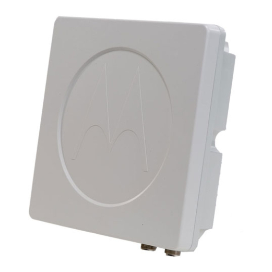
2.1 Access Point (AP) A PMP 320 Access Point (AP) is an 802.16e micro base station that connects wirelessly to up to 200 PMP 320 Subscriber Modules (SMs) or WiMAX CPEs. The AP consists of a connectorized antenna and radio, as shown in Figure 2, with the radio shown separately in Figure 3. The standard antenna is a dual‐ polarity 16.5 dBi antenna typically mounted in a four 90° sector configuration. The AP is manageable by local web interface, as well as SNMP or the Motorola One Point Wireless Manager. ... - Page 12 address from a network DHCP server, or be manually assigned its IP a ddress. The AP can be configured to respond to SM DHCP requests either by relaying the requests to a network DHCP server, or function as a DHCP se rver itself. The AP can be configured ei ther to use an external AAA (Authentication, A uthorization, and Accounting) server, or u se a minimal internal AAA server. When configu red to use an external AAA serve r, the AP serves as a relay between SMs and the AAA server for authenticat ion requests, a nd serves as a RADIUS client communicating with the AAA server for authorization of SM services. The AP has an embedd ed we b serve r for configuring using a web browser. The AP supp orts SN MP v1 and v2c, and uses standard 802.16e MIBs (Management Information Base) as well as the Motorola 802.16e AP MIB. Specification s for the CAP 320 are listed in Table 1. ...
- Page 13 Table 1: CAP 32 0 Specification CAP 20 3 FREQUENCY 3.3 – 3.4 GHz 3.4 – 3.5 G Hz 3.6 – 3.8 GHz (CAP 33320) (CAP 35320) (CAP 36320) PERFORMANCE Physical Layer 802.16e‐2005 (5 MH z channel: 512 FFT; 7/10MHz hannel: 1024FFT) MAC layer 802.16e‐2005 Maximum Up to 2 x 25 dBm; Transmiss ion Local Regulatory Requirement s May Limit Max Power Transmission Power. See table 5 on page 19 for FC limits in U.S. applications. Maximum EIRP Integrated: 2 x 41.5 dBm Connectorized: Antenna Dep endant Local Regulatory Requirement s May Limit Max EIRP. ...
-
Page 14: Subscriber Module (Sm)
118 miles/hr (190 km/hr) Dimensions Integrate d: ~711 x 195 x 240mm (LxWxD) Connectorized: ~330 x 195 x 140mm Weight Integrated: 5.5 kg Connectorized: 2.2 kg INTERFACE Interface /100 Base T, half/full duplex. Rate auto negotiated (802. 3 compliant) Protocols Used IPv4, UDP, TCP, IP, ICMP, SNMP, HTTP, FTP, RIP, DHCP Relay Network Web‐Based Interface; SNMPv2c; or Motorola Wireless nagement Manager CERTIFICATION S FCC ID n/a n/a ABZ89FT7632 Industry Canada n/a 109W‐3530APC 109W‐3630APC Certification Number CE "CE" marked & compliant to EN300 328. DoCs are available at ... -
Page 15: Installing The Ap
2.3 INSTALLING THE AP General communications equipment, infrastructure, and facilities site design should be performed in line with Motorola’s “Standards and Guidelines for Communications Sites” (al so nown as the R56 manual) available from http://ww w.motorola‐wls.com/Dynamic/Course_Description.asp?number=ANT001‐ CD&CourseKe y=125 hese procedures are specific to the case of as AP purchased as a kit consisting of a connectorized antenna and a connectorized radio. A short coaxial cable from the radio terminates in a male N connector. The antenna has a chassis‐mounted female N connector. The antenna includes tower mount brackets with adjustable down‐tilt. Installing an AP typically consists of four phases: . Configure the AP at an operator's facility or at the installation site using the formation and settings defined in the Planning and Configuring sections of this user guide. 2. Assemble the AP (radio, ante nna, and brackets) and physically install it using Procedure 2. A CMM4 is typically installed at the same time, if not previously installed. 3. Cable the AP to the CMM4 and ground it to Protective Earth – PE using Procedure 4. This phase can also include cabling to backhauls, or running terrestrial feeds. 5. Confirm operation, using SMs in the field. Local practices and choices of installation options will dictate the actual processes. For example, variations on these generalized procedures can be used to install on a building or install ... - Page 16 Procedure 1: Assembling an AP and attaching to tower Perform a parts check to ensure all parts are present.
- Page 17 Connect antenna brackets to the antenna. Assemble with the “scissor bracket” pointing (unlike in the accompanying pictures) avoid physical interference between the bracket and the radio housing. Connect the radio to the antenna by sliding it into the captive space. Secure the radio to the antenna using the two bolts provided.
- Page 18 Using standard work and safety practices for tower climbing, connect the assembled unit (assembled antenna, brackets, and radio) to a pole, mounting fixture, or the tower. Mount the unit so as to avoid accidental touching by personnel. Typically this me ans mounting the unit at least 4 m (13 ft) above ground level.
-
Page 19: Regulatory, Legal, And Safety Notices
3 Regulatory, Legal, and Safety Notices 3.1 IMPORTANT NOTE ON MODIFICATIONS Intentional or unintentional changes or modifications to the equipment must not be made unless under the express consent of the party responsible for compliance. Any such modifications could void the user’s authority to operate the equipment and will void the manufacturer’s warranty. 3.2 NATIONAL AND REGIONAL REGULATORY NOTICES 3.2.1 U.S. Federal Communication Commission (FCC) Notification This device complies with Part 15 of the US FCC Rules and Regulations. Operation is subject to the following two conditions: 1. This device may not cause harmful interference and 2. This device must accept any interference received, including interference that may cause undesired operation. This equipment has been tested and found to comply with the limits for a Class B digital device, pursuant to Part 15 of the US FCC Rules. These limits are designed to provide reasonable protection against harmful interference in a residential installation. This equipment generates, uses, and can radiate radio‐frequency energy and, if not installed and used in accordance with these instructions, may cause harmful interference to radio communications. If this equipment does cause harmful interference to radio or television reception, which can be determined by turning the equipment on and off, the user is encouraged to correct the interference by one or more of the following measures: • Increase the separation between the affected equipment and the unit; • Connect the affected equipment to a power outlet on a different circuit from that which the receiver is connected to; • Consult the dealer and/or experienced radio/TV technician for help. FCC IDs and the specific configurations covered are listed in Table 5. ... - Page 20 Table 5: US FCC IDs and covered configurations Maximum Operating FCC ID Model Number Antenna Gain Channel Size Transmitter Freq Output Power 10 MHz 22.91 dBm 7 MHz 21.35 dBm 3.650 to 3.675 ABZ89FT7632 3630APC 16.5dBi 5 MHz 19.81 dBm 3.5 MHz 18.33 dBm 3.2.2 Industry Canada Notification ...
- Page 21 5 W (37 dBm) 20.5 dBm 3.5 MHz 3.5 W (35.4 dBm) 18.9 dBm 16.5 dBi 109W‐ 3.450 to 27 dBm 3530APC connect any na 3530APC 3.600 GHz (500 mW) orized 16.5 dBi 109W‐ 3.600 to 27 dBm 3630APC connect any na 3630APC 3.650 GHz (500 mW) orized 3.2.3 6.2.3 European Union Notification The relevant Declaration of Conformity can be found at http://motorola.wirelessbroadbandsupport.com/doc.php. 3.2.4 6.2.4 Equipment Disposal Please do not dispose of Electronic and Electric Equipment or Electronic and Electric Accessories with your household waste. In some countries or regions, collection systems have been set up to handle waste of electrical and electronic equipment. In European Union countries, please contact your local equipment supplier representative or service center for information about the waste collection system in your country. ...
- Page 22 3.2.5 EU Declaration of Conformity for RoHS Compliance Motorola hereby, declares that these Motorola products are in compliance with the essential requirements and other relevant provisions of Directive 2002/95/EC, Restriction of the use of certain Hazardous Substances (RoHS) in electrical and electronic equipment. The relevant Declaration of Conformity can be found at http://motorola.wirelessbroadbandsupport.com/doc.php. 3.2.6 Labeling and Disclosure Table for China The People’s Republic of China requires that Motorola’s products comply with China Management Methods (CMM) environmental regulations. (China Management Methods refers to the regulation Management Methods for Controlling Pollution by Electronic Information Products.) Two items are used to demonstrate compliance ‐ the label, and the disclosure table as shown in Table 7. [Need updated table for this product.] The label is placed in a customer visible position on the product. • Logo 1 means that the product contains no substances in excess of the maximum concentration value for materials identified in the China Management Methods regulation. • Logo 2 means that the product may contain substances in excess of the maximum concentration value for materials identified in the China Management Methods regulation, and has an Environmental Friendly Use Period (EFUP) in years, fifty years in the example shown. The Environmental Friendly Use Period (EFUP) is the period (in years) during which the Toxic and Hazardous Substances (T&HS) contained in the Electronic Information Product (EIP) will not leak or mutate causing environmental pollution or bodily injury from the use of the EIP. The EFUP indicated by the Logo 2 label applies to a product and all its parts. Certain field‐replaceable parts, such as battery modules, can have a different EFUP and are marked separately. The Disclosure table is intended to communicate compliance with only China requirements; it is not intended to communicate compliance with EU RoHS or any other environmental requirements. ...
-
Page 23: Rf Exposure Separation Distances
3.3 RF EXPOSURE SEPARATION DISTANCES To protect from overexposure to RF energy, an AP must be installed to provide a separation distance of at least 52 cm ( ~20 in) from all persons In addition, do not collocate within 20 cm (4 in) of any other antenna or transmitter. The following section and Table 8 provide details and discussion on the separate distance calculations. 3.3.1 Details of Exposure Separation Distances Calculations and PowerCompliance Margins Limits and guidelines for RF exposure come from: • US FCC limits for the general population. See the FCC web site at http://www.fcc.gov, and the policies, guidelines, and requirements in Part 1 of Title 47 of the Code of Federal Regulations, as well as the guidelines and suggestions for evaluating compliance in FCC OET Bulletin 65. • Health Canada limits for the general population. See the Health Canada web site at http://www.hc‐sc.gc.ca/rpb and Safety Code 6. • ICNIRP (International Commission on Non‐Ionizing Radiation Protection) guidelines for the general public. See the ICNIRP web site at http://www.icnirp.de/ and Guidelines for Limiting Exposure to Time‐Varying Electric, Magnetic, and Electromagnetic Fields. The applicable power density exposure limits from the documents referenced above is 10 W/m2. Peak power density in the far field of a radio frequency point source is calculated as follows: ... - Page 24 Table 8 shows calculated minimum separation distances d, recommended distances and resulting power compliance margins for each frequency band and antenna combination. Table 8. Calculated exposure distance and power compliance margins Recom‐ mended Power Variable D Separation Compliance Band Unit (calculated) Distance Margin P G S 0.5 W 3.3 GHz to 3.8 (27 44.7 10 52cm GHz AP dBm) (16.5 dB) W/m² 42 cm (~20 in) 1.5 3.650 to 3.675 .195W GHz (FCC Power (22.91 44.7 10 52cm Limits) ...
-
Page 25: Legal Notices
3.4 LEGAL NOTICES 3.4.1 Software License Terms and Conditions ONLY OPEN THE PACKAGE, OR USE THE SOFTWARE AND RELATED PRODUCT IF YOU ACCEPT THE TERMS OF THIS LICENSE. BY BREAKING THE SEAL ON THIS DISK KIT / CDROM, OR IF YOU USE THE SOFTWARE OR RELATED PRODUCT, YOU ACCEPT THE TERMS OF THIS LICENSE AGREEMENT. IF YOU DO NOT AGREE TO THESE TERMS, DO NOT USE THE SOFTWARE OR RELATED PRODUCT; INSTEAD, RETURN THE SOFTWARE TO PLACE OF PURCHASE FOR A FULL REFUND. THE FOLLOWING AGREEMENT IS A LEGAL AGREEMENT BETWEEN YOU (EITHER AN INDIVIDUAL OR ENTITY), AND MOTOROLA, INC. (FOR ITSELF AND ITS LICENSORS). THE RIGHT TO USE THIS PRODUCT IS LICENSED ONLY ON THE CONDITION THAT YOU AGREE TO THE FOLLOWING TERMS. Now, therefore, in consideration of the promises and mutual obligations contained herein, and for other good and valuable consideration, the receipt and sufficiency of which are hereby mutually acknowledged, you and Motorola agree as follows: Grant of License. Subject to the following terms and conditions, Motorola, Inc., grants to you a personal, revocable, non‐assignable, non‐transferable, non‐exclusive and limited license to use on a single piece of equipment only one copy of the software contained on this disk (which may have been pre‐loaded on the equipment)(Software). You may make two copies of the Software, but only for backup, archival, or disaster recovery purposes. On any copy you make of the Software, you must reproduce and include the copyright and other proprietary rights notice contained on the copy we have furnished you of the Software. Ownership. Motorola (or its supplier) retains all title, ownership and intellectual property rights to the Software and any copies, including translations, compilations, derivative works (including images) partial copies and portions of updated works. The Software is Motorola’s (or its supplier's) confidential proprietary information. This Software License Agreement does not convey to you any interest in or to the Software, but only a limited right of use. You agree not to disclose it or make it available to anyone without Motorola’s written authorization. You will exercise no less than reasonable care to protect the Software from unauthorized disclosure. You agree not to disassemble, decompile or reverse engineer, or create derivative works of the Software, except and only to the extent that such activity is expressly permitted by applicable law. Termination. This License is effective until terminated. This License will terminate immediately without notice from Motorola or judicial resolution if you fail to comply with any provision of this License. Upon such termination you must destroy the Software, all accompanying written materials and all copies thereof, and the sections entitled Limited Warranty, Limitation of Remedies and Damages, and General will survive any termination. Limited Warranty. Motorola warrants for a period of ninety (90) days from Motorola’s or its customer’s shipment of the Software to you that (i) the disk(s) on which the Software is recorded will be free from defects in materials and workmanship under normal use and (ii) the Software, under normal use, will ... - Page 26 ALLOW THE EXCLUSION OR LIMITATION OF IMPLIED WARRANTIES, THE ABOVE LIMITATIONS MAY NOT APPLY TO YOU. Limitation of Remedies and Damages. Regardless of whether any remedy set forth herein fails of its essential purpose, IN NO EVENT SHALL MOTOROLA OR ANY OF THE LICENSORS, DIRECTORS, OFFICERS, EMPLOYEES OR AFFILIATES OF THE FOREGOING BE LIABLE TO YOU FOR ANY CONSEQUENTIAL, INCIDENTAL, INDIRECT, SPECIAL OR SIMILAR DAMAGES WHATSOEVER (including, without limitation, damages for loss of business profits, business interruption, loss of business information and the like), whether foreseeable or unforeseeable, arising out of the use or inability to use the Software or accompanying written materials, regardless of the basis of the claim and even if Motorola or a Motorola representative has been advised of the possibility of such damage. Motorola's liability to you for direct damages for any cause whatsoever, regardless of the basis of the form of the action, will be limited to the price paid for the Software that caused the damages. THIS LIMITATION WILL NOT APPLY IN CASE OF PERSONAL INJURY ONLY WHERE AND TO THE EXTENT THAT APPLICABLE LAW REQUIRES SUCH LIABILITY. BECAUSE SOME JURISDICTIONS DO NOT ALLOW THE EXCLUSION OR LIMITATION OF LIABILITY FOR CONSEQUENTIAL OR INCIDENTAL DAMAGES, THE ABOVE LIMITATION MAY NOT APPLY TO YOU. Maintenance and Support. Motorola shall not be responsible for maintenance or support of the software. By accepting the license granted under this agreement, you agree that Motorola will be under no obligation to provide any support, maintenance or service in connection with the Software or any application developed by you. Any maintenance and support of the Related Product will be provided under the terms of the agreement for the Related Product. Transfer. In the case of software designed to operate on Motorola equipment, you may not transfer the Software to another party except: (1) if you are an end‐user, when you are transferring the Software together with the Motorola equipment on which it operates; or 2) if you are a Motorola licensed distributor, when you are transferring the Software either together with such Motorola equipment or are transferring the Software as a licensed duly paid for upgrade, update, patch, new release, enhancement or replacement of a prior version of the Software. If you are a Motorola licensed distributor, when you are transferring the Software as permitted herein, you agree to transfer the Software with a license agreement having terms and conditions no less restrictive than those contained herein. You may transfer all other Software, not otherwise having an agreed restriction on transfer, to another party. However, all such transfers of Software are strictly subject to the conditions precedent that the other party agrees to accept the terms and conditions of this License, and you destroy any copy of the Software you do not transfer to that party. You may not sublicense or otherwise transfer, rent or lease the Software without our written consent. You may not transfer the Software in violation of any laws, regulations, export controls or economic sanctions imposed by the US Government. Right to Audit. Motorola shall have the right to audit annually, upon reasonable advance notice and during normal business hours, your records and accounts to determine compliance with the terms of this Agreement. Export Controls. You specifically acknowledge that the software may be subject to United States and other ...
-
Page 27: Limit Of Liability
3.4.2 Hardware Warranty in US Motorola US offers a warranty covering a period of 1 year from the date of purchase by the customer. If a product is found defective during the warranty period, Motorola will repair or replace the product with the same or a similar model, which may be a reconditioned unit, without charge for parts or labor. 3.5 LIMIT OF LIABILITY IN NO EVENT SHALL MOTOROLA BE LIABLE TO YOU OR ANY OTHER PARTY FOR ANY DIRECT, INDIRECT, GENERAL, SPECIAL, INCIDENTAL, CONSEQUENTIAL, EXEMPLARY OR OTHER DAMAGE ARISING OUT OF THE USE OR INABILITY TO USE THE PRODUCT (INCLUDING, WITHOUT LIMITATION, DAMAGES FOR LOSS OF BUSINESS PROFITS, BUSINESS INTERRUPTION, LOSS OF BUSINESS INFORMATION OR ANY OTHER PECUNIARY LOSS, OR FROM ANY BREACH OF WARRANTY, EVEN IF MOTOROLA HAS BEEN ADVISED OF THE POSSIBILITY OF SUCH DAMAGES. (Some states do not allow the exclusion or limitation of incidental or consequential damages, so the above exclusion or limitation may not apply to you.) IN NO CASE SHALL MOTOROLA’S LIABILITY EXCEED THE AMOUNT YOU PAID FOR THE PRODUCT. ... -
Page 28: Checking Software Version
4 Checking Software Version 4.1 Log into the AP GUI using the following procedure Set your PC’s static IP to the same subnet as the AP default IP address of “192.168.2.101 Connect the PC to the AP and use Internet Explorer version 7 or greater to launch a web GUI. In the URL type http://192.168.2.101 4.2 Check the current running version of the AP Log into the AP using “admin” as log in and “admin” as password Go to home and take note of the version running per the figure below 4.3 Check the current running version of software on the CPE Set your PC’s static IP to the same subnet as the CPE’s default LAN IP address of “10.1.1.254” Using a web browser, navigate to the CPE’s default IP at http://10.1.1.254 Login in as “admin”, password “admin” and take note of the software version according to the figure below ... -
Page 30: Upgrading To The Latest Software Revision On The Access Point And The Cpe
4.4 Upgrading to the latest Software Revision on the Access Point and the CPE 4.4.1 Updating your devices In order to update your PMP320 devices you will need to download and install the latest version (currently 3.2.7) of the Canopy Network Updating Tool (CNUT) as well as the latest firmware package files (pkg3) for the AP and the SM (CPE). Starting the CNUT application: Start Programs Canopy Network Updater 3.2 Network updater ... - Page 31 4.4.2 Adding your PMP320 AP(s) into CNUT Edit Add Canopy Element to Network Root Select “PMP 300 Access Point (PMP) Uncheck “Use Default/Inherit Settings from Parent Element” Use “admin” for the Telnet/FTP login ID Use “admin” for the Telnet/FTP Password Use “admin_admin” for the SNMP Community String Use “v1” for the SNMP Version Provide the IP(s) of your AP’s Hit “ok” ...
- Page 32 Adding your SM/CPE(s) into CNUT: Edit Add Canopy Element to Network Root Select “PMP 300 SM (CPE) Uncheck “Use Default/Inherit Settings from Parent Element” Use “admin” for the Telnet/FTP login ID Use “admin” for the Telnet/FTP Password Use “private” for the SNMP Community String Use “v1” for the SNMP Version Provide the IP(s) of your CPE(s) Hit “ok” Refresh the recently added elements and verify if the Software Version requires upgrading. ...
- Page 34 4.4.3 Managing CNUT packages Update Manage Packages Click on Add Select the PMP320AP (primary and backup) and PMP320SM pkg3 files and hit “Open” Verify that the packages have been added: ...
- Page 35 Upgrading the backup image on your AP: Select the backup AP pkg3 file: Update Manage Packages ...
- Page 36 Select your AP(s) Update Update Selected Network Elements ...
- Page 37 Upgrading the primary image on your AP Select the primary AP pkg3 file: Verify that your AP(s) are still selected Update Update Selected Network Elements ...
- Page 38 Upgrading your CPE(s) Select the CPE pkg3 file Select your CPE(s) ...
- Page 39 Update Update Selected Network Elements Verify that your devices are on the current software: ...
-
Page 40: User Account Overview
5 User Account Overview 5.1 AP User Accounts The access point supports the following two user account levels Admin User Level: The admin user account is pre‐configured from the factory with the default password of “admin”. This privilege level is targeted towards the service provider/operator/ who is in charge of managing the entire network. This is also the level used for initial discovery of the AP via the Wireless Manager and is the default username, password in the community string Login: admin Password: admin Installer User Level: The installer user account is also pre‐configured from the factory with the default user level password “super”. This level of privilege is available and targeted towards the installer who will actually be installing the access point on the tower. It is assumed that the installer may be a sub contractor and may not require the full levels of permission that the admin user provides. Login: installer Password: super In order to create additional users follow the steps below: Log into the AP GUI via your web browser Go to “administration” on the left hand size of the menu In the main screen, populate the user name, password, user level and status and press “add” below. This will create the new user account and set the status and level. As an admin user level you are allowed to create up to 10 different combinations of admin or installer accounts. ... -
Page 41: Cpe User Accounts
AP User Account Screen 5.2 CPE User Accounts The following user levels are pre‐configured from the factory for the CPE Admin level login for the home/end user Login: admin Password: admin This user level is provided for the end user of the CPE and does not carry the same level of access as the operator/service provider Operator level login for the service provider Login: operator Password: operator ... - Page 42 This user level is provider for the operator/service provider to access further parameters of the CPE for debugging/configuration purposes. ...
-
Page 43: Ip Configuration
6 IP Configuration 6.1 IP Overview In the PMP320 system, there are three interfaces that need to have IP addresses intelligently assigned to them in order for the system to operate properly. The three interfaces are: 1) The APs wired (GMAC) and 2) wireless (WMAC) interfaces, and 3) the CPEs wireless (WLAN) interfaces. The two AP interfaces can either be statically assigned via the GUI or SNMP, or they can be set via an external DHCP server. The CPE WAN interfaces must be assigned via DHCP in order for the AP to properly route user traffic to the correct CPE. The recommended configuration is to set up static reservations for the AP’s two interfaces on an external DHCP server so that all AP IP addresses can be centrally controlled and changed if necessary. Although these addresses are being set via a DHCP server, it is important to note that the AP will not attempt to renew these addresses unless the AP is rebooted. In general, there should not be a need for an APs GMAC and WMAC interfaces to change once the network design has been completed. In order to set the CPE WAN IP addresses, either the AP’s internal DHCP server can used, or, the AP can act as a DHCP relay agent and relay DHCP requests to the external DHCP server. If the internal DHCP server is used, the AP can either handout addresses from a general pool, or the AP can be configured to use static reservations based on the MAC address of the requesting CPE. When the external DHCP server is used, the server should be setup so that an unique address pool is allocated for each AP. As previously mentioned, one address in each pool should be statically reserved for each AP’s WMAC interface. When the AP forwards ... -
Page 44: Configuring Ap Ip Settings
• Infinite lease time must be configured for the static reservations • CPEs WAN interface IP must be assigned via DHCP • All CPEs under an AP must have their WAN IP on the same subnet as the AP’s wireless interface. 6.3 Configuring AP IP Settings Log into the AP Gui via a web browser Go to General IP Configuration The two entries for Wireless and Wired will be pre‐configured from the factory Select Wireless and then Wired and in each case choose DHCP client to “enable” mode. Hit “update” Top right corner hit the disc icon to save the configuration. The disc changes to blue indicating that a configuration save is required Following the configuration save, the icon to the right will change to yellow indicating that a reboot is required. Hit the icon to reboot the radio. IP Interface Configuration Configure the DHCP server address in the DHCP Relay configuration Go to Configuration DHCP Server DHCP Relay Enter the external DHCP server IP address Enter the Relay Maximum Wait time and Relay number of Retries ... -
Page 45: Configure The Cpe Ip Settings
Go to “configuration” Networking and configure the following: Enter the “default gateway”, “syslog IP”, DNS server IP and choose the appropriate status for the above Add NTP server IP addresses 6.4 Configure the CPE IP Settings Log into the CPE using “operator” and password “wimax” Go to NAT Mode once you are logged in and configure LAN IP address and LAN netmask. You have the option to choose a different LAN network for devices below your CPE ... - Page 46 Go to DHCP Server page, configure DHCP start IP address and end IP address. Configure Domain name and Max lease time. ...
- Page 47 Go to Port Forwarding page and configure the necessary ports you would like to forward and enable them accordingly Go to Firewall Page and configure the CPE Access control items. In addition, configure the DMZ host IP if necessary. ...
-
Page 48: Rf Parameter Configuration
7 RF Parameter Configuration 7.1 AP RF Parameter Configuration (WiMAX Capabilities) Log into the AP gui per section xxx Go to Configuration Air Interface WiMAX Capabilities Configure Access Point BSID with the MAC address of the AP Configure Center frequency Hit update 7.2 AP RF Parameter Configuration (Radio) Log into the AP gui per section xxx Go to Configuration Air Interface Radio Configure the Tx Power, Antenna gain, Direction and Antenna Height. Hit update ... -
Page 49: Ap Rf Parameter Configuration (Mode)
7.3 AP RF Parameter Configuration (Mode) Go to Configuration Air Interface Mode Configure the Selected channel bandwidth and Downlink/Uplink Ratio. Hit update ... -
Page 50: Cpe Rf Parameter Configuration
8 CPE RF Parameter Configuration 8.1 CPE Frequency and Channel bandwidth Configuration Log into the CPE using the “admin” or “operator” login Click on “WiMAX” and then click on “scanner” Click on “edit” and add the desired frequency and channel bandwidth Configure additional information under the “date” tab or refer to the CSM35320 CPE User Guide ... -
Page 52: Authentication Configuration
9 Authentication Configuration 9.1 AP Authentication Parameter Configuration Log into the AP and launch the web GUI using “admin” for both log in and password Navigate from the left side menu to “Configuration” “General” “Settings” Choose the operational mode to be “External AAA” On the right hand side populate with the following information • AAA Server IP • AAA Server port • AAA Client port • AAA NAS Name (Note: This will also need to be populated in the AAA) • Shared Secret (Note: This will also need to be populated in the AAA) • Choose “yes” or “no” for allowing unauthorized subscribers. 9.2 AAA Authentication Configuration Note: Both the Aradial AAA and Free Radius AAA is supported with the PMP320 product but only the Aradial configuration is noted in this user guide ... -
Page 53: Aradial Server Installation (Refer To Appendix A For Initial Steps)
9.3 Aradial server installation (Refer to Appendix A for initial steps) From the Aradial installation folder, click on the Aradial installation executable (Appendix A ‐ e.g. AradialSetup‐5‐1‐10.EXE). In the screen mentioning the license mode (by default Demo mode), choose "Registered mode". In the screen demanding to enter the name of the server, the administration username and password, enter the input of your choice. After setup is completed, restart of the computer is required. After restart, the WEB admin window of the Aradial is opened automatically. Log in with the administration username/password you chose. On the right side of the window, in the "STATISTICS" tab, press the "show" button for "users in the database" and delete the dummy users registered. Do the same for the "Network Access Servers configured". ... -
Page 54: Add A Nas
From the Aradial installation folder, click on the ARDKEY.reg file, in order to register the license key in the Windows registry. Open the directory where Aradial is installed. By default it is "C:\Program Files\Aradial". In the Aradial installation folder open the Aradial_cfg folder. Copy from there in " C:\Program Files\Aradial", the DemoCerts folder (that contains the Free radius server certificates we used before Aradial was available), the eap_cfg.xml file (that defines the preferred EAP method, in our case TTLS) and the eap_tls_cert_cfg.xml file (that defines the path to the certificates, in our case, the DemoCerts folder). Copy the NasCfgDbs file (containing all the NAS the server supports, we added DAN NAS with the services level this NAS supports as example), and the DAN.dic file (containing the VSA attributes definition), into the "C:\Program Files\Aradial\RadDb" directory. In the Windows services window, restart all the Aradial related services. 9.4 Add a NAS ... - Page 55 Click on the NAS&Proxy tab. Click on the "Net. Access Server" add button. Fill the NAS Name field with the same NAS name configured in the PMP320AP (Access Point) in the configuration parameter. Set the IP address of the GMAC interface of the PMP320AP in the IP Address field. Fill the secret and Confirm secret fields with the configured secret in the PMP320AP by the configuration parameter. In the Model field, choose the DAN model in the list. Click the "ADD" button. ...
-
Page 56: Add A Group
9.5 Add a GROUP Click on the Home tab. Click on the "Group" add button. Fill the Group Name field with a name in relation with the service level this group will provide. ... - Page 57 Choose from the list, one of the service type defined by DAN in the NasCfgDbs file. For example: WimaxGold. In the IP Pools list, choose NAS, and click "ADD". The Password Source field should remain as the default, ie: <User DB> Click the "Add" button in the bottom of the page. ...
-
Page 58: Add A User
9.6 Add a USER Click on the Home tab. Click on the "User" add button. Fill the User Id and Password fields with the username and password which CPE will use for authentication and authorization. Password Source should remain the same as the default to be <Group>, means that the password policy is defined in the Group definition. ... - Page 59 In the Association fields, choose in the Group list, the group you want the user to be associated with. (Optional step) You could fill the Caller Id field with the GMAC MAC address of the AP, so this user will be authorized and provisioned only in the case it got connected via this specific NAS (PMP320AP). ...
- Page 60 Check the "Active" checkbox, and the "Add" button in the bottom of the page. ...
-
Page 61: Verification Of Aaa Configuration
9.7 Verification of AAA configuration In the PMP320AP, be sure the authentication feature is enabled. With Wireshark, be sure the Radius negotiation between the Aradial server and the PMP320AP, is ending by a Radius Accept packet. Start the CPE and observe it's getting authenticated and enters the network successfully. Observe after network entry that the CPE is getting provisioned via VSA messages sent from the Aradial server through the AP, according to the group the CPE (user) is associated to and the level of service defined for this group. 9.8 Setting up CPE for Authentication Under Authentication section select EAP‐TTLS and MSCHAPV2. Enter Username and Password that you created during Aradial configuration. Uncheck use device certificates. For Identity you can check Random identity or for ease in troubleshooting can define you own identity. Uncheck realm portion. CPE comes with Motorola created CA certificate and Wimax forum CA certificate. If you decide to use you own certificates you can upload them in this section. Under Certification File Upload section, browse to the folder where you have you CA certificate and upload it. Once the certificate is uploaded you should be able to see it. Update the DemoCerts folder located in “C:\Program Files\Aradial", with your own Server and CA certificate. Also make necessary changes to eap_cfg.xml file. Refer to Section “1 – Aradial server installation (Appendix A)” for more information. Check “Validate the date duration of CA certificate” and “Validate the server certificate”. Save the changes and reboot the CPE. ... -
Page 63: Quality Of Service Configuration
10 Quality of Service Configuration 10.1 Brief overview of the quality of service section PMP320 provides different quality of service (QOS) settings per the 802.16e specification e.g UGS, rtPS, nrtPS and BE. User can choose the appropriate QoS profile based on the application needs. It is recommended that each QoS profile is created with specific Maximum Information Rate (MIR) and Committed Information Rate (CIR) as dictated by the application needs. The PMP320 system can support several QoS profiles (e.g. 256) with different combinations of QoS types, MIR and CIR. Each PMP320AP serves several CPEs under given sector. Each CPE could have multiple service flows in both UL and DL direction. Each flow is associated with a given QoS profile which is configured based on end user need. One CPE could have multiple flows to serve different applications simultaneously. To differentiate multiple flows under a single CPE, PMP320 uses classification profiles. These classification profiles are associated with specific service flows. Different applications, both over UL and DL can send their data using classifications which helps CPE and AP to associate data traffic to specific service flow with QoS type. PMP320 supports source/destination IP address and TOS/DSCP (Diff Serve Code Point) classifications. 10.2 QoS profile creation Create/Add/Update/Delete additional QoS profiles using AP GUI, “Configuration” “QoS Profile”. AP will have QoS profile number 0 and 1 created by default which is fixed. One can add different QoS profile as needed. To add a new QoS profile, provide the new index, name if needed, selection of HARQ, # Retries, security enabled or disable, DSCP marking disable or enable, appropriate DSCP mark value (e.g TOS value) if DSCP Marking is enabled.By default, HARQ is enabled with retries ”0”, Security and DSCP Marking is disabled. Recommended configuration for the DL flow is HARQ enabled with retry “0” and for the UL flow is HARQ disabled. ... - Page 64 Upon creation of new profile, go on the Advanced tab And update the appropriate values for the “Max Sustained Rate” and “Data Delivery Type”. If the nrtPS is selected as the “Data Delivery Type”, provide “Unsolicited poll interval” e.g 150ms and “Min Reserved Rate” as needed. Polling interval value is not needed for DL flow. If the rtPS is selected as the “Data Delivery Type”, provide “Unsolicited poll interval” e.g 60ms, appropriate “Min Reserved Rate” and “Max Latency” value. Polling interval value is not needed for DL flow. If the UGS is selected as the “Data Delivery Type” , provide “Unsolicited Grant Interval” e.g 40ms and “Min Reserved Rate” same as “Max Sustained Rate”. ...
-
Page 65: Classification Profile Creation
After network entry to get an IP address. AP will use the default parameters to create a service flows. By default, QoS profile “0” and “1” is configured for that, as shown in picture below. One can use the different QoS profile by changing these values to other QoS profile indexes. 10.3 Classification profile creation: Create (Add)/Update/Delete classification profiles using AP GUI, “Configuration” “Classification Rules”. ... -
Page 66: Service Flow Creation
To add or update, select or update the specific profile index under “Profile”, select the “Type” and provide “ToS” or “IP Address” and IP Mask Length”. Do not enter the rule ID until unless you want to create multiple rules for given profile, rules are not needed on the normal basis. 10.4 Service flow creation: AAA will be provide VSA information to create different service flow(s) for the CPE based on the username and password configured on the CPE for authentication. User profile is created at AAA (described at 10.6.1) with this username and password Upon successful service flow creation AP will show the flows associated with given CPE. It shows all active service slows with associated QoS profile index, classification profile index and the direction (UL or DL). ... - Page 67 Upon successful service flow creation CPE will show the flows associated its own. ...
-
Page 68: Appendix A - Aaa Server Installation
11 Appendix A – AAA Server Installation For Windows: Download Aradial RADIUS and Prepaid server for evaluation from: http://www.aradial.com/Ftp * Open explorer and put it in the URL. User: ARADIALEVAL password: ardpower Note: The cases for the username and password are important. Or For Windows: ftp://ARADIALEVAL:ardpower@www.aradial.com/Windows‐v51 ‐ Aradial Installation Screen‐cast: http://www.aradial.com/DownLoads/Demos/Installing_Aradial.wmv ‐ The quick install PDF can be found in each of the download folders. http://www.aradial.com/DownLoads/Windows‐quick‐installation‐guide.pdf ‐ Please download the temporary registration key 'ARDKEY.reg_' can be found in each of the download folders. To install it import it with 'regedit' and reboot. ‐ Aradial is installed with MS Access database as default. Aradial supports MySQL, MS SQL and Oracle. ‐ After the installation the documentation will be under: c:\program files\Aradial\Docs ‐ Aradial Training: http://www.aradial.com/DownLoads/AradialTraining.zip For Linux: (CentOS 5.3 Linux) You can download Aradial RADIUS and Prepaid server for evaluation from: http://www.aradial.com/Ftp * Open explorer and put it in the URL. User: ARADIALEVAL password: ardpower Note: The cases for the username and password are important. Or For Linux: ftp://ARADIALEVAL:ardpower@www.aradial.com/Linux ‐ Please download the temporary registration key 'ARDKEY.reg_' can be found in ... - Page 69 each of the download folders. To install it import it with 'regedit' and reboot. ‐ Aradial Training: http://www.aradial.com/DownLoads/AradialTraining.zip If using MySQL 5.0.77 you would need to upgrade the mysql‐connector, you can download it from: http://www.aradial.com/Ftp/Linux/UnixODBC/CentOS5.3/mysql‐connector‐ odbc‐3.51.27‐0.i386.rpm 2. add the below to /etc/odbc.ini [aradial] … … Socket = /var/lib/mysql/mysql.sock Aradial is installed at: /usr/local/aradial Start/stop it: service ardrad start | stop | status | restart Aradialip = your Aradial computer external IP. http://Aradialip:8000 for Aradial admin ‐ user:admin / pwd: password All the documentation is at: /usr/local/aradial/Docs ...
-
Page 70: Appendix B - Troubleshooting
12 Appendix B – Troubleshooting CPE shows DL synchronization – no other messages for CPE status ‐ Check the frequency and channel bandwidth settings on AP and CPE, make sure they are aligned ‐ Also make sure the distance and direction to the AP is correct. AP T X power and antenna gain value set appropriately.\ CPE stuck in Authorization – on CPE status ‐ Check the authorization credential on the CPE ‐ Make sure the AP can able to talk with AAA ‐ AAA has the correct provisioning for the CPE ‐ AP has the QoS profiles and Classification profile created which is used by AAA ... - Page 71 CPE is flipping between DL sync ‐> Ranging ‐> Operational ‐> DL sync ‐ Check the DHCP configuration is accurate ‐ VSA is created properly at AAA ‐ QoS profiles are created matching with the VSA ‐ Look at the CPE logs under “Management” “Log”, for more information. ‐ If the problem persists, collect the syslog generated by AP.
- Page 72 CPE is Operational – but now WAN IP address ‐ Check the DHCP configuration on AP is set correct. DHCP server is reachable from network where AP’s GMAC is connected to. ‐ Check the DHCP relay and server configuration. ‐ If the problem persists, collect the syslog generated by AP.
Need help?
Do you have a question about the PMP 320 and is the answer not in the manual?
Questions and answers