
Related Manuals for Samlexpower PSE-12125A


Summary of Contents for Samlexpower PSE-12125A
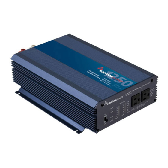
- Page 1 DC-AC owner's Please read this manual bEforE Manual Inverters installing your inverter PSE-12125A PSE-12175A PSE-12275A...
-
Page 2: Table Of Contents
Owner's MAnuAl | Index Section 1: Safety Instructions ................3 Section 2: General Information on Inverters ........... 6 Section 3: Characteristics of Sinusoidal AC Power ......... 9 Section 4: AC Power Distribution & Grounding ........... 10 Section 5: Limiting Electromagnetic Interference (EMI) ........14 Section 6: General Information on Lead Acid Batteries ......... -
Page 3: Safety Instructions
seCtIOn 1 | safety Instructions IMPORTANT SAFETY INSTRUCTIONS SAVe tHeSe inStRUctionS This manual contains important Safety and operating Instructions. Please read before using this unit. The following safety symbols will be used in this manual to highlight safety and information: WARninG! Indicates possibility of physical harm to the user in case of non-compliance. -
Page 4: Inverter Safety
seCtIOn 1 | safety Instructions Preventing Fire and explosion Hazards working with the inverter may produce arcs or sparks. Thus, the inverter should not be used in areas where there are inflammable materials or gases requiring ignition protected equipment. These areas may include spaces containing gasoline powered machinery, fuel tanks, battery compartments Precautions when Working with Batteries. - Page 5 seCtIOn 1 | safety Instructions connecting to Multi-Wire Branch circuits do not directly connect the hot side of the 120 VAc of the inverter to the two hot legs of the 120 / 240 VAc electrical breaker panel / load centre where multi-wire (common neutral) branch circuit wiring method is used for distribution of Ac power.
-
Page 6: General Information On Inverters
seCtIOn 2 | General Information on Inverters inVeRteR GeneRAl inFoRMAtion Why an inverter is needed The utility grid supplies you with alternating current (Ac) electricity. Ac is the standard form of electricity for anything that “plugs in” to the utility power. direct current (dc) electricity flows in a single direction. - Page 7 seCtIOn 2 | General Information on Inverters loads that Require “Surge Power” to Start resistive types of loads (like incandescent lamps, toaster, coffee maker, electric range, iron etc) do not require extra power to start. Their starting power is the same as their running power.
- Page 8 seCtIOn 2 | General Information on Inverters Power Rating of Microwaves The power rating of the microwave oven specifies its output or cooking power in watts. Microwaves are not very efficent devices – efficiency is around 50%. Therefore, its input power is almost 2x its output / cooking power.
-
Page 9: Characteristics Of Sinusoidal Ac Power
seCtIOn 3 | Characteristics of sinusoidal AC Power VoltAGe, cURRent, PoWeR FActoR, tYPeS oF loADS The voltage waveform of 120 VAc, 60 hz mains / utility power is like a sine wave (see fig 8.1, page 30). In a voltage with a sine wave-form, the instantaneous value and polarity of the voltage varies with respect to time and the wave-form is like a sine wave. -
Page 10: Ac Power Distribution & Grounding
seCtIOn 4 | AC Power Distribution & Grounding cAUtion! PleASe note tHAt tHe Ac oUtPUt connectionS AnD tHe Dc inPUt connectionS on tHeSe inVeRteRS ARe not connecteD (BonDeD) to tHe MetAl cHASSiS oF tHe inVeRteR. BotH tHe inPUt AnD oUtPUt connectionS ARe iSolAteD FRoM tHe MetAl cHASSiS AnD FRoM eAcH otHeR. - Page 11 For the 120 VAc, 60 Hz neMA 5-15R receptacles in PSe-12125A and PSe-12175A (f, Fig. 7.1), the current carrying conductor connected to the longer rectangular slot is iso- lated from the metal chassis of the inverter.
- Page 12 / earth ground and may produce electrical shock! GRoUnDinG oF PSe-12125A / PSe-12175A to eARtH oR to otHeR DeSiGnAteD GRoUnD for safety, the metal chassis of the inverter is required to be grounded to the earth ground or to the other designated ground (for example, in a mobile rV, the metal frame of the rV is normally designated as the negative dc ground).
- Page 13 5-15r receptacle and breaker to their front panel, it should be grounded as in the case of PSE-12125A and PSE-12175A i.e. connect an Awg #8 insulated stranded copper wire from the equipment grounding bolt to the earth ground connection (a connection that connects to the ground rod or to the water pipe or to another connection that is solidly bonded to the earth ground).
-
Page 14: Limiting Electromagnetic Interference (Emi)
seCtIOn 5 | limiting electro-magnetic Interference (eMI) The inverter contains internal switching devices which generate conducted and radiated electromagnetic interference (EMI). The EMI is more pronounced in inverters whose output voltage has modified sine wave form as modified sine wave form is composed of odd harmonics of the fundamental frequency (60 hz). -
Page 15: General Information On Lead Acid Batteries
seCtIOn 6 | General Information on lead Acid Batteries lead-acid batteries can be categorized by the type of application: Automotive service - Starting/lighting/Ignition (SlI, a.k.a. cranking), and deep cycle service. deep cycle lead Acid batteries of appropriate capacity are recommended for powering of inverters. - Page 16 seCtIOn 6 | General Information on lead Acid Batteries typical Battery Sizes Table 6.1 below shows details of some popular battery sizes: tABle 6.1: PoPUlAR BAtteRY SizeS Bci* Group Battery Voltage, V Battery capacity, Ah 27 / 31 gc2** * battery council International; ** golf cart Specifying charging / Discharging currents: c-Rate Electrical energy is stored in a cell / battery in the form of dc power.
- Page 17 seCtIOn 6 | General Information on lead Acid Batteries Table 6.2 below gives some examples of c-rate specifications and applications: tABle 6.2: DiScHARGe cURRent RAteS - “c-RAteS” "c-Rate" Discharge current in Amps = example of c-Rate ÷ capacity "c" in Ah Discharge time "t"...
- Page 18 seCtIOn 6 | General Information on lead Acid Batteries Lead-Acid Battery Chart - 80˚F / 26.7˚C 24V 12V 33.0 16.5 C/10 32.0 16.0 CHARGE C/20 31.0 15.5 C/40 30.0 15.0 29.0 14.5 28.0 14.0 27.0 13.5 26.0 13.0 C/100 C/20 25.0 12.5 C/10...
- Page 19 seCtIOn 6 | General Information on lead Acid Batteries Table 6.3 (page 18) shows that a 100 Ah capacity battery will deliver 100% (i.e. full 100 Ah) capacity if it is slowly discharged over 20 hours at the rate of 5 Amperes (50w out- put for a 12V inverter and 100w output for a 24V inverter).
- Page 20 seCtIOn 6 | General Information on lead Acid Batteries Inverters are provided with a buzzer alarm to warn that the loaded battery has been deeply discharged to around 80% of the rated capacity. Normally, the buzzer alarm is triggered when the voltage at the DC input terminals of the inverter has dropped to around 10.5V for a 12V battery or 21V for 24V battery at C-Rate discharge current of C/5 Amps and electrolyte temp.
- Page 21 seCtIOn 6 | General Information on lead Acid Batteries In the example given above, the 10.5V / 21.0V low battery / dc Input Alarm would trig- ger at around 80% discharged state (20% Soc) when the c-rate discharge current is c/5 Amps.
- Page 22 seCtIOn 6 | General Information on lead Acid Batteries Please consider using the following Programmable low battery cut-off / “battery guard” Models manufactured by Samlex America, Inc. www.samlexamerica.com bg-40 (40A) – for up to 400w, 12V inverter or 800w, 24V inverter bg-60 (60A) - for up to 600w, 12V inverter or 1200w, 24V inverter bg-200 (200A) - for up to 2000w, 12V inverter or 4000w, 24V inverter Depth of Discharge of Battery and Battery life...
- Page 23 seCtIOn 6 | General Information on lead Acid Batteries terminal of battery 3 is connected to the Positive terminal of battery 2. The negative ter- minal of battery 2 is connected to the Positive terminal of battery 1. The negative terminal of battery 1 becomes the negative terminal of the 24V battery bank.
- Page 24 seCtIOn 6 | General Information on lead Acid Batteries cAUtion! when 2 or more batteries / battery strings are connected in parallel and are then connected to an inverter or charger (See figs 6.3 and 6.4 given above), attention should be paid to the manner in which the charger / inverter is con- nected to the battery bank.
- Page 25 seCtIOn 6 | General Information on lead Acid Batteries The first step is to estimate the total Ac watts (w) of load(s) and for how long the load(s) will operate in hours (h). The Ac watts are normally indicated in the electrical nameplate for each appliance or equipment.
- Page 26 seCtIOn 6 | General Information on lead Acid Batteries BAtteRieS, AlteRnAtoRS AnD iSolAtoRS on VeHicleS / RVS It is recommended that for powering the inverter, one or more auxiliary deep cycle batteries should be used that are separate from the SlI batteries. The inverter should be powered from the deep cycle batteries.
-
Page 27: Layout, Controls & Indications
PSE-12275A: 5/16" bolt, 18 Threads Per Inch (TPI) i) Protective cover for (+) and (-) terminals j) grounding connection: PSE-12125A/PSE-12175A: M-5 bolt & wing nut PSE-12275A: 8mm hole with M-8 set screw. k) k1: 6P6c Modular Jack for optional remote... - Page 28 seCtIOn 7 | layout, Controls & Indications FRONT h (negative - BlAck) h (Positive - ReD) BACK Fig. 7.2. Layout: PSE-12275A 28 | SAMLEX AMERICA INC.
- Page 29 15A outlet g) opening for cooling fan exhaust h) dc Input Terminals: PSE-12125A/PSE-12175A: 11mm hole with M-8 set screw. PSE-12275A: 5/16" bolt, 18 Threads Per Inch (TPI) i) Protective cover for (+) and (-) terminals j) grounding connection: PSE-12125A/PSE-12175A: M-5 bolt &...
-
Page 30: Principle Of Operation
seCtIOn 8 | Principle of Operation The inverter converts 24V (nominal) dc voltage of the battery to 120V, 60 hz Ac voltage. The voltage conversion takes place in two stages. In the first stage, the 24V (nominal) dc voltage of the battery is converted to high voltage dc (155V to 170V) using high frequency switching and Pulse width Modulation (PwM) technique. - Page 31 seCtIOn 8 | Principal of Operation DeViceS tHAt MAY not oPeRAte on MoDiFieD Sine WAVe The output wave form of these inverters is a modified sine wave (see fig. 8.1, page 30). In a sine wave, the voltage rises and falls smoothly with a smoothly changing phase angle and also changes its polarity instantly when it crosses 0 Volts.
-
Page 32: Installation
seCtIOn 9 | Installation The success of a dc to Ac power inverter installation depends mainly on the methods and materials used for installation. Please read and comply with instructions given below. GeneRAl installation and Wiring compliance Installation and wiring must comply with the local and the national electrical codes and must be done by a certified electrician. - Page 33 seCtIOn 9 | Installation Mounting Position of the inverter The inverter may be mounted horizontally on the top of a horizontal surface or under a horizontal surface. The inverter may be mounted on a vertical surface only horizon- tally (the fan axis should always be horizontal i.e. the fan should not be pointing up or down).
- Page 34 seCtIOn 9 | Installation do not use unregulated solar panels to charge a battery. under cold ambient tem- peratures, the output of the solar panel may exceed 16.5 Vdc. Always use a charge controller between the solar panel and the battery. do not connect to a battery system with a voltage higher than 12 Vdc nominal.
- Page 35 Dc input terminals on PSe-12125A and PSe-12175A The dc input terminals on PSE-12125A and PSE-12175A have a tubular hole with a set screw (h, fig. 7.1). A suitable pin type of copper terminal should, therefore, be used on the cable end.
-
Page 36: Section 10: Operation
2 hot outputs (120 VAc split phases) and the neutral from the secondary of this transformer should be connected to the electrical breaker panel / load centre. Ac output connections - PSe-12125A / PSe-12175A These inverters use nEMA 5-15r receptacles (f, fig. 7.1) for connecting the Ac output to devices and appliances fitted with a nEMA 5-15P plug. - Page 37 “neutral”. Do not touch this conductor as it will be at an elevated voltage with respect to the metal chassis / earth ground and may produce electrical shock. Grounding of PSe-12125A / PSe-12175A to earth or to other Designated Ground Please see details regarding grounding under “Ac Power distribution and grounding”...
- Page 38 seCtIOn 9 | Installation when using the inverter in a building , connect a #8 Awg insulated stranded copper wire from the above equipment grounding bolt to the earth ground connection (a con- nection that connects to the ground rod or to the water pipe or to another connection that is solidly bonded to the earth ground).
-
Page 39: Operation
seCtIOn 10 | Operation PoWeRinG on tHe loADS After the inverter is switched on, it takes a finite time for it to become ready to deliver full power. hence, always switch on the load(s) after a few seconds of switching on the inverter. -
Page 40: Protections Against Abnormal Conditions
seCtIOn 10 | Operation current will increase. At the same time, the value of voltage at the dc input terminals will decrease due to internal voltage drop in the battery and also due to external voltage drop in the dc input cables. indications for normal operation when the inverter is operating normally and supplying Ac load(s), only the voltage and current/power lEd bar graphs will be on. - Page 41 seCtIOn 11 | Protections Against Abnormal Conditions voltage will continue to be available. This warning alarm indicates that the battery is running low and that the inverter will be shut down after sometime if the voltage at the inverter terminals further drops to 10V. The alarm will reset automatically when voltage rises above 10.5V.
-
Page 42: Troubleshooting Guide
seCtIOn 11 | Protections Against Abnormal Conditions Switch (a, fig 7.1 or 7.2), wait for 3 minutes and switch on again. note: If the unit goes into overload once again, remove all the loads, reset as above and switch on. If it goes into overload condition again without any load, it is defective. Please call Technical Support. - Page 43 seCtIOn 12 | troubleshooting Guide SYMPtoM low Ac output voltage and the input current lEd bar graph (d, fig. 7.1 or 7.2) shows very high current (no buzzer alarm). PoSSiBle cAUSe low voltage at the dc input terminals and the load is close to the maximum allowable power.
- Page 44 seCtIOn 12 | troubleshooting Guide SYMPtoM There is no Ac output. The voltage lEd bar graph (d, fig. 7.1 or 7.2) shows dc input voltage reading of 15V (full bar graph is lighted up to the top rEd lEd). PoSSiBle cAUSe Shut-down due to high input dc voltage (>16.5V).
- Page 45 seCtIOn 12 | troubleshooting Guide SYMPtoM buzzer alarm is sounded. red over Temp lEd is on (b, fig. 7.1 or 7.2). There is no Ac output. PoSSiBle cAUSe Shut-down due to over temperature because of fan failure or inadequate cooling as a result of high ambient temperature or insufficient air exchange. Remedy: 1.
-
Page 46: Specifications
13 | specifications PARAMeteR PSe-12125A PSe-12175A PSe-12275A oUtPUt ouTPuT VolTAgE 120VAc +5% / - 10% ouTPuT frEQuEncy 60hz ± 5% 60hz ± 5% 60hz ± 5% ouTPuT VolTAgE wAVEforM Modified Sine wave MAXIMuM conTInuouS AcTIVE PowEr ouTPuT (PowEr 1250 w*... -
Page 47: Remote Control
13 | specifications PARAMeteR PSe-12125A PSe-12175A PSe-12275A InTErnAl dc SIdE fuSES Automotive Type ATc, 32V 175A 280A 360A (35A x 5 pcs.) (35A x 8 pcs.) (30A x 12 pcs.) inPUt AnD oUtPUt connectionS dc InPuT connEcTIonS Terminal with 11 mm diameter tubular 5/16”... -
Page 48: Warranty
2 YeAR liMiteD WARRAntY PSE-12125A, PSE-12175A, PSE-12275A manufactured by Samlex America, Inc. (the “war- rantor“) is warranted to be free from defects in workmanship and materials under normal use and service. The warranty period is 2 years for the united States and canada, and is in effect from the date of purchase by the user (the “Purchaser“). - Page 49 nOtes SAMLEX AMERICA INC. | 49...
- Page 50 nOtes 50 | SAMLEX AMERICA INC.
- Page 51 nOtes SAMLEX AMERICA INC. | 51...
- Page 52 Information Toll Free Numbers Ph: 800 561 5885 Fax: 888 814 5210 Local Numbers Ph: 604 525 3836 Fax: 604 525 5221 Website www.samlexamerica.com USA Shipping Warehouse Kent WA Canadian Shipping Warehouse Delta BC Email purchase orders to orders@samlexamerica.com 11001-PSE-12125A-12175A-12275A-0414...
Need help?
Do you have a question about the PSE-12125A and is the answer not in the manual?
Questions and answers