Table of Contents
Advertisement
Quick Links
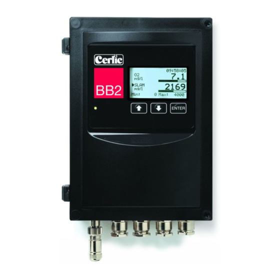
BB2 Central Unit
BB2 is the central unit for the Cerlic sensors. The measured value is converted to a
linearized 4-20mA output signal. The BB2 allows the user to easily adjust settings
and serves as a display for the measured output. The central unit also includes
communication protocols for connection to various input systems.
2009-03-04
C50A5EN10
Advertisement
Table of Contents

Related Manuals for Cerlic BB2


Summary of Contents for Cerlic BB2
- Page 1 BB2 Central Unit BB2 is the central unit for the Cerlic sensors. The measured value is converted to a linearized 4-20mA output signal. The BB2 allows the user to easily adjust settings and serves as a display for the measured output. The central unit also includes communication protocols for connection to various input systems.
-
Page 2: Table Of Contents
Introduction ......................22 Module Overview ....................22 Mounting in the 4-20 mA module in the BB2 control box ........23 Wiring Connections....................23 Getting started with the 4-20 mA module ............... 24 Technical specification for the 4-20mA module............24... -
Page 3: Introduction
All configuration of BB2 and connected sensors are done in menus, when a menu is opened on the display, the analog outputs of BB2 are frozen in order not to cause an alarm in the control system during calibration or while parameters are being changed. -
Page 4: Installation And Start-Up
Note date sign. Unpacking the BB2 control box Unpacking the sensor Refer to the sensor manual Mounting of BB2 control Mounting of sensor Refer to the sensor manual Electrical installation of 8 - 12 BB2 control box Electrical installation of... -
Page 5: Unpacking The Bb2 Control Box
Damages If damages occurred during shipment, immediately contact the shipping company and the Cerlic representative. The shipment should be returned only after an return authorization number has been issued by Cerlic or representative. Packaging The original packaging is designed to protect the equipment and should be used for storage or if the product must be returned. -
Page 6: Mounting Of Bb2 Control Box
Figure 1 Connection of BB2 Control box with two sensors and two flushing valves Wiring Connections BB2 is connected to power using a 3-lead cable approved for the rated current and voltage. We recommend that power be connected with an external on/off switch. - Page 7 We suggest using a shielded twisted pair AWG20 (0.5mm / 0,2 inch²) cable to connect the BB2 box to another system. If both outputs are connected to the same system a double twisted pair cable may be used. Make sure the shield is properly grounded according to good EMC practice.
- Page 8 When more than two sensors are connected to the BB2 control box, an extra 4-20 mA module or a Field Bus communication module must be installed in the BB2 control box to transfer the measuring results to a SCADA or DCS system.
-
Page 9: Jumper Settings
Jumpers on BB2 Analog outputs The two analog outputs of BB2 are default active, sourcing 4-20 mA into a load of maximum 450 ohms. They are galvanic isolated from the rest of the system, but the two channels use a common ground. Channel 2 can be jumpered to be passive, and fully isolated sink 4-20 mA from an external supply of max 24V DC, by changing JP1 and JP7. -
Page 10: Digital Inputs
Digital Inputs The three digital inputs are using BB2’s internal 24 VDC. To use an external 24 VDC source, galvanic isolated from the rest of the system (e.g. from a DCS or control system), the inputs need to be jumpered. These inputs can be used for selecting calibration for sensors having more than one calibration curve by setting up the sensor to use an external calibration. -
Page 11: Program Download
Any change of these jumpers will void the warranty. 10. Relay outputs BB2 has two relay outputs, configurable for Alarm or Cleaning. The relays can be used as Dry Contacts. Figure 3. This drawing can also be found on the inside of the front door. -
Page 12: Connection Of Automatic Flushing
11. Connection of automatic flushing Many of the sensors are equipped with built-in cleaning. The cleaning function is controlled by the BB2 control box relays. A solenoid valve is connected to relay contact 1 or 2, which must be configured in the sensor menu. -
Page 13: Alarm Limits
When a measured value goes above a high alarm limit or goes below a low alarm limit an alarm is triggered, and an alarm window is displayed on BB2 telling what sensor and reason caused the alarm. If a second alarm occurs a second line is added in the window. -
Page 14: Operational Interface
The layout of the main display varies depending on the number of sensors connected. BB2 can handle up to 4 sensors. The slots in the menu are numberd top down from 1 to 4. The first line of the display always shows the internal clock. Slots without a sensor connected are shown with the text No Transmitter . -
Page 15: Menu Topology
There are menus to configure BB2 and its sensors, they are divided in two branches, each having a set of submenus: 1. BB2 menu, to make changes to the setup of the BB2 control box. It is selected by pressing and ENTER simultaneously for five seconds. -
Page 16: Changing Values In The Menus
BB2 is looking for new sensors. This is indicated with a star between the header and the time in the main menu. BB2 has found a new sensor that it is trying to identify. This is indicated with a rotating line between the header and the time in the main menu. -
Page 17: Messages
Total Reset, Disconnect transmitter cable for 10 sec and reconnect. BB2 has done a total reset, the sensor database is emptied. If a total reset is done with any sensor attached to the BB2, the sensor must be disconnected for a while to be recognized by BB2. -
Page 18: Menus For The Bb2 Control Box
14. Menus for the BB2 control box Press and ENTER simultaneously for five (5) seconds to enter the BB2 Menu. Sensor menus are different for each type of sensor, and are entered by pressing ENTER for five (5) seconds on selected sensor. Sensor menus are described in the various sensor manuals. - Page 19 Panel LED Green / Red. Box heat Off / On, read only. Service Locked service menu for Cerlic internal use. EMPTY SLOT Slot 1 “Yes” / “No”, clear slot 1 to be able to use it for new sensor. Slot 2 “Yes”...
-
Page 20: Getting Started
Slots with no sensor currently connected can be freed in the BB2 menu. If a sensor is added to slot 1 or 2, BB2 will ask if the corresponding 4-20 mA output shall be used (unless it is already used by another sensor). The use of an output can be changed in the sensor setting menu. -
Page 21: Technical Specifications For The Bb2 Control Box
16. Technical specifications for the BB2 control box Manufacturer Cerlic Controls AB, Sweden Name Measurement See drawing in section 17 Enclosure NEMA4 (IP65) Weight 1,3 kg (2.8lbs) Supply voltage 85 – 250 V AC, 50 – 60 Hz Fuse 3.15 A Slow 250V 4 x 20mm Power Usage 20 Watts (0.180 Amps @ 110V) -
Page 22: Appendix 1, Optional 4-20 Ma Output Module
APPENDIX 1, Optional 4-20 mA Output module Introduction The BB2 4-20mA module is used to expand the BB2 central unit with two 4-20mA loops. It is assumed that the user is familiar with the BB2 and 4-20mA technology. Module Overview The module has two active 4-20mA outputs. -
Page 23: Mounting In The 4-20 Ma Module In The Bb2 Control Box
Mounting in the 4-20 mA module in the BB2 control box The 4-20mA module shall be mounted in a BB2 control box. Make sure the power to the control box is switched off before mounting the module. Connect yourself and the control box chassis to protective ground before opening the antistatic package of the module to avoid static discharges that can damage the module or the box. -
Page 24: Getting Started With The 4-20 Ma Module
• Connect the mA loops, negative line to screw terminal 1, and 3, positive to terminal 2, and 4. • Switch on the power to the BB2 box and check that the module identifies itself in the BB2 menu under Settings / Exp.module.
Need help?
Do you have a question about the BB2 and is the answer not in the manual?
Questions and answers