Table of Contents
Advertisement
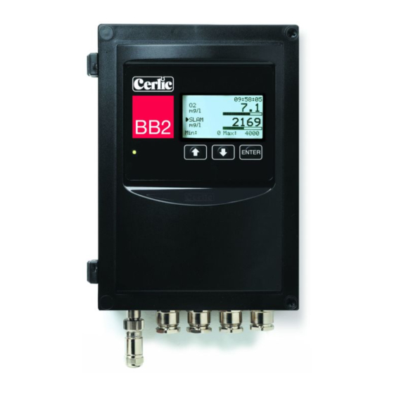
BB2 Control Box
BB2 is the control box to which most Cerlic sensors can be connected. The
measured signal is converted to a linearized 4-20mA output signal. The BB2 allows
the user to easily adjust settings and serves as a display for the measured output. The
unit also includes communication protocols for connection to various input systems.
2002-11-18
MANE11/02 VER2.00
Advertisement
Table of Contents

Related Manuals for Cerlic BB2


Summary of Contents for Cerlic BB2
- Page 1 BB2 Control Box BB2 is the control box to which most Cerlic sensors can be connected. The measured signal is converted to a linearized 4-20mA output signal. The BB2 allows the user to easily adjust settings and serves as a display for the measured output. The unit also includes communication protocols for connection to various input systems.
-
Page 2: Table Of Contents
14. Menus for the BB2 control box................15 15. Getting started .....................17 16. Technical specification for BB2 control box............18 Optional parts for BB2 control box: ..............18 17. Dimensions ......................19 APPENDIX 1, Instructions for EMC .................20 APPENDIX 2, Connection of shielded cable to fitting ..........22 APPENDIX 3, shielded cable without fitting .............23... -
Page 3: Introduction
Twice a minute the unit looks for unknown sensors, if one is found, BB2 will find out the type and serial number, and open up a dialog box to let the operator select what slot to use for the new sensor. -
Page 4: Installation And Start-Up
Note date sign. Unpacking the BB2 control box Unpacking the sensor Refer to the sensor manual Mounting of BB2 control Mounting of sensor Refer to the sensor manual Electrical installation of 8 - 12 BB2 control box Electrical installation of... -
Page 5: Unpacking The Bb2 Control Box
DAMAGES If damages occurred during shipment, immediately contact the shipping company and the Cerlic representative. The shipment should be returned only after an return authorization number has been issued by Cerlic or representative. PACKAGING The original packaging is designed to protect the equipment and should be used for storage or if the product must be returned. -
Page 6: Mounting Of Bb2 Control Box
Figure 1 Connection of BB2 Control box with two sensors and two flushing valves Wiring Connections BB2 is connected to the power using a 3-lead cable approved for the rated current and voltage. We recommend that the power be connected with an external on/off switch. - Page 7 We suggest using a shielded twisted pair AWG20 (0.5mm ) cable to connect the BB2 box to another system. If both outputs are connected to the same system a double twisted pair cable may be used. Make sure the shield is properly grounded according to good EMC practice.
-
Page 8: Jumper Settings
Jumpers on BB2 ANALOG OUTPUTS The two analog outputs of BB2 are default active, sourcing 4-20 mA into a load of maximum 500 ohms. They are galvanic isolated from the rest of the system, but the two channels use a common ground. Channel 2 can be jumperd to be passive, and fully isolated sink 4-20 mA from an external supply of max 24V DC, by changing JP1 and JP7. -
Page 9: Digital Inputs
DIGITAL INPUTS The three digital inputs are default using BB2’s internal 24 VDC, but can be jumpered to use an external 24 VDC source, galvanic isolated from the rest of the system (e.g. from a DCS or control system). These inputs can be used to control the selection of calibration curve for sensors having more than one. -
Page 10: Relay Outputs
10. Relay outputs BB2 has two relay outputs, configurable for Alarm or Cleaning. The relays can be used as Dry Contacts, 24 VDC output, or Mains AC output by setting jumpers according to figure 3. We do not recommend using 24 VDC outputs to drive solenoids. -
Page 11: Connection Of Automatic Flushing
The air or liquid is controlled with a solenoid valve that is wired to the BB2 control box relays. The solenoid valve is connected to relay contact 1 or 2, which must configure or setup in the sensor menu. -
Page 12: Operational Interface
Menus that are inactive for more than five minutes are automatically closed and the BB2 control box returns to the Main Menu. A menu is not considered to be inactive if a value is being edited or a function, e.g. calibration, is carried out. The back- light of the display is switched off at the same time, it is switched back on by pressing any button. -
Page 13: Menu Topology
There are menus to configure BB2 and its sensors, they are divided in two branches, each having a set of submenus: 1. BB2 menu, to make changes to the setup of the BB2 control box. It is selected by pressing and ENTER simultaneously for five seconds. -
Page 14: Changing Values In The Menus
All selected changes are implemented immediately and measuring is continuous. DIALOGS The BB2 sometimes shows a small dialog box containing a message. Sometimes at the bottom of the dialog box there is a message that says, “ENTER”. This indicates that the dialog will be confirmed and consequently disappears when the ENTER key is pressed. -
Page 15: Menus For The Bb2 Control Box
14. Menus for the BB2 control box Press and ENTER simultaneously for five (5) seconds to enter the BB2 Menu. Sensor menus are different for each type of sensor, and are entered by pressing ENTER for five (5) seconds on selected sensor. Sensor menus are described in the various sensor manuals. - Page 16 Panel LED Green / Red Box heat Off / On, read only Ø There may or may not be an additional Cerlic internal submenu that is not documented, and that may change without notice Empty Slot slot 1 Forget the previously installed transmitter in slot 1...
-
Page 17: Getting Started
30 seconds for the sensor to initialize and be identified. Changes to the settings can not be made until the BB2 control box has recognized the sensor. When recognized, the sensor will appear in the display mode. -
Page 18: Technical Specification For Bb2 Control Box
P/N 31204049 or solenoid valves w/ u-bolts, US version 33 ft. (10m) cable for. Connection cable with plug- in. P/N 20805510 Y-Splitter for two sensors to one BB2 control box P/N 21505534 Solenoid valve for flushing P/N 11705516 - 18 -... -
Page 19: Dimensions
17. Dimensions - 19 -... -
Page 20: Appendix 1, Instructions For Emc
APPENDIX 1, Instructions for EMC General EMC Requirements In order to ensure the instrument’s capability to fulfil the EMC requirements, no other components, parts or accessories other than those specifically mentioned in the instructions or this appendix may be removed, replaced or connected to the instrument. Devices marked with a CE-label must only be connected to intended transmitter’s. - Page 21 Installation Rekommendations Keep signal cables and power supply cables as far apart as possible. Cable grooves separating signal cables and power supply cables are strongly recommended. If signal cables and power supply cables cross, they should intersect perpendicular to one another. Signal and power supply cables should not be running parallel to one another in instrument cabinet inlets.
-
Page 22: Appendix 2, Connection Of Shielded Cable To Fitting
APPENDIX 2, Connection of shielded cable to fitting Illustration 1: Cable with fitting details 1. Insert the cable through fitting (2), washer (3), rubbersleeve, (4) and washer (5). 2. Remove 90 mm (L1) of the cable covering. 3. Strip the end of the signal wires. The stripped ends should be approx. 7 mm (L2). Illustration 2: Connection of the cable -shield to the washer 4. -
Page 23: Appendix 3, Shielded Cable Without Fitting
APPENDIX 3, shielded cable without fitting Illustration 1: Shielded cable with plait. Remove to 90 mm (L1) of the cable covering Tear the cable shield open and twine it to a plait (2) Cut the signal wires to shortest possible length (L1) and add 10mm for L2. L1 should not be more than 25 mm. -
Page 24: Appendix 4, Extending Shielded Cable
APPENDIX 4, Extending Shielded Cable Open the enclosures lid on the shielded box and fasten the box where appropriate. Illustration 1: Cables with shield and fitting. Put the fitting (2) and container (3) on the sensor cable. Peel the covering off the cable (1) to L1 (90 mm). Cut the cable shield (6) to 12 mm and fold it back over the O-ring (5) to the edge (4).
Need help?
Do you have a question about the BB2 and is the answer not in the manual?
Questions and answers