Table of Contents
Advertisement
Quick Links
Advertisement
Table of Contents

Related Manuals for Bodytastic B22.3

Summary of Contents for Bodytastic B22.3
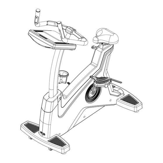
- Page 1 B22.3 BIKE ASSEMBLE INSTRUCTION INDEX...
-
Page 2: Table Of Contents
PART LIST ........................2 SCREW BAG ........................ 3 ASSEMBLE STEPS ...................... 4 The operation instruction of electronic meter .............. 10 4.1. Electronic meter structure ................11 Display page introduction ................... 13 5.1. Simple user interface: ..................13 5.2. Startup page ..................... 13 5.3. -
Page 3: Part List
1. PART LIST ITME Description ITEM Description frame Stuff holder seat Lower computer decorative cover Control tube Flask holder Handle bar tube Screw head cover computer Screw bag Control tube decorative cover Power wire Computer decorative cover front 2015/3/9V1.1+V1.1... -
Page 4: Screw Bag
2. SCREW BAG ITME Description ITEM Description Truss cross self-tapping screw Φ4x10 Cks hex screw M8xP1.25x25 Truss cross self-tapping screw Φ4x12 Spring washer M8 Flat washer Φ8xΦ12x1.0t Truss cross screw M4xP0.7x12 Truss cross self-tapping screw Φ4x15 Cks hex screwM8XP1.25X20 Spring washer M8 CABLE transferring head Truss cross screw M5xP0.8x10 K13 L shaped hex wrench+cross screwdriver... -
Page 5: Assemble Steps
3. ASSEMBLE STEPS STEP 1 ASSEMBLE FRAME AND SEAT Insert seat(B) into frame(A) as the arrow showing and fix them. 2015/3/9V1.1+V1.1... - Page 6 STEP 2 ASSEMBLE FRAME AND CONTROL TUBE Make the control wire of frame through control tube, then tighten control tube(C) on frame(A) with hex screw(K01), spring washer(K02) and flat washer(K02) as the figure showing. 2015/3/9V1.1+V1.1...
- Page 7 STEP 3 ASSEMBLE CONTROL TUBE AND CONTROL TUBE DECORATIVE COVER Tighten control tube decorative cover(F) with truss cross screw(K07) & truss cross self-tapping screw(K09) as figure showing, then cover the screw head cover(K). 2015/3/9V1.1+V1.1...
- Page 8 STEP 4 ASSEMBLE CONTROL TUBE AND HANDLE BAR TUBE Pull out the wires in handle bar tube(D) and make it through control tube(C), then tighten handle bar tube(D) on control tube(C) with hex screw(K04), spring washer(K05). : Lower control wire : Network cable : TV cable lower : Lower hand grip pulse wire...
- Page 9 STEP 5 ASSEMBLE COMPUTER AND CONTROL TUBE Connecting wires of computer(E) and the wires outing from control tube(C), then tighten computer(E) on control tube(C) with truss cross screw(K06). : Hand grip instant key connecting wire upper : Hand grip instant key connecting wire upper : Network connecting cable upper : TV cable : Upper control wire...
- Page 10 STEP 6 ASSEMBLE COMPUTER DECORATIVE COVER, FLASK HOLDER AND COMPUTER CONTROL TUBE Tighten computer decorative cover front(G) on control tube(C) with truss cross screw(K07), and fix stuff holder(H) with truss cross self-tapping screw(K08). Then tighten flask holder(J) on control tube(C) with truss cross screw(K10). At last, fix lower computer decorative cover(I) on computer(E) with truss cross self-tapping screw(K11).
-
Page 11: The Operation Instruction Of Electronic Meter
4. The operation instruction of electronic meter This machine can provide a simple and easily operated electronic meter. Users can input personal data by the electronic meter and set each exercise target. 2015/3/9V1.1+V1.1... -
Page 12: Electronic Meter Structure
4.1. Electronic meter structure Information condition Display each condition information before display exercise, during exercise and after exercise. area The screen area has touch function. On the screen, there are operation keys for each page. Except for pressing once, part keys support long Touch time pressing, finger drag and rotating. - Page 13 (1) If the electronic meter is in setting page and if press this key, the electronic meter can return to standby page. (2) If the electronic meter is in optional page of exercise storage device and if press this key, the electronic machine can return to standby page.
-
Page 14: Display
device. Nike+ function. The air The air outlet angle can be adjusted by hand. outlet holes of 5. Display page introduction 5.1. Simple user interface: The simple and obvious buttons and icons will assist users to operate as the users wish to finish all settings and the control during exercise. -
Page 15: Standby Page
There is a commonly existed status column at the Top right of the picture to assist users to make an inspection at any time. Wi_fi signal intensity It is used for confirming the online quality of wireless network of the electronic meter. -
Page 16: Program Control Set Page
5.5. Program control set page 5.5.1. Choose any program control in standby page, apart from Quick start, and then enter into the set page of the program control. 5.5.2. Input the age, weight, gender…of the user in specific program control, to be substituted into the computational formula of the SPC. - Page 17 CSAFE: A set of exercise management system developed by FitLinxx is one of the specifications widely accepted by fitness industry. The gym shall add FitLinxx memberships and server appliance shall be installed. Use RJ45 network cable to achieve the online and data synchronism with electronic meter. Exercise value of fitness equipment that uses CSAFE function can be accumulated.
-
Page 18: Pages Of The Exercise
Nike Plus: For a set of exercise management system developed by Nike, the user shall be equipped with Apple device that has Nike+iPod receiver established inside, such as iPod touch 4, Nano 6, and iPhone 4. Step.1 Connect with Apple device by iPod transmission line established inside the electronic meter. - Page 19 5.7.1. Enter the page of the exercise by the mode of Quick start or program control, and there are five areas, A/B/C/D/E. 5.7.2. Instruction of display areas A-1 area: The information area of motion state can display five common states of motion, including distance value, heartbeat value, calorie value, time and lifting outline (shown in the form of column diagram).
- Page 20 E area: the operating keys as following: Cool down Enter into 3-min-cool down program by manual operation. Every 1 min passes; the speed value will decrease 50% automatically. Lifting will return to 0 section, when the time is zero, run end. Skip Press this button for cancel, when in warm or cool down program.
- Page 21 5.7.3. Multimedia function facebook: Connect the facebook browse specially designed, remove unnecessary links, wall information of the user is displayed. Or press sharing key, the current exercise summary will be rapidly posted on the wall. ※ Privacy protection: The system will end the FB account which is logged in by the users and turn to the standby page, or remove the safety key, the FB account will be logged out automatically.
- Page 22 iPod/iPhone: Connect the iPod specially designed; insert the connecting line of iPod of electronic meter into Apple device of the user. The system will begin to read files of (Loading) Apple device and the files will be displayed in the central region of the picture.
- Page 23 ※ 8Pin lighting connector is the official updated module after 2013 from Apple company, and the new module without the function of depositing and withdrawing of video and nike+ for the exterior equipment, but the function of supporting charging and depositing and withdrawing of video is maintained.
-
Page 24: Exercise Course Page
down to confirm, then press image pattern, the film will be loaded, and the film will be played after being loaded. The image is in the center of the picture, there is play progress bar in the bottom. Press the center to pause or recover the play. Press ← key, return to last film menu, press └... - Page 25 Green lights mean completion, no lights means no upload or uploading unsuccessfully. Some special program control such as soldier stamina rating will display corresponding scores and rating levels in accordance with age and finish time of users after finishing appointed target. ...
-
Page 26: Heart Detection Introduction
More detailed information related to how to upload and trace your stamina training process could be searched out on Garmin ANT Agent site. 6. Heart Detection Introduction According to related studies, maintaining a stable heart rate in exercise is the best tempered manner for monitoring exercising strength and reaching the maximum strength, which our electronic meter could meet the demand. -
Page 27: Regional Heart Rate Exercise
6.2. Regional heart rate exercise Set ideal heart rate range or region, and start aerobic exercise and exercise of enhancing cardiovascular functions. The following table is a heartbeat display image of age and corresponding target heart rate. Regional heart rate exercise includes the following 5 kinds of modes: •... -
Page 28: Overview Of Sports And Fitness Program
slowly, the slope will maintain current angle, and all exercise values will be saved temporarily for 15 seconds. Continue key can be pressed within 15 seconds to recover, the speed will return to status before lifting; The program can terminate automatically and return to standby page when pause status exceeds 15 seconds. - Page 29 1. It is an automatic program of LEVEL change and the pre-programmed default value. The LEVEL is 20. Scroll the contour plot to make changes of each phase in details. 2. After the end of the program, you may manually adjust the LEVEL. A change is available for each stage.
- Page 30 finger to create customized procedure. HR Control Exercise body strength with the changes of heart rate. Use of chest sensor or heart rate sensor equipped on the handrail during exercise is required; otherwise the program control of this workout will be invalid. Fat Burn Heart Rate 1.
- Page 31 Cardio Heart Rate 1. During the heartbeat exercise, the heart rate is changed between the two target heart rates (65%, 85%), alternatively. 2. The movement of program has the same requirements as other HRC program. 3. Program figure (taking 40-year-old user as the example): HRmax Diagram Target Heart Rate 1.
- Page 32 2. The movement of program has the same requirements as other HRC program. Hill Heart Rate 1. The program is composed by four target heart rates. Of which, the target rate of three changes are 70%, 75%, and 80%, respectively. The rest remains at 65% as the minimum.
-
Page 33: Fitness Test
Diagram of Heart Rate Interval FITNESS TEST This model is aimed to get the strength of heart rate of the user in the tested movement process by substituting the heartbeat values, before and after the test, into the comparison table. - Page 34 RESULT CONSTANT WATT This model is aimed for fixed resistance target workout. During the exercise period, the LEVEL increases and decreases automatically with the current RPM, allowing the user to achieve the demands of the target value set, 25W ~ 400W. Set WATT and time.
-
Page 35: Virtual Active
increased or decreased automatically. Virtual Active 1. The virtual reality is from movie which is taken by professional movie company and the copyright is legal. And the map includes resorts from all over the world, the national park, streets or mountains. And the film is showed in first person’s view to make the users be in the virtual reality. -
Page 36: Program Set
windows will be close. These windows will recover after pressing once again. 9. The exercise information above could be dragged down. 8. Program Set 8.1. Enter and Exit Engineer Mode Enter: After switch on the upright bike, press logo for about 5 seconds to enter engineer mode. -
Page 37: Time Zone Setting
MCU Version: the version of the I/O firmware of the system Kernel Version:version of the core program of the system BG Service:null:means no backend service ready:means backend service is ready not ready:means backend service is available but abnormal ... -
Page 38: Wi-Fi Setting
8.7. Wi-fi setting Switch to on position, the system will detect available wi-fi connection. db means the signal strength, the smaller the better (it is advised to be lower than 50db). Please choose the wi-fi connection, enter password, press connect or Done, wait for connection. Once “connected” (red color)shows up, the connection is completed. -
Page 39: Value Setting
Media UPDATE:Update for the visual reality film, please refer to the file about the update for software for details. BG Service UPDATE:Update backend service, please refer to the file about the update for software for details. 8.10. Value Setting ... -
Page 40: Others
“ATV” and “DTV” cannot coexist at the same time, when the signal change, please set and scan again. After scanning, the some channel can be executed as “ locked channel” and this channel will not appear in the TV mode any more. 8.13.
Need help?
Do you have a question about the B22.3 and is the answer not in the manual?
Questions and answers