Table of Contents

Summary of Contents for Kwik-Way 103
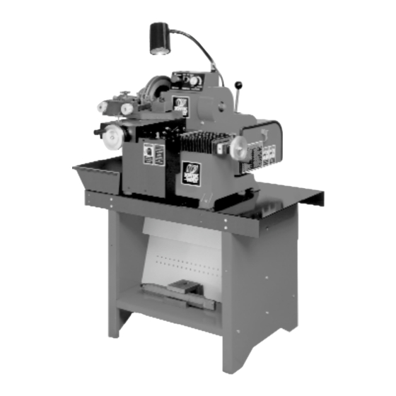
- Page 1 Multi-Speed Combination Brake Lathe Instruction Manual and Parts List Kwik-Way Products Inc. Copyright © 2005, All Rights Reserved Equipment, specifications, options and accessories subject to change without notice Part #...
- Page 3 Kwik-Way will repair and/or replace, free of charge (FOB factory) all such defective parts, only when returned to factory with shipping charges prepaid. This warranty does not cover parts and supplies consumed in normal operation of the machine.
- Page 5 Upon taking delivery of your machine, carefully inspect the assembly before removing the crating and packing materials. If evidence of damage exists, contact the shipper and Kwik-Way Products Inc . immediately. Although Kwik-Way Products Inc . is not responsible for damage incurred during transit, you will be provided assistance in preparation and filing of any necessary claims.
-
Page 7: Standard & Optional Equipment
103 Multi-Speed Brake Lathe STANDARD & OPTIONAL EQUIPMENT 103 Multi-Speed Combination Lathe 103-8680-30 115 V, 60 Hz, 1 Ph 103-8680-31 230 V, 60 Hz, 1 Ph 103-8680-32 230 V, 50 Hz, 1 Ph S TANDARD EQUIPMENT INCLUDED Part No. Description... - Page 8 103 Multi-Speed Brake Lathe Part # Description 804-8691-95 Hubless Adapter Set, Small Size for 1" Arbor, Bore Range 1.87"-3.00" (47.50 76.20 mm) 804-8691-93 Rotor Locator-RH 804-8659-61 Cone, 1.88x3.13 (47.63x79.38 mm) 804-8659-62 Spacer 804-8691-94 Locator Nut-RH 804-1251-10 Wrench, Spanner 804-8691-98 Hubless Adapter Set, Std Size for 1" Arbor, Bore Range 2.03"-3.93" (51.56-99.82 mm)
- Page 9 103 Multi-Speed Brake Lathe Part # Description 804-8665-47 Basic Bench, Heavy Gauge 22"Wx38"x26"L, (558.80x965.20 x 660.0mm) w/Lower Tool Board, Chip Tray, and Adapter Hooks 804-8410-33 341 Deluxe Bench, Heavy Gauge 22"Wx38"Lx71"H (558.80x965.20x1803.40mm) w/ 2 Tool Boards, Chip Tray, Adapter Hooks, and Arbor Rack...
-
Page 10: Safety First
The specifications put forth in this manual were in effect at the time of publication. However, owing to Kwik-Way Products’ policy of continuous improvement, changes to these specifications may be made at any time without obligation. SAFETY INSTRUCTIONS... - Page 11 Kwik-Way recommends the use of anti-skid floor strips on the floor area where the operator normally stands and that each machine's work area be marked off. Make certain the work area is well lighted and ventilated.
- Page 12 E L E C T R I C A L R E Q U I R E M E N T S The 103 is available in three electrical configurations: 115V, 60 Hz, 1 Ph; 230V, 60 Hz, 1 Ph; and electri- cals of 230V, 50 Hz, 1 Ph.
-
Page 13: Installation
POSITION MOTOR DRIVE BELT AND Figure 4 TENSION PROPERLY BEFORE USE 1. The 103 is shipped with all belts pro p e r l y tensioned with the exception of the motor drive 4 Groove Poly-V belt. The 103 was shipped with the motor drive belt off the motor drive pulley so Replacement Parts &... - Page 14 103 Multi-Speed Brake Lathe COMPONENT & CONTROL IDENTIFICATION 1. Disc Slide Handwheel (cross feed) 2. Spindle 3. Main Power Switch & Emergency Stop 4. Function Switch — selects the drum or disc slides 5. Feed Rate Control for both drum and disc 6.
-
Page 15: Specifications
Size22" x 38" x 71" (559 x 965 x 1803 mm) Weight ............................140 lbs. (64 kg) Kwik-Way is committed to product innovation and improvement and therefore reserves the right to change product specifications without notice Replacement Parts & Supplies - 800-553-5953... - Page 16 INSTALLATION OF ARBOR 1. The 1" diameter arbor is included with the 103 as standard equipment and is capable of handling work pieces up to 150 lbs. If the work piece is heavier the 150 lbs, it will be necessary to use the optional 2" Heavy Duty Arbor.
- Page 17 MAKE CERTAIN POWER SWITCH IS IN THE OFF POSITION before changing the spindle speed. 1. The 3 spindle speeds on the 103 are 60, 120, & 170 RPM’s. To select the desired speed, lift and turn the latch handle to open the belt access door (Figure 8). Loosen the belt tensioning lock by pushing down on the lever (Figure 9).
- Page 18 103 Multi-Speed Brake Lathe SELECTING THE FEED RAT E 1. The 103 features an infinitely variable feed on both the disc slide and the drum slide. This will allow the operator to totally control surface finish and machining time for drums and discs. Refer to chart below for the spindle speed/feed rate ratio to determine the optimum feed rate.
- Page 19 DRUM BAR TOOLING ASSEMBLY The 103 Drum Bar, Part Number 804-8671-10, is machined at both ends. The end of the bar with the machined slot and the two set screws is used for larger drums and flywheels. The end of the bar that is reduced in width is for machining small drums.
- Page 20 103 Multi-Speed Brake Lathe 1. HUBLESS DRUMS (Fig. 22) are mounted using 2 bell clamps of the same size, a tapered cone, a spring, and spacers. Make certain the mounting pads of the bell clamps are clean and free of nicks, burrs, etc.
- Page 21 103 Multi-Speed Brake Lathe 4. On smaller drums position the tool bar and bit at the outer edge of the drum to insure that the tool bar will not contact the spindle housing during machining. It may be necessary to use spacers to position the drum further out on the arbor to allow clearance for the tool bar.
- Page 22 103 Multi-Speed Brake Lathe P R E PARING DISCS ROTORS FOR MACHINING 1. Before machining, each disc rotor should be carefully inspected for scoring, rust, ridges (at the inner and outer circumference of the rotor) and hard spots. Any excessive wear or deformity should be noted and, if not within acceptable limits, the rotor should be replaced.
- Page 23 Figure 33 Four Rotor Bits are included with the 103. Install 2 in Twin Cutter. The rotor bits have three cutting edges -- make certain that the narrow side of the bit is on the top. This will allow for the proper clearance angle while machining.
- Page 24 103 Multi-Speed Brake Lathe MACHINING When machining thin, non-vented composite rotors, use the built-in dampener arms. When machining the thicker vented rotors, use the silencer band. Do not use both at the same time. 1. Manually adjust the traverse slide over until the Twin Cutter Arms are centered over the rotor.
- Page 25 103 Multi-Speed Brake Lathe FLYWHEELS 1. Mount the flywheel on the 1" arbor (Figure 43). It may be necessary to use a smaller optional centering cone if the pilot bore is smaller than 1.7" If the pilot bore of the...
- Page 26 103 Multi-Speed Brake Lathe GearFree™ SPINDLE DRIVE 1. The GearFree™ Drive System contains 4 sets of pulleys (Figure 46): 4 Groove Poly-V pulley ..Belt #804-1405-83 B 10 Groove Poly-V pulley ..Belt #804-8680-53 C 14 Groove Poly-V pulley ..Belt #804-8680-54 D Cogged timing pulley...Belt #804-8680-52...
-
Page 27: Maintenance And Service
1. DAILY: Clean all surfaces to remove chips and dirt. Use a brush or a shop vac. To prevent metal in machine bear- ings NEVER use compressed air to clean the 103 Brake Lathe. 1. WEEKLY Apply dry graphite lubricant to the dovetail ways. DO NOT use grease or oil on the ways or leadscrew since this collects chips and causes accelerated wear. - Page 28 103 Multi-Speed Brake Lathe 103 BRAKE LATHE ASSEMBLY FRONT VIEW Item Part No. Description Qty. 804-8680-39 Base (Mach) 804-8680-44 Spindle Housing Assembly 804-8681-23 Slide Assembly 804-8680-36 Control Box Assembly 804-8679-90 Outlet Box Assembly 804-8680-86 Motor Guard 804-8680-85 Pulley Guard 800-8014-71...
-
Page 29: Right Side View
103 Multi-Speed Brake Lathe RIGHT SIDE VIEW REAR VIEW Replacement Parts & Supplies - 800-553-5953... - Page 30 103 Multi-Speed Brake Lathe 103 RIGHT VIEW GearFree™ DRIVE Item Part No. Description Qty. Item Part No. Description Qty. 804-1405-24 Motor 1 HP 115-207 804-8680-72 Flanged Pulley Adapter 804-8680-57 Motor Mount Plate Assembly 000-0163-14 SHCS #10-32 x .500 804-8686-72 Washer Thrust...
- Page 31 103 Multi-Speed Brake Lathe 103 REAR VIEW GearFree™ DRIVE SECTION A-A Replacement Parts & Supplies - 800-553-5953...
-
Page 32: Main Assembly
103 Multi-Speed Brake Lathe MAIN ASSEMBLY Replacement Parts & Supplies - 800-553-5953... - Page 33 103 Multi-Speed Brake Lathe MAIN ASSEMBLY Item Part No. Description Qty. Item Part No. Description Qty. 000-4400-10 Handle 804-8681-22 Way Cover 804-8063-01 Acorn Nut, 5/16 804-8664-20 Motor Cover Guard 804-8663-24 Hand Wheel 804-8686-37 Drum Lead Screw 804-8679-65 Disc Slide Plate...
- Page 34 103 Multi-Speed Brake Lathe ITEM 45 ON MAIN ASSEMBLY DRAWING 804-8689-86 ROTOR FEED LOCK ASSEMBLY Item Part No. Description Qty. 000-0595-32 BHCS 10-32 x .500....1 804-8689-80 Knob ..........1 804-8689-83 Engagement Stem (Disc)...1 804-8097-68 Roll Pin, .062 x .500 ....1 804-8689-85 Flat Washer, 6mm .....1 804-8689-84 Spring ........1...
- Page 35 103 Multi-Speed Brake Lathe ITEM 57 ON MAIN ASSEMBLY DRAWING 804-8689-87 DRUM FEED LOCK ASSEMBLY Item Part No. Description Qty. 000-0595-32 BHCS 10-32 x .500....1 804-8689-80 Knob ..........1 804-8689-82 Engagement Stem (Drum)..1 804-8097-68 Roll Pin .062 x .500 ....1 804-8689-85 Flat Washer, 6mm .....1 804-8689-84 Spring ........1...
- Page 36 103 Multi-Speed Brake Lathe 103 FRONT VIEW CONTROL BOX ASSEMBLY Item Part No. Description Qty. 804-8680-40 Control Box 804-8607-40 Feed Rate Dial 804-8675-50 Function Switch 800-8675-49 Push/Pull Switch 800-8665-89 Fuse holder 800-8014-69 Strain Relief .230 800-8606-79 DC Controller 804-8653-31 BHCS #8-32 x .75...
- Page 37 103 Multi-Speed Brake Lathe 103 CONTROL BOX ASSEMBLY Replacement Parts & Supplies - 800-553-5953...
-
Page 38: Spindle Housing Assembly
103 Multi-Speed Brake Lathe 804-8680-44 SPINDLE HOUSING ASSEMBLY Item Part No. Description Qty. 804-8663-65 Seal-Front 804-8680-45 Spindle 804-8084-14 Bearing Cone 804-8084-15 Bearing Cup 804-8680-43 Spindle Housing 804-8680-50 Bearing Cup 804-8680-49 Bearing Cone 804-8680-84 Spacer 804-8663-71 Seal-Rear 804-8663-56 Locknut BH 07... - Page 39 103 Multi-Speed Brake Lathe TOOL BAR ASSEMBLY Item Part No. Description Qty. 804-8691-73 Tool Bar 000-0505-20 SSS .375-16 x .500 804-8030-07 SS .312-24 x .375 804-8691-74 Tool Bit Holder 000-0160-14 SHCS 8-32 x .625 804-3041-67 (Package of 3) 804-3041-71 Tool Holder Assembly...
- Page 40 103 Multi-Speed Brake Lathe 804-8686-34 DISC SLIDE LEAD SCREW NUT ASSEMBLY Item Part No. Description Qty. 804-8686-35 Leadscrew Nut Sleeve 000-1624-10 Thrust Washer 000-1624-00 Needle Bearing 804-8663-26 Nut Mount, Block 804-8663-27 Leadscrew Drive Gear 804-8668-34 SSS #10-32 x .18 804-8686-74 DRUM SLIDE LEAD SCREW NUT ASSEMBLY Item Part No.
- Page 41 103 Multi-Speed Brake Lathe 804-8663-40 GEAR LINK SHAFT ASSEMBLY Item Part No. Description Qty. 804-8665-51 Gear Shaft Assembly 804-8663-83 Oilite Bearing 804-8663-43 Gear Link Support 804-8663-38 Drive Sprocket 000-0482-91 SSS #10-32 x .25 804-1290-02 Oilite Thrust Washer Replacement Parts & Supplies - 800-553-5953...
- Page 42 103 Multi-Speed Brake Lathe 804-8691-68 DISC CLAW ASSEMBLY Item Part No. Description Qty. Item Part No. Description Qty. 804-8689-51 Micrometer Knob 804-8691-28 Knob Spacer 804-8689-52 Zeroing Sleeve 804-1407-54 Washer 804-8659-49 Feed Dial Label 804-2052-31 Shoe 000-7300-41 Woodruff #5 Key 804-8691-32...
- Page 43 804-8665-47 Place the four rubber pads in line with the four holes in the top BASIC BENCH of the bench. Using proper lifting equipment place the 103 Brake Lathe on top of the pads. NOTE: Does not include Items Fasten the lathe to the bench using the four 3/8-16 x 2.00 bolts, No.’s 5 &...
- Page 44 103 Multi-Speed Brake Lathe 804-8692-14 OUTBOARD SUPPORT ASSEMBLY 804-8691-92 Item Part No. Description Qty. 000-0105-53 HHCS 3/8-16 x 1.25 804-8030-61 Lock Washer - 3/16” 804-8690-92 Pillow Block Bearing 804-8682-67 Support Bearing Slide 804-8682-69 Locking Collar 804-8682-66 Base Weldment Stand 000-1035-35...
- Page 46 Kwik-Way Products Inc. 500 57th Street, Marion, IA 52302 USA 319-377-9421 319-377-9101 (FAX) 800-553-5953 www.kwik-way.com service@kwik-way.com Copyright © Kwik-Way Products Inc. 2005 All Rights Reserved...
Need help?
Do you have a question about the 103 and is the answer not in the manual?
Questions and answers