Table of Contents
Troubleshooting

Subscribe to Our Youtube Channel
Related Manuals for Genesis SHERLOCK 102

Summary of Contents for Genesis SHERLOCK 102
- Page 1 SHERLOCK 102/202 REFRIGERANT MONITOR Operations Manual Part # 44-0297 GENESIS INTERNATIONAL, INC. 1040 FOX CHASE INDUSTRIAL DR TEL: 636-282-0011 ARNOLD, MO 63010 FAX:636-282-2722 EMAIL:MAIL@GENESIS-INTERNATIONAL.COM WEB:WWW.GENESIS-INTERNATIONAL.COM...
-
Page 2: Table Of Contents
TABLE OF CONTENTS 1. SAFETY WARNINGS 2. INTRODUCTION 3. COMPONENT OVERVIEW Sherlock 102/202 Control Module Infrared Sensor 10-12 Solid State (CMOS) Sensor 13-14 Ventline Sensor High Pressure Ventline Sensor Electro-Chemical Ammonia Sensor Electro-Chemical Oxygen Depletion Sensor Strobe Light Horn and Strobe Combo... - Page 3 THIS PAGE INTENTIONALLY LEFT BLANK 44-00-0297 SHERLOCK102/202 REV. 4.1 05-02-15...
-
Page 4: Safety Warnings
SAFETY WARNINGS CAUTION , RISK OF ELECTRIC SHOCK!!! SHUT OFF ALL POWER TO CONTROL PANEL AND CONTROL CIRCUITS BEFORE OPENING ENCLOSURE DOOR AND PERFORMING SERVICE. CAUTION , RISK OF ELECTRIC SHOCK!!! RELAY CONTACTS MAY BE ELECTRIFIED ALTHOUGH CONTROL POWER TO PANEL IS SHUT OFF. ENSURE THAT ALL POWER IS DISCONNECTED BEFORE OPENING ENCLOSURE DOOR AND PERFORMING SERVICE CAUTION , IMPROPER CONNECTION OF EXTERNAL DEVICES... - Page 5 This manual has been checked for accuracy. However, due to new technology being made available, some changes may have been implemented to the control but not necessarily to this manual. If you have any questions regarding any discrepancies, please call Genesis customer service for clarification. 44-00-0297 SHERLOCK102/202 REV. 4.1 05-02-15...
-
Page 6: Introduction
(Please call Monitoring Panel Genesis Customer Support for more information). The SHERLOCK 102 and 202 Control Module is an ETL Infrared Sensor listed, hard wired, permanently mounted electronic control The SHERLOCK Non-Dispersive, Pyro-Electric Infrared Sensor... - Page 7 Analog Signal Generator (Factory Installed Option) reaction with oxygen molecules, thus producing a voltage drop The SHERLOCK 102 and 202 has an optional 4-20 mA analog across the cell. When the concentration of oxygen changes, output generator for each sensor. Either of these signals can be the voltage drop across the cell changes.
-
Page 8: Sherlock 102/202 Control Module
CONTROL MODULE SHERLOCK 102 / 202 OVERVIEW The SHERLOCK Monitoring System was designed to monitor CONTROL MODULE up to two SHERLOCK Refrigerant Gas Sensors, activating up to two alarms based upon user defined alarm level setpoints. The SHERLOCK is compliant with ASHRAE 15-2010 and Mechanical Code requirements for refrigerant gas monitoring. - Page 9 IR SENSOR (Also see manual 44-0295 IR Sensor (44-0221 Obsolete) ENCLOSURE RATING NEMA 3R Aluminum, Black Powder Coat The SHERLOCK Non-Dispersive IR Refrigerant Gas Sensor was designed to monitor for the presence of refrigerant gases DIMENSIONS 12.86 x 4.8 x 2.44 within an enclosed space.
- Page 10 EACH SENSOR. FAILURE TO DO SO COULD VOID Genesis for a specifi c manual or technical advice before making THE WARRANTY. any changes to the potentiometer positions. The Sherlock IR Infrared Sensor components description and use.
- Page 11 IR SENSOR 44-00-0297 SHERLOCK102/202 REV. 4.1 05-02-15...
- Page 12 The CMOS sensor will detect concentrations of gasoline, diesel, and propane exhaust and fumes from solvents, paints, cleansers, and others (Please call Genesis Customer Support for more information.) The stated accuarcy is a best case and some refrigerant blends can be off as much as 100% of the Sherlock Control ppm reading.
-
Page 13: Mounting Instructions
For Halocarbon refrigerants (heavier than air), such as R11, Operating Range. R22, R123, R-134a, etc..., place the sensor Genesis part number 82-0100 (60-0113) or 82-0101(60-0128) 18 to 24 inches off the The Sherlock CMOS Sensor has an effective range of 0 to 1000 floor. -
Page 14: Ventline Sensor
VENTLINE SENSORS OVERVIEW The SHERLOCK High Pressure Ventline Refrigerant Gas Sensor OVERVIEW was designed to detect the presence of high concentrations of The SHERLOCK VENTLINE REFRIGERANT GAS SENSOR refrigerant gas in the vent lines of refrigeration systems. The (VENTLINE) was designed to detect the presence of high con- sensor warns the user to investigate for possible leaks in relief centrations of refrigerant gas in the vent lines of refrigeration valve or to check the systems for overpressure. -
Page 15: Electro-Chemical Ammonia Sensor
LED 2 - LED2 is the RED LED that is on the sensor main board. from solvents, paints, cleansers, and others (Please call Genesis It will fl ash every second when there is power to the board and Customer Support for more information). -
Page 16: Electro-Chemical Oxygen Depletion Sensor
OXYGEN DEPLETION SENSOR (Please see manual # 44-0342 "Oxygen Depletion Sensor" for LIFE EXPECTANCY Factory Recommendation more information and the location of components.) of Replacing the sensor every 5 years The SHERLOCK OXYGEN DEPLETION SENSOR (O 2 SENSOR) was designed to monitor concentrations of Oxygen SENSOR levels within an enclosed space. -
Page 17: Strobe Light
STROBE/ HORN STROBE / BEACON STROBE LIGHT Optional Strobe light factory mounted on the SHERLOCK 102/202 Monitor Specifications lens color: Blue, Amber or Red • long-life xenon tube • protected against polarity reversal • fully sealed and waterproof • power output: 1W •... -
Page 18: Autoalarm Dialer
STROBE LIGHT/AUTO DIALER / REMOTE ALARM STROBE LIGHT Makes any alarm visible during an emergency. High-powered “U” shaped xenon bulb flash is visible for miles. HOUSING: Rain tight; high impact resistant, clear blue, red or amber lens; black, high impact resistance ABS base SIZE: 4”... -
Page 19: Component Installation
100 feet and below 1000 feet, a shielded, 18 AWG 3 wire cable side of the room. 18 to 24 inches from the ceiling. Do not should be used. Ideally the SHERLOCK 102/202 should be place the sensor closer than 10 feet from the coil or directly... - Page 20 2 feet per second. Cable wire from other manufacturers with the same specifica- tions and ratings can also be used. 8.00" SHERLOCK 102/202 Control Backplate (IO Boards, Power Supply) .238” dia Mounting Holes, 3 Places 44-00-0297 SHERLOCK102/202 REV. 4.1 05-02-15...
-
Page 21: Sensor Wiring
SENSOR WIRE TECHNICAL SPECIFICATIONS SHERLOCK 102/202 WIRING SOLID STATE SENSOR SHERLOCK 102 & 202 WIRING - (Refer to 44-0221 or 44-0295 Infrared Refrigerant Gas Sensor Manuals and For Wiring Runs of 0 to 100 ft 44-0283 Solid-State Sensor Manual for more information Twisted, Triad (3-wire) - 22 AWG about sensor wiring and configuration.) -
Page 22: Line Voltage Power In
Monitoring System shall have, at the minimum, an insula- LINE VOLTAGE CONNECTIONS tion rating of 300VAC. For the SHERLOCK 102/202, the power input needs to be 4) The wiring connection at the device connections shall between 100 VAC and 240 VAC (Universal voltage) with a not be grounded. -
Page 23: Optional Aux Zone Isolation Alarm Relays
WIRING ALARM INDICATION WIRING DIAGRAMS. STROBE LIGHT The Sherlock 102/202 is equipped with a Horn/Strobe and Strobe light Output. The total of these two outputs should not SNR A GND exceed 1.0 Amp. This connection is a global alarm and will activate on alarm level one. -
Page 24: Helpful Hints And Startup Guide
HELPFUL HINTS HELPFUL HINTS AND STARTUP GUIDE When the monitor is first turned on, it will count down from 90 seconds in order to warm up the sensors. Allow the sensors to run for at least two hours after the initial start up to read accurately. The Control must be put into ALL ACCESS MODE to make changes in the SYSTEM CONFIG MENU. -
Page 25: Keypad Button Description
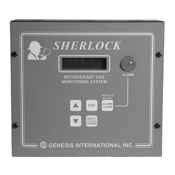
Allows the user to test the relays on or off. A method to check the wiring connections between relay outputs and their alarming devces. SHERLOCK ALARM REFRIGERANT GAS MONITORING SYSTEM PRESS TO SILENCE ALARM EXIT CLEAR SELECT CHANGE GENESIS INTERNATIONAL INC. 44-00-0297 SHERLOCK102/202 REV. 4.1 05-02-15... -
Page 26: Default Screen/ Response To Alarm
DEFAULT SCREEN / ALARM RESPONSES DEFAULT SCREEN The display is a 2 rows by 20 characters backlighted liquid crystal display. When the Control Module is first powered up, the unit will display its initialization screens. Thereafter, the reading and the setpoints of each enabled sensor are shown in alterating fash- ion every three seconds. -
Page 27: Access Menu
ACCESS MENU PLACE CONTROL INTO THE "VIEW ONLY MODE", <ACCESS MENU> "IN CHANGE MODE" or "ALL ACCESS MODE". VIEW ONLY MODE allows user accessing Menus and Sub-menus, no control parameters can be changed. CHANGE MODE allows control parameters to be changed except parameters in the System Config Menu. -
Page 28: Status Menu
STATUS MENU This menu allows the user to veiw but not change the various <STATUS MENU> controller parameters. Screen entries in “<STATUS MENU>” will only be shown if their respective control options are installed in the “<SYSTEM CONFIG MENU>” SELECT/ CHANGE At DEFAULT SCREEN, press UP/DOWN button to scroll to the "<STATUS MENU>". -
Page 29: Status Menu
STATUS MENU This is the active state of the alarm relays. <STS> SYSTEM ALM RLY:NORMAL-OPEN The optional zone alarm relays can be set for level 1&2 or just <ST>ZONE ALM RLY for level 2 ACTIVE BY LVL 1&2 The zone alarms can be made silenceable or unsilenceable <ST>ZONE ALM RLY :SILENCEABLE The alarms can automatically clear or stay on and be manually... -
Page 30: Alarm Log Menu
ALARM LOG MENU This menu also shows the most recent 10 alarm logs. <ALARM LOG M> At DEFAULT SCREEN, press UP/DOWN arrow button to scroll to the "<ALARM MENU>". Press the SELECT button to enter this menu. Each successive screen will show the last 10 alarms in reverse <ALMX>... -
Page 31: Setpoint Menu
SETPOINT MENU These Sub-menus are to be followed if the setpoints and alarm <SETPOINT MENU> delays for one or all of the control system are to be changed Prior to changing the control setpoints, ensure that the control system is in the "IN CHANGE MODE" or "ALL ACCESS SELECT/ MODE". -
Page 32: Setpoint Menu
SETPOINT MENU (THE SETBACK ENTRIES WILL NOT BE SHOWN IF SENSOR SETBACK OPTION WAS NOT INSTALLED.) When the Control is in SETBACK MODE, the Setback Set- point and Delay is used as the alarming critera. The Setback Setpoint and Delay are usually set to a higher value. This prevents fault alarming in some applications. -
Page 33: Calibration Menu
CALIBRATION MENU This page and the next contain a brief overview of the "<CALI- <CALIBRATION MENU> BRATION MENU>" of the Sherlock Control System. The pages after these two contain specific instruction on calibrating the Sherlock Monitoring System and its sensors. SELECT/ CHANGE The CALIBRATION MENU contains three basic functions:... -
Page 34: System Config Menu
SYSTEM CONFIG MENU CONFIGURE THE CONTROL IN THE <SYSTEM CONFIG MENU> <SYSTEM CONFIG MENU> At DEFAULT SCREEN, press UP/DOWN arrow buttons until the <SYSTEM CONFIG MENU> screen appears. Press SELECT button to enter the "SYSTEM CONFIG MENU" It is recommended that before the Sherlock Control Module is initially programmed, the memory should be cleared. -
Page 35: System Config Menu
SYSTEM CONFIG MENU Press the DOWN arrow button to move to next entry. To set the Setback begin time, press SELECT button. The time <CFG>SETBACK SCH SELECT/ will begin to blink. Press the UP/DOWN arrow buttons to the ON TIME 12:00 CHANGE desired time. - Page 36 SYSTEM CONFIG MENU Press DOWN arrow button to move to the next option. Set <C>ALRM AUTO CLR the Latch Action for all relays The alarm relays can be set to SELECT/ AFTER NORMAL:YES "NO" (Alarms stay active until reset by a technician) or the CHANGE "YES"...
-
Page 37: Set Time Menu
SET TIME MENU The year, month, day and time can be viewed and changed <CLOCK MENU> here. At DEFAULT SCREEN, press UP/DOWN arrow buttons until the "<CLOCK MENU>" screen appears. Press SELECT button to "<CLOCK MENU>". SET THE TIME <CLK> HOUR:MIN Press SELECT button. -
Page 38: Test Menu
TEST MENU This menu is provided to facilitate wiring checks for each <TEST MENU> output. When entering into this menu. the relays retain their operating states. The relays can be turned ON (Energized) or OFF (De-Energized) by the user. The N.O. or N.C. settings on SELECT/ alarm relays have no effect on the test. -
Page 39: Zero Calibration
CALIBRATION Prior to shipment, all sensors manufactured by Genesis Interna- method is to adjust the zero offset on the sensor itself. More tional, Inc. are factory calibrated. The calibration method will complex method involving exposing the sensor to pre-measured set the base level (or Zero Level) and the gain (or Slope). As... -
Page 40: Measured Gas Calibration
CALIBRATION CALIBRATION KIT. The Calibration Kit contains the following items: Carrying Case Flow Regulating Valve Calibration Chamber 2.5 ft Vinyl Tubing Calibration Gas - Zero Level Calibration Gas - Span Gas. Flow Regulating Valve. The Flow Regulating Valve permits the sensor chamber or the IR Sensor chamber to be fi lled at a constant rate. -
Page 41: Measured Gas Calibration
CALIBRATION 4) Once the measured gas testing is complete and no gas is It is recommended that infrared sensors are zero calibrated present and the sensor is mounted in normal conditions, do every 6 months to insure accuracy. Most of the time push the push button calibration once again to remove any artifi... - Page 42 CALIBRATION Calibration - Sherlock Oxygen Sensor b. Wait 5 minutes. See manual 44-0165 Oxygen Sensor Calibration for more c. Open the valve again for 2 minutes. d. Wait 5 minutes. SENSOR WIRING TERMINAL 2) Follow these programming procedures.: Ensure that the control access in "IN CHANGE MODE" or "ALL ACCESS"...
-
Page 43: Trouble Shooting
Measured gas calibration testing should only be necessary for double checking accuracy and testing to see if the sensor is working properly. Genesis customer service. If it still reads full scale double check for proper wiring. How old is the sensor? Check start up date on the sensor cover. -
Page 44: Infrared Sensor Trouble Shooting
Check for wiring problems. Turn Dip Switch 5 to on. If the con- reading trol reads about 200 there could be a sensor problem and contact Genesis customer service. If it still reads full scale double check for proper wiring. How old is the sensor? Check start up date on the sensor cover. -
Page 45: Electro-Chemical Ammonia Sensor Trouble Shooting
If it is not written down and a problem due to calibration occurs, the Genesis technician may not be able to help and this could void the warranty. These sensors can last an average of 24 months before replacing the sensor element if the maintenance schedule is followed. -
Page 46: Glossary
GLOSSARY This is the "absolute value" for the sensor also "Hydro Flouro Carbon" This is a class of known as the "raw reading" for the sensor. refrigerants. ACGIH "American Conference of Governmental LVL 1(2) "Level 1(2)" Industrial Hygienists" This organization sets K1A, K1B, ETC. -
Page 47: Components Part List
Regulating Valve, Standard Calibration Kit 46-0003 Sherlock 102 Control NEMA 4X (SHER102-4) 60-0141 Regulating Valve, Ammonia Calibration Kit 46-0010 Sherlock 102 Control With Analog Output (SHER102-A) 82-0375 Calibration Kit For R-11 Sensors 88-0221 Sherlock 202 Control (SHER202) 82-0319 Calibration Kit For R-12 Sensors... -
Page 48: General Wiring Schematic
GENERAL WIRING SCHEMATIC - SHERLOCK SYSTEM SHERLOCK 102 AND 202 COMPLETE SYSTEM 4 GND 3 V+ 2 OUT- 1 OUT+ CONTACTOR COIL SNR A IN FOR EXHAUST FAN COMM- COMM+ STARTER IR SENSOR SNR B IN CMOS SENSOR SHUTDOWN CONTACTOR FOR... -
Page 49: Field Wiring Diagram (Blank)
PAGE FOR FIELD WIRING - SHERLOCK SYSTEM 44-00-0297 SHERLOCK102/202 REV. 4.1 05-02-15... -
Page 50: Recommended Alarm Setpoints
RECOMMENDED SETPOINTS Before using the table below of "Suggested Set- Alarm levels can also vary depending upon which points", it must be noted that different munici- refrigerant is used. If your refrigerant is not listed, palities use different standards depending upon check the manufacturers material safety data local laws. - Page 51 THIS PAGE INTENTIONALLY LEFT BLANK 44-00-0297 SHERLOCK102/202 REV. 4.1 05-02-15...
-
Page 52: Warranty Information
FOR WARRANTED ITEMS MAY ALSO APPLY. WITHIN 30 DAYS OF THE DATE OF SHIPPING GENESIS WILL TAKE BACK ANY UNUSED EQUIPMENT AND REFUND THE CUSTOMER IN FULL MINUS A 15% RESTOCKING FEE AND ANY DAMAGE CHARGES OR TESTING CHARGES. IF THE UNIT IS RETURNED WITHIN 90 DAYS AN IN HOUSE CREDIT WILL BE GIVEN MINUS A 15% RESTOCKING FEE.
Need help?
Do you have a question about the SHERLOCK 102 and is the answer not in the manual?
Questions and answers