Table of Contents
Advertisement
Multi-purpose
Thruline
Wattmeter
®
Rf Power Analyst
®
Model 4391A
Cable And Antenna Tester
For Wireless Systems
Operation Manual
©Copyright 2016 by Bird Technologies, Inc.
Instruction Book Part Number 920-4391A Rev. K
Thruline® and Power Analyst® are Registered Trademark of
Bird Electronic Corporation
Advertisement
Table of Contents

Related Manuals for BIRD 4391A


Summary of Contents for BIRD 4391A
- Page 1 ® Rf Power Analyst ® Model 4391A Cable And Antenna Tester For Wireless Systems Operation Manual ©Copyright 2016 by Bird Technologies, Inc. Instruction Book Part Number 920-4391A Rev. K Thruline® and Power Analyst® are Registered Trademark of Bird Electronic Corporation...
-
Page 2: Safety Precautions
Safety Precautions The following are general safety precautions that are not necessarily related to any specific part or procedure, and do not necessarily appear elsewhere in this publication. These precautions must be thoroughly understood and apply to all phases of operation and maintenance. WARNING Keep Away From Live Circuits Operating Personnel must at all times observe general safety precautions. -
Page 3: Safety Symbols
Safety Precautions Safety Symbols WARNING Warning notes call attention to a procedure, which if not correctly performed, could result in personal injury. CAUTION Caution notes call attention to a procedure, which if not correctly performed, could result in damage to the instrument. The caution symbol appears on the equipment indicating there is important information in the instruction manual regarding that particular area... -
Page 4: Warning Statements
Multi-Purpose Thruline Wattmeter RF Power Analyst Warning Statements The following safety warnings appear in the text where there is danger to operating and maintenance personnel, and are repeated here for emphasis. WARNING Use only Nickel Metal Hydride (NiMH) batteries that have a minimum capacity of 4500 milliampere hours (mAh). -
Page 5: Caution Statements
On page 6. CAUTION Never apply RF power to the Model 4391A Wattmeter unless both line section sockets are filled with either an element or a dust plug. If an element is used it is advisable to place the element with the arrow at a 90° angle to the coaxial line. - Page 6 Multi-Purpose Thruline Wattmeter RF Power Analyst CAUTION This instrument contains static sensitive electronic components. Before opening or servicing the unit, make sure that you understand and practice electrostatic discharge component handling. Failure to comply may result in permanent damage to sensitive components. On page 21.
- Page 7 Safety Precautions SERVICE SERVICING INSTRUCTIONS ARE FOR USE BY SERVICE - TRAINED PERSONNEL ONLY. TO AVOID DANGEROUS ELECTRIC SHOCK, DO NOT PERFORM ANY SERVICING UNLESS QUALIFIED TO DO SO. SERVICIO LAS INSTRUCCIONES DE SERVICIO SON PARA USO EXCLUSIVO DEL PERSONAL DE SERVICIO CAPACITADO. PARA EVITAR EL PELIGRO DE DESCARGAS ELÉCTRICAS, NO REALICE NINGÚN SERVICIO A MENOS QUE ESTÉ...
- Page 8 Multi-Purpose Thruline Wattmeter RF Power Analyst UNITS ARE EQUIPPED WITH RECHAREABLE BATTERIES. THESE ARE TO BE REPLACED BY AUTHORIZED SERVICE PERSONNEL ONLY!!! LAS UNIDADES VIENEN EQUIPADAS CON BATERIAS RECARGABLES. ¡¡¡Y SOLAMENTE EL PERSONAL DE SERVICIO AUTORIZADO PUEDE REEMPLAZARLAS!!! GERÄTE SIND MIT WIEDER AUFLADBAREN BATTERIEN BESTÜCKT.
- Page 9 Safety Precautions USE CORRECT VOLTAGE SETTING AND FUSE - SEE MANUAL. UTILISER UNE TENSION ET UN FUSIBLE CORRECTS - CONSULTER LE MODE D'EMPLOI. USE LA INSTALACION Y FUSIBLE DE VOLTAJE CORRECTO - VEA EL MANUAL. AUSSCHLIESSLICH VORSCHRIFTSMÄSSIGE WECHSELSPANNUNGS-EINSTELLUNG UND SICHERUNG BENUTZEN - SIEHE DAZU HANDBUCH.
- Page 10 Multi-Purpose Thruline Wattmeter RF Power Analyst RF VOLTAGE MAY BE PRESENT IN RF ELEMENT SOCKET - KEEP ELEMENT IN SOCKET DURING OPERATION. DE LA TENSION H.F. PEAT ÊTRE PRÉSENTE DANS LA PRISE DE L'ÉLÉMENT H.F. - CONSERVER L'ÉLÉMENT DANS LA PRISE LORS DE L'EMPLOI.
-
Page 11: About This Manual
About This Manual This manual covers the operating and maintenance instructions for the following models: 4391A Changes to this Manual We have made every effort to ensure this manual is accurate. If you discover any errors, or if you have suggestions for improving this manual, please send your comments to our Solon, Ohio factory. -
Page 12: Table Of Contents
Table of Contents Safety Precautions ......... i Safety Symbols . - Page 13 Table of Contents Chapter 5 Maintenance ........16 Preventive Maintenance .
-
Page 14: Chapter 1 Introduction
Because of its complexity, the proper use of the 4391A is not always obvious. For this reason it is strongly advised that this manual be read in its entirety before using the device. -
Page 15: Description
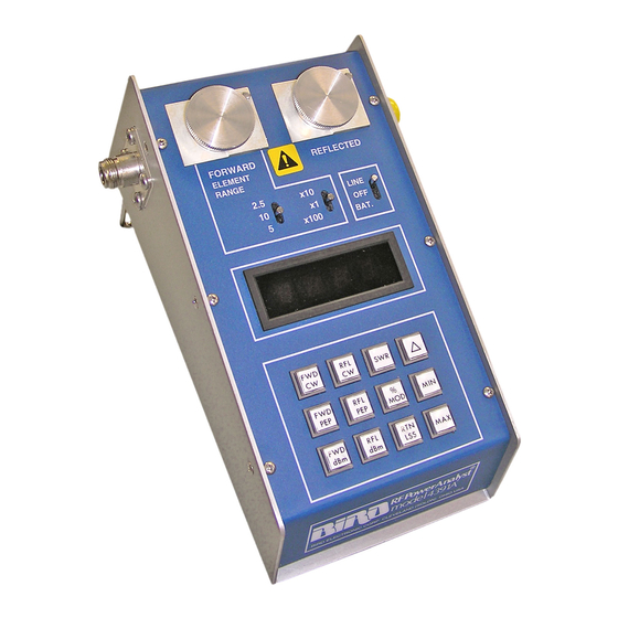
9-5/8 inches deep by 6-1/4 inches wide (111 mm x 244 mm x 159 mm) including connections, see . At each end of the line section are Bird Figure 1 Quick-Change type RF connectors which may be easily interchanged with any other Bird QC connector. -
Page 16: Chapter 2 Theory Of Operation
Chapter 2 Theory of Operation Description of Operation is a block diagram of the major functional parts of the Model 4391A RF Figure 2 Wattmeter. The Microcomputer integrated circuit shown, controls all the other portions of the instrument, which fall into two major groups. -
Page 17: Elements, Analog Circuitry, And A/D Converter
Theory of Operation Elements, Analog Circuitry, and A/D Converter These components are controlled by the computer. The Plug-in Elements in the line section provide low level positive voltages related to the instantaneous value of power (see ). The first group of solid state switches selects the Figure 3 forward element, the reflected element, or ground as the input to the preamplifier which boosts these signals to 0.1 to 2.0 volt range. - Page 18 Multi-Purpose Thruline Wattmeter RF Power Analyst stationary, the coupling currents produced from the waves of one direction will add in phase, and those produced from waves of the opposite direction will accordingly subtract in phase. The additive or “arrow” direction is assigned to the forward wave.
-
Page 19: Chapter 3 Installation
Chapter 3 Installation The Model 4391A RF Power Analyst is completely portable and very suitable for field or laboratory use. Its power is derived from rechargeable nickel metal hydride batteries inside the unit or from an AC outlet via the power cord supplied with the device. -
Page 20: Connections
Once the Model 4391A is installed in the coaxial line, a Plug-in Element or a pair of Plug-in Elements must be selected which correspond to the frequency and power levels to be measured. -
Page 21: Chapter 4 Operating Instructions
Operating Instructions Operating Modes The Model 4391A has nine modes of operation which are selected by pressing the mode keys momentarily. In addition, each mode has three output options selected by pressing the modifier keys. Detailed descriptions of the modes and output options follow. -
Page 22: Reading Reflected Cw Power
Multi-Purpose Thruline Wattmeter RF Power Analyst The Model 4391A arrives at values of CW power by a method quite different from analog meters such as the Model 43, also manufactured by Bird Electronic. While the two instruments will agree when the measured wave is of constant amplitude, AM or SSB waves will result in different indications (in the CW mode). -
Page 23: Measuring Peak Envelope Power
Operating Instructions Table 2 - Voltage Standing Wave Ratio (VSWR) Return Loss Reflected Return Reflected VSWR VSWR (dB) Power % Loss (dB) Power % 1.01 46.1 0.00 1.45 14.7 3.37 1.02 40.1 0.01 1.50 14.0 4.00 1.03 36.6 0.02 1.75 11.3 7.44 1.04... -
Page 24: Measuring Amplitude Modulation
Multi-Purpose Thruline Wattmeter RF Power Analyst Measuring Amplitude Modulation Only a forward element is required for this mode. Point the element in the direction of forward power and press % MOD. Modulation is displayed directly in percent, provided the average signal is above 10% and the PEP of the signal is below 400% of the element’s nominal full scale. -
Page 25: Measuring Power In Dbm
Operating Instructions Measuring Power in dBm Operation of the forward and reflected dBm modes is identical to the forward and reflected CW power modes, except that the resulting reading is converted to dB above 1 milliwatt before it is displayed. It should be noted that in doing this conversion, the range set on the slide switches is assumed to be watts rather than kilowatts or milliwatts. -
Page 26: Insertion Loss Or Attenuation
(P/N 4230-006-1), a DC feed-in adapter (P/N 4381-050), and a DC cable (P/N 3170-058-6). The Model 4391A is inserted at the source end of the device being measured. The second line section is inserted at the load end and its DC output is routed by the DC cable to the adapter inserted in the REFLECTED socket of the Model 4391A. -
Page 27: Using The Peaking Aid
Using the Peaking Aid The peaking aid is useful for making adjustments to optimize any of the parameters which the Model 4391A measures. After the mode is selected, press the delta () key momentarily. This blanks the least significant digit of the display, and replaces it with a right-facing arrow head if the measured quantity is increasing or a left-facing arrow head if it is decreasing. -
Page 28: Battery Care
Multi-Purpose Thruline Wattmeter RF Power Analyst Battery Care With average use, the nickel metal hydride batteries in the 4391A will power the unit for 12 hours before needing recharged. The 4391A will maintain rated accuracy until all the decimal points light, indicating that recharging is required. To recharge, connect AC power to the unit. -
Page 29: Chapter 5 Maintenance
Chapter 5 Maintenance The 4391A RF Power Analyst was designed and built to provide many years of trouble free service. This section provides the information needed to prevent and correct equipment failure. Preventive Maintenance To avoid unnecessary damage, always observe the following cautions:... -
Page 30: Long-Term Storage
RF Power Analyst. Table 6 Table 6 - Required Calibration Equipment Equipment Recommended Model Calibrator/Source Keithly Model 263 or equivalent Cable Assembly BNC to BNC (1 meter long) (1 Required) DC Feed-in Element Bird Electronic 4381-050 (1 required) -
Page 31: Initial Setup
Maintenance Initial Setup Note: On a clean flat workspace perform the following setup pro- cedure: 1. Remove the front panel. Refer to "Front Panel Removal" on page 21 2. Insert a DC feed-in adapter into the FWD element of the socket. 3. -
Page 32: Element Wiper Contact Adjustment
Multi-Purpose Thruline Wattmeter RF Power Analyst Element Wiper Contact Adjustment CAUTION If the element cannot be fully inserted into the socket, do not force it. You might damage the element. CAUTION Be careful not to bend the spring out so far that it interferes with insertion of the elements. -
Page 33: Troubleshooting
Maintenance Troubleshooting General The troubleshooting instructions are intended to aid in fault isolation. This is accomplished through the use of a troubleshooting table. First, locate the symptom(s) in the problem column of . In some cases Table 7 the same fault can have more than one symptom and more than one possible remedy. -
Page 34: Disassembly
Multi-Purpose Thruline Wattmeter RF Power Analyst PROBLEM POSSIBLE CAUSE REMEDY One segment of Defective Display Replace the display. a display does not light Low charge on the batteries Recharge the batteries. All decimal Replace the Main circuit board points stay lit Defective circuit component assembly. -
Page 35: Main Printed Circuit (Pc) Board Removal
Maintenance 5. Lift the front panel from the housing. Note: Be careful to clear the line section blocks. 6. Remove pads from the three toggle switches. Figure 18 Removing Front Panel Main Printed Circuit (PC) Board Removal 1. Remove the front panel. Refer to "Front Panel Removal"... -
Page 36: Qc Connectors Removal
Multi-Purpose Thruline Wattmeter RF Power Analyst Figure 19 Removing Main PCB QC Connectors Removal 1. Remove the eight screws (four on each connector) that secure the connectors to the housing ( , item 1). Figure 20 2. Remove the two “QC” connectors (item 2) by pulling them away from the line section assembly. - Page 37 Maintenance Figure 20 Removing QC Connectors and Line Section CAUTION This instrument contains static sensitive electronic components. Before opening or servicing the unit, make sure that you understand and practice electrostatic discharge component handling. Failure to comply may result in permanent damage to sensitive components.
-
Page 38: Battery Replacement
Multi-Purpose Thruline Wattmeter RF Power Analyst Figure 21 Removing Line Section PCB Battery Replacement 1. Remove the front panel (refer to "Front Panel Removal" on page 21 2. Remove the four screws and lock washers ( , item 1) that secure Figure 22 the Main PCB. - Page 39 Maintenance Note: The polarity orientation of the batteries must remain consistent. 6. Remove the three battery tubes from the battery clips then remove two batteries from each tube. Install new batteries into the tubes then secure the tubes in the battery clips. Note: Be sure to observe proper polarity.
-
Page 40: Parts List
Multi-Purpose Thruline Wattmeter RF Power Analyst Parts List This section contains an illustrated list of all authorized replacement parts for the 4391A RF power Analyst. Parts are grouped into major assemblies and sub- assemblies. Figure 24 Parts Drawing Item No. - Page 41 Maintenance Figure 25 Line Section Assembly (S/N 1723 & below) Item No. Description Part No. Figure 25 Line Section, Subassembly 4381-005 PC Board, Data Acquisition Assy 4391A006 Bead, Keying 4391-026 Spacer 4391-027 Screw, Machine, filister head, COML No. 4-40, 1/4 in. lg, sst Support 4381-029 Screw, Machine, filister head,...
- Page 42 Multi-Purpose Thruline Wattmeter RF Power Analyst Figure 26 Line Section Assembly (S/N 1724 & above) Part No. Description Part No. Figure 26 Line Section, Subassembly 4381-005 PC Board, Data Acquisition Assy 4391A006 Bead, Keying 4391-026 Spacer 4391-027 Screw, Machine, filister head, COML No.
-
Page 43: Customer Service
If the unit needs to be returned for any reason, request an Return Material Authorization (RMA) through the Bird Technologies website. All instruments returned must be shipped prepaid and to the attention of the RMA number. -
Page 44: Specifications
RF Transmission in 50 ohm lines Medium † RF Power Range 100 mW to 10 kW full scale using Bird Plug-in Elements. Accuracy not guaranteed with components not supplied by Bird Usable Over- To 120% of scale on CW, PEP, SWR, and Return loss Range functions. - Page 45 Maintenance † Frequency band and power range is determined by the Plug-in Elements selected. See Bird Catalog for availability. Some modes require two elements in a 10:1 power ratio. †† VSWR and return loss functions settle in less than 1 second.
-
Page 46: Limited Warranty
Limited Warranty All products manufactured by Seller are warranted to be free from defects in material and workmanship for a period of one (1) year, unless otherwise specified, from date of shipment and to conform to applicable specifications, drawings, blueprints and/or samples. Seller’s sole obligation under these warranties shall be to issue credit, repair or replace any item or part thereof which is proved to be other than as warranted;...
Need help?
Do you have a question about the 4391A and is the answer not in the manual?
Questions and answers