Table of Contents
Advertisement
Quick Links
Advertisement
Table of Contents

Related Manuals for LI-COR LI-3100C


Summary of Contents for LI-COR LI-3100C
- Page 1 LI-3100C Area Meter Instruction Manual ®...
- Page 2 LI-3100C Area Meter Instruction Manual Publication No. 984-07704 June, 2004 LI-COR 4421 Superior St. P.O. Box 4425 Lincoln, NE 68504 USA Telephone: (402) 467-3576 FAX: 402-467-2819 Toll-free 1-800-447-3576 (U.S. & Canada) envsales@licor.com www.licor.com © Copyright 2004. LI-COR, inc.
-
Page 3: Declaration Of Conformity
Lincoln, Nebraska 68504 USA Phone: 402-467-3576 FAX: 402-467-2819 Toll-free: 1-800-447-3576 (U.S. & Canada) E-mail: envsales@licor.com Declaration of Conformity Manufacturer’s Name: LI-COR Inc. Manufacturer’s Address: 4421 Superior Street Lincoln, Nebraska USA 68504 declares that the product Product Name: Area Meter Model Number(s): LI-3100C... - Page 4 The information contained in this document is subject to change without notice. LI-COR makes no warranty of any kind with regard to this material, including, but not limited to the implied warranties of merchantability and fitness for a particular purpose. LI-COR shall not be liable for errors contained herein or for incidental or consequential damages in connection with the furnishing, performance, or use of this material.
-
Page 5: Table Of Contents
Table of Contents Section 1. General Information 1.1 Instrument Function ............1.2 Operational Features ............Section 2. Pre-operation 2.1 Rear Housing Removal ............2.2 Transparent Belt Tension Adjustment ........2.3 Fluorescent Tube Installation ..........2.4 Camera Installation .............. 2.5 Voltage Selector Operation and Characteristics ....Section 3. - Page 6 6.2 Removal Procedure ............. Section 7. Using the Windows Interface Software 7.1 Installing the PC Interface Software ........7.2 Connecting the LI-3100C to a Computer......7.3 Software Basics..............7-11 7.4 Creating a Log File............... 7-12 7.5 Missed Data Packets ............7-15 7.6 Importing a Data File to a Spreadsheet ........
-
Page 7: Section 1. General Information
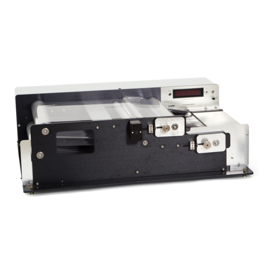
General Information 1.1 Instrument Function The LI-3100C Area Meter is designed for biological, industrial, and other applications requiring rapid, precise area (length or width) measurements. Samples are placed between the guides on the lower transparent belt and allowed to pass through the instrument. As items... -
Page 8: Operational Features
General Information 1.2 Operational Features The LI-3100C features interchangeable 1.0 mm and 0.1 mm resolution capability that is furnished with a single 28 mm camera lens. A 25 cm wide sample guide is provided for both 1.0 mm 0.1 mm resolution configurations. -
Page 9: Section 2. Pre-Operation
Pre-operation The following procedures must be performed before using the LI-3100C for the first time: Tighten the transparent belts Install the 15 watt fluorescent tube Install the camera lens Set the voltage selector at the proper position and check to see if the correct fuse is installed Each of these procedures is discussed below. -
Page 10: Fluorescent Tube Installation
Preoperation Procedure holding tension on the bearing block with the remaining fingers of the same hand. Fine adjustments are performed by twisting the block adjustment screw to push the sliding bearing block. The knurled knobs located on the pulley bearing blocks must be loosened to allow block movement. Figure 1. - Page 11 Preoperation Procedure Figure 2. Area Meter in 0.1 mm resolution configuration. (A) front sliding bearing blocks, (B) "Lamp Start" switch, (C) "Zero" button, (D) sample guides, (E) screws to be removed in order to detach the front panel. Slide the tube into the exposed hole in the instrument rear plate. Rotate the tube as needed until it seats in the front connector.
-
Page 12: Camera Installation
Preoperation Procedure Recessed mounting screws; use hex key to remove Figure 3. Area meter with fluorescent tube connector housing removed. (A) fluorescent tube connector housing. (B) fluorescent tube with exposed pins. 2.4 Camera Installation Unpack the camera. Do not remove the black light shield tape adjoining the camera circuit board. -
Page 13: Voltage Selector Operation And Characteristics
Preoperation Procedure 2.5 Voltage Selector Operation and Characteristics The voltage selector is located in the power connector module (Figure 1). The selector is inspected for proper voltage by sliding the clear plastic window to a position over the power connector. The visible number on the small printed circuit board located under the fuse indicates the selected voltage as follows: either 100 or 120 V for 105-126 VAC operation... -
Page 14: Section 3. Operation
Operation 3.1 Instrument Activation After reading and performing the procedures in Section 2, the following steps should be taken to activate the instrument: Connect the supplied power cord to the power input connector at the rear of the instrument. A grounded three prong wall connector is required for electrical service. -
Page 15: Belt Tension And Tracking Adjustment
Operation 3.3 Belt Tension and Tracking Adjustment Belt tracking is adjusted by moving the sliding pulley bearing blocks (Figures 1 and 2). The belts likely will not maintain alignment without some adjustment. If a belt progresses toward one end of a pulley, then tighten that side of the belt. -
Page 16: Calibration Procedure
Operation opposite effect. In addition, incorrect calibration resulted in larger errors with these samples. The LI-3100C now uses the entire 25 cm measurement width for high resolution (0.1 mm ) mode, so it is important to compensate for the above-mentioned edge effect for the calibration procedure. While... -
Page 17: Pressing Roller Adjustment
Operation sample width area. For example, use 5 zones from front to back, and repeat to total 10 readings. If the error exceeds 2%, carefully turn the CAL screw a small amount, clockwise to increase, or counterclockwise to decrease. Avoid changing the adjustment too much. - Page 18 Operation Figure 4. Adjustable press roller in the retracted position.
- Page 19 Operation Figure 5. Press roller in position for use with thin leaves.
-
Page 20: Section 4. Changing Measurement Resolution
Changing Measurement Resolution 4.1 Choosing Measurement Resolution The LI-3100C utilizes the full measurement width at all times, for both 0.1 and 1.0 mm resolution. The 0.1 mm resolution may be preferable , since it provides the best accuracy, particularly with small or complex shaped objects to 0.5 mm in width. -
Page 21: Changing From 0.1 Mm To 1.0 Mm Resolution
Changing Resolution Figure 6. LI-3100C camera position configured for 0.1 mm operation. Lightly tighten the set screws. Be sure that the lens cover has been removed and that no other obstruction is in the optical path. Replace the rear housing. - Page 22 Changing Resolution Figure 7. LI-3100C camera position configured for 1.0 mm operation. Align the yellow focus mark to the red lens index mark. Lightly tighten the set screws. Be sure the lens cover has been removed and that no other obstruction is in the optical path.
-
Page 23: Section 5. Maintenance
Maintenance 5.1 Changing the Fluorescent Tube Grasp the tube near each end by the edges of the upper transparent belt. Twist the tube 1/4 revolution to loosen it in the connectors. Remove the rear tube connector by loosening the two recessed mounting screws (Figure 3). - Page 24 (Figure 8). Figure 8. LI-3100C with front plate removed. (A) Fluorescent tube power connector, (B) pulley support brackets, (C) upper belt rocking idler, (D) lower belt idler, (E) proper location of pulley peripheral end grooves, lower belt idler peripheral end groove, and the end plate notch.
- Page 25 Maintenance Draw the upper belt rocking idler and the lower idler outward to remove them. Slide the belts outward to remove them (Figure 9). Figure 9. Upper belt rocking idler and lower belt idler removed. To remove the belts, draw them outward. Caution: Do not exert excessive upward pressure on the drive pulleys as the belts are removed.
-
Page 26: Cleaning The Transparent Belts
Maintenance After the belts are placed over the drive pulleys, slide the upper and lower pulleys through the belts and insert the pulley shaft into the rear plate bearing. Be sure that the peripheral end groove is toward the front and that it rests in the pulley support bracket (Figures 7 and 5.2.3 Replacing the Transparent Belts Slide the lower belt onto the pulleys. -
Page 27: Cleaning The Mirror Or Camera Lens
Maintenance facilitated by momentarily activating the "ON/OFF" switch to rotate the belt so that you can clean the portion of the belt that is near the sample tray. The inner surfaces are cleaned by reaching into the access ports in the front plate. Loosen the belts to facilitate cleaning the pulley surfaces. -
Page 28: Cleaning The Motor And Belt Drive System
Maintenance 5.6 Cleaning the Motor and Belt Drive System The motor and belt drive system requires no routine service or lubrication. If excessive debris becomes embedded into the belt, it can be removed with a small stiff brush. -
Page 29: Section 6. Removing The Upper Belt Assembly
Removing the Upper Belt Assembly 6.1 Purpose Some sampling requirements are better served by single belt operation. Under some conditions, the upper belt pressure may damage samples, or the upper belt rocking idler may cause undesirable mechanical pressure. Removing the upper belt pulley, drive pulley, and rocking idler will provide a more obstruction-free path through the sensitive area. - Page 30 Removing the Upper Belt Assy. visible on the front of the instrument which fasten the pulley support brackets (Figure 8). Do not loosen those screws. Remove the front plate slowly. Be certain that all pulleys and idlers remain in place, resting on the support brackets (Figure 8). This is accomplished by repeatedly pressing the pulleys and idlers back into their rear plate bearings.
-
Page 31: Section 7. Using The Windows Interface Software
Windows Interface Software The 3100-500 Windows Interface software allows the use of a computer to monitor and record data generated by the LI-3100C. The 3100-500 software features: Display of individual area, leaf length, average width, and maximum width. Indicator for resolution setting on LI-3100C. -
Page 32: Connecting The Li-3100C To A Computer
If you want to interface to a computer with a 25-pin serial port, a 9-pin to 25-pin adapter must be used. Turn on the LI-3100C. Start the lamp by pressing and holding the lamp button for a few seconds and then releasing. -
Page 33: Usb Connection
Connect the other end of the cable to the PC's USB port. Turn on the LI-3100C. Start the lamp by pressing and holding the lamp button for a few seconds and then releasing. - Page 34 Using the Windows Interface Software Figure 12. Specify location of driver. 3. When the warning window appears (Figure 13), click Continue Anyway. Figure 13. Compatibility warning window.
- Page 35 4. Click Finish to close the wizard (Figure 14). Figure 14. Completion of Hardware Wizard. 5. Click on the LI-3100C program icon to start the program. The LI-3100C main window appears. Select Connect from the Connection menu, or click on the connect icon in the toolbar beneath the Connection menu.
- Page 36 Using the Windows Interface Software Figure 15. Windows 2000 New Hardware Wizard. 2. Check "Search for a suitable driver for my device." Click Next. (Figure 16). Figure 16. Search for driver.
- Page 37 Using the Windows Interface Software 3. Check "Specify a location" (Figure 17). Figure 17. Specify location of driver. 4. Enter the path or browse to the Drivers folder on the 3100-500 CD. (Figure 18). Figure 18. Enter path or browse CD. 5.
- Page 38 Using the Windows Interface Software Figure 19. Driver search results. 6. Click Finish to close the wizard (Figure 20). Figure 20. Completion of Hardware Wizard.
- Page 39 Using the Windows Interface Software 7. Click on the LI-3100C program icon to start the program. The LI-3100C main window appears. Select Connect from the Connection menu, or click on the connect icon in the toolbar beneath the Connection menu. A connection dialog box will appear.
- Page 40 Using the Windows Interface Software Figure 22. Search for driver. 3. Enter the path or browse to the Drivers folder on the 3100-500 CD. (Figure 23). Figure 23. Specify location of driver. 7-10...
-
Page 41: Software Basics
4. Click Finish to close the wizard (Figure 24). Figure 24. Completion of Hardware Wizard. 5. Click on the LI-3100C program icon to start the program. The LI-3100C main window appears. Select Connect from the Connection menu, or click on the connect icon in the toolbar beneath the Connection menu. -
Page 42: Creating A Log File
Using the Windows Interface Software software does not reset the counter on the LI-3100C. However, resetting the LI-3100C counter on the front instrument panel does reset the software counter. Figure 25. LI-3100C software, main window. To disconnect the PC software from the LI-3100C, choose Disconnect from the Connection menu. - Page 43 Using the Windows Interface Software Figure 26. New Data File dialog box. The main window of the LI-3100C program contains a grid where a log file can be viewed as it is being created. Pressing the Log Data button will prompt the user for remarks (if enabled) and append a new row of data to the log file.
- Page 44 "n" area observations, selectable by the user in the New Data File dialog box. Figure 28. Grid on main window of the LI-3100C software, populated by data logged to an open log file. To close the log file, select Close data file from the File menu, or click on the Close Data File icon in the toolbar beneath the File menu.
-
Page 45: Missed Data Packets
The data file can be imported into a spreadsheet such as Microsoft Excel by using the Text Import Wizard. Excel will open a wizard dialog box when the LI-3100C data file is opened. The wizard prompts the user for information about the text file being opened. Be sure to indicate that the file is Tab Delimited, as shown in Figure 30. - Page 46 Using the Windows Interface Software Figure 30. Microsoft Excel Text Import Wizard used to open LI-3100C data file. Figure 31. Example LI-3100C data file after being imported into a spreadsheet. 7-16...
-
Page 47: Using The Li-3000A Readout
Using the Windows Interface Software 7.7 Using the LI-3000A Readout The LI-3100C serial port can be converted to connect to the readout console of the LI-3000A Portable Area Meter for those users who desire this functionality (standard on earlier versions of the LI-3100). A gender-changing (male-female) straight-thru cable (not a null modem cable) connects the LI-3100C and 3000A-01. -
Page 48: Section 8. Troubleshooting
Troubleshooting The sections below define several potential problems and lists several possible causes and their solutions. 8.1 Continuous Spurious Data Accumulation Lens cover has not been removed from the camera. Remove lens cover. Camera is at the wrong location. Check the actual camera position as described in Sections 4.1 and 4.2. -
Page 49: Belts Not Tracking Properly
Return to the original position. Perform calibration as described in Section 3.4. If counts continue at an unacceptable rate, contact LI-COR. 8.2 Belts not Tracking Properly If a transparent belt travels to one side of the pulley during operation, then the sliding pulley bearing blocks must be adjusted. -
Page 50: Miscellaneous Malfunction
Troubleshooting Portions of the sample protrude beyond the sensitive zone as defined by the sample guides. Be sure that samples remain within the sensitive zone. Static electricity may be causing movement of dry samples. Wipe the belts with a damp cloth. Enclose the samples in a transparent sheath. -
Page 51: Laboratory Conditions
In conditions of very high electrical noise on the AC Mains power circuit, or improper chassis grounding (the 3rd terminal of the power cord), the auxiliary computer display and the LI-3100C display may differ by a small amount, for less than the basic accuracy. -
Page 52: Specifications
Specifications Resolution 1 mm or 0.1 mm (user-selectable). Scanning Area Resolution: 1 mm × 1 mm. 1 mm Resolution: 0.300 mm L × 0.33 mm W. 0.1 mm Accuracy Sample Area Resolution 10 cm 3 cm 1 cm 0.3 cm 1 mm ±... -
Page 53: Warranty
5. No-charge repair parts may be sent at LI-COR, inc.'s sole discretion to the purchaser for installation by purchaser. 6. LI-COR, inc.'s liability is limited to repair or replace any part of the instrument without charge if LI-COR, inc.'s examination disclosed that part to have been defective in material or workmanship. - Page 54 The foregoing constitutes LI-COR, inc.'s sole obligation and liability with respect to damages resulting from the use or performance of the instrument and in no event shall LI-COR, inc. or its representatives be liable for damages beyond the price paid for the instrument, or for direct, incidental or consequential damages.
- Page 55 ®...
Need help?
Do you have a question about the LI-3100C and is the answer not in the manual?
Questions and answers