
Related Manuals for Dell Latitude 7285


Summary of Contents for Dell Latitude 7285
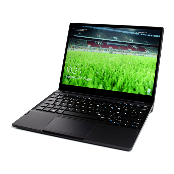
- Page 1 Latitude 7285 2-in-1 Owner's Manual Regulatory Model: T02J Regulatory Type: T02J001...
- Page 2 A WARNING indicates a potential for property damage, personal injury, or death. © 2017 Dell Inc. or its subsidiaries. All rights reserved. Dell, EMC, and other trademarks are trademarks of Dell Inc. or its subsidiaries. Other trademarks may be trademarks of their respective owners.
-
Page 3: Table Of Contents
Contents 1 System specifications............................ 6 Processor specifications..............................6 System specifications................................ 6 Memory specifications...............................7 Video specifications................................7 Audio specifications................................7 Port and connector specifications........................... 7 Communication specifications............................8 Camera specifications................................8 Display specifications.................................8 AC adapter specifications..............................9 Battery specifications................................ 9 Physical specifications..............................10 Active pen specifications..............................10 Wireless charging mat specifications.......................... - Page 4 Audio board..................................29 Removing the audio port............................29 Installing the audio port.............................30 Front facing camera.................................30 Removing the front camera .............................30 Installing the front camera............................31 Rear facing camera................................31 Removing the rear camera............................31 Installing the rear camera............................33 Coin cell battery................................33 Removing the coin cell battery..........................33 Installing the coin cell battery...........................
- Page 5 Key Features of Thunderbolt 3 over USB Type-C ....................51 Thunderbolt Icons..............................52 Dell Active Pen ................................53 Wireless charging mat..............................54 5 System setup.............................. 55 Entering BIOS without keyboard........................... 55 System setup options..............................55 General screen options..............................55 System Configuration screen options........................56 Video screen options..............................
-
Page 6: System Specifications
System specifications NOTE: Offerings may vary by region. The following specifications are only those required by law to ship with your computer. For more information about the configuration of your computer, go to Help and Support in your Windows operating system and select the option to view information about your computer. -
Page 7: Memory Specifications
Feature Specification Type Integrated on system board UMA controller Intel Integrated HD Graphics 615 External display Optional Dell Adapter - USB Type-C to HDMI/VGA/ Ethernet/USB 3.0/DisplayPort support NOTE: Supports VGA, DisplayPort, HDMI through the docking station. Audio specifications Feature Specification... -
Page 8: Communication Specifications
Wireless LAN Intel Dual-Band Wireless-AC 8265 Wi-Fi + BT 4.2 Wireless Card (2x2). Bluetooth Optional Mobile Broadband • Dell Wireless Qualcomm Snapdragon X7 LTE-A (DW5811e) for AT&T, Verizon, & Sprint (US) (Optional) • Dell Wireless Qualcomm Snapdragon X7 LTE-A (DW5811e) (EMEA/ROW) •... -
Page 9: Ac Adapter Specifications
Feature Specification Maximum viewing +/-80° angles—horizontal Maximum viewing +/-80° angles—vertical Pixel pitch 0.135 mm AC adapter specifications Feature Specification Type 45 W USB Type-C Input voltage 100 V AC–240 V AC Input current— 1.5 A maximum Input frequency 50 Hz to 60 Hz Output current 3.34 A (continuous) Rated output... -
Page 10: Physical Specifications
Feature Specification 34 Whr Long Life Cycle Battery (2- cell): Length 233.06 mm (9.170 inches) Width 90.73 mm (3.572 inches) Height 5.9 mm (0.232 inch) Weight 250.00 g (0.55 lb) Voltage 11.4 VDC Temperature range Operating • Charge: 0°C to 50°C (32°F to 122°F) •... -
Page 11: Wireless Charging Mat Specifications
Diameter —0.07 inch (1.8 mm) Wireless charging mat specifications Feature Specification Model Number PM30W17 PTU Rated Power 20W (AirFuel mode) 30W (Dell on Dell mode) Weight 645 g (Charging Mat only) Dimension: Legnth 12.28 inch (312.00 mm) Width 11.17 inch (283.82 mm) Height 0.69 inch (17.73 mm) -
Page 12: Using Your Tablet
Using your tablet This section covers how to power on and turn off your tablet including how to install the micro SD and micro SIM cards. Topics: • Turning off Your Tablet • Before Working Inside Your Tablet • After working inside your tablet Turning off Your Tablet Turning off your tablet completely shuts down your tablet. -
Page 13: Before Working Inside Your Tablet
Damage due to servicing that is not authorized by Dell is not covered by your warranty. Read and follow the safety instructions that came with the product. -
Page 14: After Working Inside Your Tablet
If the tablet is connected to a docking device (docked) such as the optional docking station or keyboard dock, un-dock it. Disconnect the power adapter from the tablet. Press and hold the power button for a few seconds to remove the flea power from the system board. CAUTION: To guard against electrical shock, always unplug your tablet from the electrical outlet. -
Page 15: Removing And Installing Components
Removing and Installing components This section provides detailed information on how to remove or install the components from your tablet. Topics: • microSIM card • microSD card • Display Panel • Battery • Power switch board • WLAN card • PCIe Solid State Drive (SSD) •... -
Page 16: Microsd Card
You can perform the same steps to remove the microSIM. microSD card Insert a paperclip or a microSD card removal tool into the pinhole on the microSD card tray [1]. Insert the microSD card into the slots indicated on the slot [2]. Align the cover with the groove on the tablet and slide it inside to secure the microSD [3]. -
Page 17: Display Panel
You can perform the same steps to remove the microSD. Display Panel Removing the display panel Follow the procedure in Before working inside your tablet. Remove the microSIM card microSD card. To release the display panel (with plastic scribe): Remove the M2x4 (4) screws that secure the display panel to the tablet [1]. b Use a plastic scribe to remove the microSIM/microSD cover [2]. - Page 18 Insert a plastic scribe into the microSIM/microSD slot. Pry the edges starting from microSIM/microSD slot [1, 2]. Removing and Installing components...
- Page 19 To release the display panel (with suction cup): Remove the M2x4 (4) screws that secure the display panel to the tablet [1]. b Attach a suction cup to the display panel above the left docking slot, located at the bottom of the system, while inserting a plastic scribe into the left docking slot to stabilize the system, and then carefully pull open the display panel using the suction cup.
- Page 20 Lift the display panel from the tablet. Slide the display panel [1], and flip the display panel [2]. Removing and Installing components...
- Page 21 CAUTION: Do not open the display panel more than 90 degrees as this may damage the display cable. Before removing display panel: Gently place the bottom edge of the display panel inside the bottom edge of the rear cover. b Flip open the display panel to a 180 degree angle and lay it flat on the surface. To disconnect the display cable: Remove the M1.6x2.5 (1) screw that secures the metal bracket on the system board [1].
- Page 22 Lift the metal tab from the system board [5]. Lift the tab and disconnect the display cable [6]. NOTE: Only disconnect the display cable from the system board. DO NOT disconnect the display cable from the display panel. Remove the display panel from the tablet. Removing and Installing components...
-
Page 23: Installing The Display Panel
Installing the display panel Place the display panel on a plane surface. Connect the display cable to the connector on the system boar NOTE: Make sure to insert the cable under the clips, if not, the system may not display video after reassembling. Place the metal bracket and replace the M1.6x2.5 (2) screws to secure the display panel. -
Page 24: Installing The Battery
NOTE: Once the battery cable is disconnected, practice caution not to damage the battery connector on the system board. The pins of the battery connector are extremely fragile, be careful not to bend the pins. NOTE: For defective system boards, technicians must always ensure that they attach the battery connector cap when re-packaging it for return. -
Page 25: Installing The Power Button Board
b Remove the M2x1.5 (2) screws that secure the power button board on the tablet [2]. Slide and remove the power button board from the tablet [3]. Installing the power button board Insert the power button board into the slot on the tablet. Replace the M2x1.5 (2) screws to secure the power button board to the tablet. -
Page 26: Installing The Wlan Card
Remove the M2x2.0 (1) screw securing the WLAN bracket [1]. b Lift the WLAN bracket away from the system board [2]. Disconnect the antenna cables from the WLAN card [3]. d Slide and lift the WLAN card from the connector on the system board 4]. Installing the WLAN card Insert the WLAN card into the connector on the system board. -
Page 27: Installing The Ssd Module
display panel battery To remove the SSD module: Remove the M2x2.0 (1) screw securing the SSD shield [1]. b Lift the SSD shield away from the tablet [2]. Slide and lift the SSD module from the slot on the tablet [3]. Installing the SSD module Insert the SSD module into the connector on the system board. -
Page 28: Wwan Card
WWAN card Removing the WWAN card Follow the procedure in Before working inside your tablet. Remove the: microSIM card microSD card display panel battery To remove the WWAN card: Remove the M2x2.0 (1) screw securing the WWAN bracket [1]. b Lift the WWAN bracket from the tablet [2]. Disconnect the antenna cables from the WWAN card [3]. -
Page 29: Audio Board
Replace the M2x2.0 (1) screw to secure WWAN bracket. Install the: battery display panel microSIM card microSD card Follow the procedure in After working inside your tablet. Audio board Removing the audio port Follow the procedure in Before working inside your tablet. -
Page 30: Installing The Audio Port
Installing the audio port Place and insert the audio port into the connector on the system board. Replace the M2X3 (2) screw to secure audio port on the system board. Affix the audio port on the system board. Connect the audio port cable to the connector. Install the: battery display panel... -
Page 31: Installing The Front Camera
Installing the front camera Insert the camera module into the slot on the tablet. Replace the M1.6x2.5 (2) screws to secure the front camera module. Connect the front camera cable to the system board.. Install the: battery display panel microSIM card microSD card Follow the procedure in After working inside your... - Page 32 microSIM card microSD card display panel battery To disconnect front camera cable: Lift the latch and disconnect the front camera cable [1]. b Remove the front camera cable from the system board [2]. To remove the rear camera: Disconnect the rear camera cable from the system board [1]. b Remove the M1.6x2.5 (1) screw securing the rear camera module [2].
-
Page 33: Installing The Rear Camera
Installing the rear camera Insert the rear camera module into the slot on the tablet. Replace the M1.6x2.5 (1) screw to secure the rear camera module. Connect the rear camera cable to the system board. Connect the front camera cable to the system board. Install the: battery display panel... -
Page 34: Installing The Coin Cell Battery
battery front facing camera To remove the coin cell battery: Disconnect the coin cell battery cable from the connector on the system board [1]. b Pry the coin cell battery to release from the adhesive and lift it away from the system board [2]. Installing the coin cell battery Place the coin cell battery into the slot on the system board. -
Page 35: Docking Board
Docking board Removing the docking board Follow the procedure in Before working inside your tablet. Remove the: microSIM card microSD card display panel battery To release the docking board: Disconnect the docking board cable from the system board [1]. b Remove the M1.6x4 (2) screws securing the docking board bracket to the docking board [2]. Remove the docking board bracket [3]. -
Page 36: Thunderbolt Over Type-C Usb Bracket
Replace the M1.6x4 (2) screws to secure the docking board to the tablet. Connect the docking board cable to the connector on the system board. Install the: battery display panel microSIM card microSD card Follow the procedure in After working inside your tablet. -
Page 37: Installing The Thunderbolt Over Type-C Usb Bracket
Installing the thunderbolt over Type-C USB bracket Insert the thunderbolt over Type-C USB bracket into the slot on the tablet. Replace the M2x2.0 (3) screws to secure the thunderbolt over Type-C USB bracket to the tablet. Install the: battery display panel microSIM card microSD card Follow the procedure in... - Page 38 To remove system board: Remove the M1.6x1.5 (4) screw that secures the system board to the tablet [1]. b Lift the system board from the tablet [2]. Removing and Installing components...
-
Page 39: Installing The System Board
Installing the system board Align the system board with the screw holders on the tablet. Replace the M1.6x1.5 (4) screws to secure the system board to the tablet. Connect the USH board cable, docking board cable, audio board cable, power button cable to the connectors on the system board. Install the: thunderbolt over Type-C USB bracket coin cell battery... -
Page 40: Installing The Speaker
To remove the speaker: Peel the speaker adhesive cable from the tablet [1]. b Lift the speaker from the tablet [2]. Installing the speaker Align the speaker with the holders on the tablet. Affix the speaker adhesive tape on the tablet. Removing and Installing components... -
Page 41: Back Cover
Route the WLAN cable through the retention clips on the tablet. Install the: system board thunderbolt over Type-C USB bracket coin cell battery rear camera front camera WWAN card SSD card WLAN card battery display panel microSIM card microSD card Follow the procedure in After working inside your tablet. - Page 42 Install the following component: system board thunderbolt over Type-C USB bracket docking board coin cell battery rear camera front camera audio port WWAN card SSD card WLAN card power button board battery display panel microSIM card microSD card Follow the procedure in After working inside your tablet.
-
Page 43: Technology And Components
Hard drive options • Drivers • Thunderbolt over Type-C • Dell Active Pen • Wireless charging mat Power adapter This system is shipped with 45 W Type-C power adapter. WARNING: When you disconnect the power adapter cable from the tablet, grasp the connector, not the cable itself, and then pull firmly but gently to avoid damaging the cable. -
Page 44: Chipset
Starting the camera To start the camera, open an application that uses the camera. For instance, if you tap the Dell webcam central software or the Skype software that is shipped with the 2-in-1, the camera turns on. Similarly, if you are chatting on the internet and the application requests to access the webcam, the webcam turns on. -
Page 45: Hard Drive Options
If the Camera App is not available in the apps list, search for it. Hard drive options This system supports M.2 SATA SSD, M.2 PCIe NVMe SSD, and M.2 PCIe NVMe SED. Technology and components... -
Page 46: Drivers
Drivers This section lists the drivers associated with the components shipped with your tablet. System drivers Figure 1. System drivers Technology and components... -
Page 47: Disk Driver
Disk driver Figure 2. Disk driver Technology and components... -
Page 48: Sound, Video And Game Controller Drivers
Sound, video and game controller drivers Figure 3. Sound, video, and game controllers Technology and components... -
Page 49: Storage Controller Drivers
Storage controller drivers Figure 4. Storage controllers Technology and components... -
Page 50: Network Drivers
Network drivers Figure 5. Network drivers Graphics driver Figure 6. Graphics driver Technology and components... -
Page 51: Thunderbolt Over Type-C
Thunderbolt over Type-C Thunderbolt is a hardware interface that combines data, video, audio, and power in a single connection. Thunderbolt combines PCI Express (PCIe) and DisplayPort (DP) into one serial signal, and additionally provides DC power, all in one cable. Thunderbolt 1 and Thunderbolt 2 use the same connector as miniDP (DisplayPort) to connect to peripherals, while Thunderbolt 3 uses a USB Type-C connector. -
Page 52: Thunderbolt Icons
Thunderbolt Icons Technology and components... -
Page 53: Dell Active Pen
Quick launch and note taking over lock screen (requires Bluetooth pairing) • LED light to show Bluetooth pairing status • 12 months battery life**, with AAAA battery *Need to install “Active Control Panel” from dell.com/support/drivers **Based on 3 hours daily usage for 5 days a week Technology and components... -
Page 54: Wireless Charging Mat
• Suitable for Category 5 AirFuel certified PRUs. • Dell-branded products carry a 1-year limited hardware warranty CAUTION: Do not insert any objects between the keyboard and the wireless charging mat or between the wireless charging mat and the table. Specifically, avoid CD/DVDs, RFID cards/devices, credit cards and other thin metal objects. These devices may be damaged if they are placed as stated above. -
Page 55: System Setup
Entering BIOS without keyboard Press the power button to turn on your tablet. Press and hold the Volume Up button when the Dell logo appears on the screen. When the F12 boot selection menu appears, select BIOS Setup using the Volume Up button. -
Page 56: System Configuration Screen Options
Option Description • Device Information: Displays M.2 PCIe SSD-0, M.2 PCIe SSD-1Passthrough MAC address, Video Controller, Video BIOS Version, Video Memory, Panel Type, Native Resolution, Audio Controller, Wi-Fi Device, WiGig Device, Cellular Device, Bluetooth Device Battery Information Displays the battery status health and whether the AC adapter is installed. Boot Sequence Boot sequence: Windows boot manager (selected by default) - Page 57 A USB Keyboard and/or mouse connected to the platforms USB ports will continue to function within BIOS Setup if this options is disabled. Dell Type-C Dock This field lets you always allow Dell docks. Configuration Always Allows Dell Docks (selected by default)
-
Page 58: Video Screen Options
Option Description • 5 sec • 10 sec (selected by default) • 15 sec • 30 sec • 1 min • 5 min • 15 min • Never Keyboard Backlight The Keyboard Backlight with AC option does not affect the main keyboard illumination feature. Keyboard with AC Illumination will continue to support the various illumination levels. - Page 59 Option Description Default Setting: Enable Strong Password is not selected. NOTE: If Strong Password is enabled, the Admin and System passwords must contain at least one uppercase character, one lowercase character and should be at least 8 characters long. Password Allows you to specify the minimum and maximum password lengths of the Administrator and System passwords.
-
Page 60: Secure Boot Screen Options
Option Description Admin Setup Allows you to prevent users from entering Setup when an Administrator password is set. Lockout Default Setting: This option is disabled. Master password This option is not enabled by default. lockout Secure Boot screen options Option Description Secure Boot Enable This option enables or disables the Secure Boot feature. -
Page 61: Performance Screen Options
Option Description • 64 MB • 128 MB (selected by default) Performance screen options Option Description Multi-Core Support This field specifies whether the process has one or all cores enabled. The performance of some applications improves with the additional cores. This option is enabled by default. Allows you to enable or disable multi-core support for the processor. - Page 62 • Adaptive (selected by default) Configuration • Standard—Fully charges your battery at a standard rate. • ExpressCharge—The battery charges over a shorter time using Dell’s fast charging technology This option is enabled by default. • Primarily AC use • Custom If Custom Charge is selected, you can also configure Custom Charge Start and Custom Charge Stop.
-
Page 63: Post Behavior Screen Options
POST behavior screen options Option Description Adapter Warnings Allows you to enable or disable the system setup (BIOS) warning messages when you use certain power adapters. Default setting: Enable Adapter Warnings Keypad Allows you to choose one of two methods to enable the keypad that is embedded in the internal keyboard. (Embedded) •... -
Page 64: Manageability
Option Description • Enable Sign of Life Keyboard Backlight Indication Manageability Option Description USB provision Enable USB provision is not selected by default MEBX Hotkey Allows you to specify whether the MEBx Hotkey function should enabled during the system boot. Enable MEBX Hotkey selected by default. -
Page 65: Maintenance Screen Options
It is recommended to update your BIOS (System setup) on replacing the system board or if an update is available. Ensure that your tabletnotebookdesktop battery is fully charged and connected to a power outlet. Restart the tabletnotebookdesktop. Go to Dell.com/support. Enter the Service Tag or Express Service Code and click Submit. NOTE:... -
Page 66: System And Setup Password
The Drivers and Downloads page opens. On the Drivers and Downloads screen, under the Operating System drop-down list, select BIOS. Identify the latest BIOS file and click Download File. You can also analyze which drivers need an update. To do this for your product, click Analyze System for Updates and follow the instructions on the screen. -
Page 67: Deleting Or Changing An Existing System And/Or Setup Password
Deleting or changing an existing system and/or setup password Ensure that the Password Status is Unlocked (in the System Setup) before attempting to delete or change the existing System and/or Setup password. You cannot delete or change an existing System or Setup password, if the Password Status is Locked. To enter the System Setup, press F2 immediately after a power-on or reboot. -
Page 68: Troubleshooting
Or if using a tablet connected to the wireless charging keyboard, then check that the battery indicator displays charging. • If all the above troubleshooting steps fail, then the charging mat may have malfunctioned. Please contact Dell Support for assistance. Troubleshooting... -
Page 69: Tablet Led
Real Time Clock (RTC) reset The Real Time Clock (RTC) reset function allows you or the service technician to recover the recently launched model Dell Latitude and Precision systems from select No POST/No Boot/No Power situations. You can initiate the RTC reset on the system from a power off state only if it is connected to AC power. -
Page 70: Identifying The Ac Adapter Shipped With Your Notebooktablet
AC adapters are shipped based on customer requirements or based on regions. To identify the AC adapter shipped with your tabletnotebook, you can verify it from the service tag. Go to Dell.com/support Type the service tag of your tabletnotebook. Click System configuration. System configuration details are displayed. -
Page 71: Contacting Dell
Dell product catalog. Dell provides several online and telephone-based support and service options. Availability varies by country and product, and some services may not be available in your area. To contact Dell for sales, technical support, or customer service issues: Go to Dell.com/support.
Need help?
Do you have a question about the Latitude 7285 and is the answer not in the manual?
Questions and answers