
Related Manuals for Jesco TOPAX DE


Summary of Contents for Jesco TOPAX DE
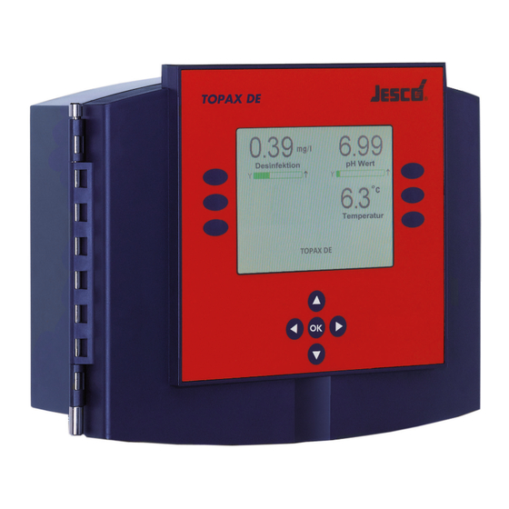
- Page 1 TOPAX ® Two-Channel Controller Operating instructions Read this operating manual before using the equipment. To be retained for future reference.
-
Page 2: Table Of Contents
Two-Channel Controller TOPAX DE Table of Contents 1 Safety Instructions ................3 10 Analogue power outputs 0/4 … 20 mA for remote displays ..28 1.1 General ....................3 11 Log book function ................28 1.2 Identification of safety instructions in the operating manual ..... 3 1.3 Personnel qualification and training ............ -
Page 3: Safety Instructions
Operating instructions 1 Safety Instructions 1.4 Electrical device safety instructions Basic safety precautions should always be followed when installing and 1.1 General using this electrical equipment. These include the following: WARNING! This manual contains essential information for the installation, start-up, operation and maintenance of the equipment. -
Page 4: Safety Instructions For Installation, Maintenance And Inspection
Two-Channel Controller TOPAX DE 2 Before using the equipment 1.8 Safety instructions for installation, maintenance and inspection 2.1 Use for intended purpose The operating company must ensure that all installation, maintenance and inspection work is carried out by qualified and authorised personnel. -
Page 5: Technical Data
Operating instructions 3 Technical data Supply voltage 90 … 264 V AC, 47 … 63 Hz Power consumption Approx. 24 W Housing dimensions 302 x 231 x 108 mm (W x H x D) wall-mounted housing Display Graphic colour display 5.7 inch, 320 * 240 pixels (RGB), with LED backlight (lighting dims automatically after 10 minutes) Keyboard Keyboard with touch keys Measurement inputs... -
Page 6: Recommended Cables
Two-Channel Controller TOPAX DE 3.1 Recommended cables Recommended cables for the different connections and applications: Connections and applications Dimensions Types Mains voltage M20 X 1.5 NYM-I 3 x 1.5 mm (9.1 mm) Relay output (ATE- engine) M20 X 1.5 NYM-I 4 x 1.5 mm (9.8 mm) Relay output (pulse frequency), (pulse length) M16 X 1.5... -
Page 7: Assembly And Installation
Operating instructions 4 Assembly and Installation 4.2 Dimensions 302 mm 4.1 General Notes For installation, the local directions and regulations have to be adhered to. Any mounting position is possible. The ambient conditions are to be maintained in accordance with the technical data. Exposure of the unit to direct heat and sunlight must be avoided. -
Page 8: Technical Components
Two-Channel Controller TOPAX DE 4.4 Technical components 4.4.4 Output board On the output block there are 5 integrated relay output and 3 electronic Besides the main board, the following can be fitted in addition outputs (optocouplers). • up to 2 input components •... -
Page 9: Power Connections
Operating instructions Fig.5: Position and setting of the jumper to activate the RS 485 resistances on the last TOPAX in the network. 4.4.6 TopView software For remote viewing on a PC the manufacturer offers the full version of Fig.4: RS 485 connections on the interface module board, partially obscured by the TopView display program and a freeware version with limited func- the output module tionality. -
Page 10: Topax On The Easypro Water Sampling Station
Two-Channel Controller TOPAX DE IMPORTANT! If possible a continuous cable is to be used from the sensor to the measuring entrance. An extension of the cable by plugs or terminal socket increases the risk of disturbances due to contamination, humidity or excessive transition resistances. -
Page 11: Terminal Clips Of The Main Board And The Technical Components
Operating instructions 4.7 Terminal clips of the main board and the technical components power generator 5-fold input block 3-fold input block Plugin connector to the display circuit board output block DO7 DO6 DO5 + - + - + - + - + - + - + - Alarm relays 20 mA Power Outputs Digital Outputs... - Page 12 Two-Channel Controller TOPAX DE 4.7.3 Input module (3x) Terminal Function Digital inputs Terminal Function Cable colour potential free input measuring water shortage *) Reference electrode Disinfection Reference electrode potential free input filter cleaning *) (with integrated cable) (potentiostatic (Glass): black...
-
Page 13: Input Configuration
Operating instructions 4.8 Input configuration Article name Function Terminal Conductivity Transmitter and Measuring Cell 20/60 mS/cm Conductivity 74 + 75 Diaphragm-covered Measuring Cell Type CD 4 MA Chlorine dioxide 51B + 52B Diaphragm-covered Sensor 4...20 mA Type Cl 4.1 A 2 Free chlorine 51B + 52B Disturbance variable 4-20 mA... -
Page 14: Output Configuration
Two-Channel Controller TOPAX DE 4.9 Output configuration Article name Output Configuration Signal type Terminal C7700 20mA Current output Current output (20mA) analogue C7700 3-p-s Relay (3 step) 3 point step with poti digital EASYZON D/Da Current output Current output (20mA) - Page 15 Operating instructions 4.9.1 Installation example with C 7700 Controller connection Sensors connection Disinfection: C 7700 (servo motor with potentiometer) Disinfection: Potentialstatic electrode pH value: Solenoid-driven dosing pumps pH value: Single-rod measuring cell (Pulse frequency optocoupler) Redox: Single-rod measuring cell Other: Connection of PC interface RS 485 pH value Redox...
- Page 16 Two-Channel Controller TOPAX DE 4.9.2 Installation example with peristaltic pumps Controller connection Disinfection: Peristaltic pump pH value: Peristaltic pump 90 - 264 V AC Suppressors 16 | BA-40400-02-V14...
-
Page 17: Operation And Keyboard Layout
Operating instructions 4.10 Operation and keyboard layout 4.11 First set-up and programming guidelines After correct installation, switch on the power supply. 302 mm The TOPAX is programmed by the manufacturer based on customers’ specs before shipment and is supplied along with a terminal connection diagram. - Page 18 Two-Channel Controller TOPAX DE 4.11.6 Menu 0.4.2: Output Disinfection 4.11.11 Menu 0.6: Terminal connection clips With the arrow keys▲ and ▼ you can select between the options: According to the chosen Options the TOPAX determines the relevant • Servomotor with potentiometer terminal connections and shows this in menus 0.6.1 to 0.6.4 (each by...
-
Page 19: Next Steps
Operating instructions 5 Measuring values inputs NOTICE! At start-up the controller outputs of your will TOPAX This section describes the chemical and physical correlations which are be function-less for approx 60 seconds. This time necessary to understand the behaviour of the measurement inputs. is required to stabilize the electrochemical sensors The measurement inputs are processed for: connected. -
Page 20: Measurement Input Disinfection (Amperometric Measurement Cells)
Two-Channel Controller TOPAX DE 5.1 Measurement input Disinfection (amperometric Encapsulated electrode 20 mA type; measurement cells) type: Cl 4.1 A 2 (for free chlorine) Set measuring range based on type: CD 4 MA (for chlorine dioxide) type of detector To measure the disinfection, amperometric measuring cells are used. -
Page 21: Ph Value Measurement Input
Operating instructions 5.2 pH value measurement input ATTENTION! When operating in a heating water system, electro- 5.2.1 Technical data chemical processes at the measuring electrode may cause a shift of the zero point by means of electro- chemical processes. In this case, a two point calibra- Power output Values tion is required. - Page 22 Two-Channel Controller TOPAX DE bration a buffer solution of pH 6.80 is available. When soaking the Ph- IMPORTANT! electrode in this solution, a voltage of 12 mV should be displayed on Store buffer solutions in a cool and dark place. Con- the TOPAX.
-
Page 23: Measurement Output Redox Potential
Operating instructions 5.3 Measurement output Redox potential 5.4 Temperature measurement input The REDOX potential can be used to control the disinfection perfor- 5.4.1 Technical data mance. Power output Values 5.3.1 Technical data Sensor Pt 100 Measuring range: -50°C – +150°C Power output Values Measuring ac-... -
Page 24: Explanation Of Digital Signal Inputs
Two-Channel Controller TOPAX DE 6 Explanation of digital signal inputs 7 Explanation of measuring values outputs 6.4.1 General 7.1 General It is possible to interrupt the control process and to activate an alarm The TOPAX can be used to regulate the disinfection and the ph value. -
Page 25: Output Restriction
Operating instructions 8 Controller explanation ATTENTION! If during ongoing operation, due to faults or the like, the end position and/or the zero point is not reached 8.1 Definitions after approx. 10 minutes, the “Servo motor alarm” Term Definition error message will be displayed. The error tolerance is coupled to the switching hysteresis of the “3-point actual value (X) The actual value of X of the measurement for the... -
Page 26: Calculation Of Setable Values
Two-Channel Controller TOPAX DE 8.3.2 Example of proportional range and reset time The following formula can be used for calculating reference values: Xp = 50 % (amplification = 2) Xp ~ 0.83 · ΔX / Δt · Tu Tn = 3min Tn ~ 3,3 ·... -
Page 27: Controller Parameters
Operating instructions 9 Alarms 8.5 Controller parameters For Disinfection, pH value, bonded chlorine and conductivity inputs the 9.1 Measurement alarms following settings may be programmed: Con- Xp value Tn value pH value For each measuring input a minimum and a maximum alarm can be troller set. -
Page 28: Analogue Power Outputs 0/4
Two-Channel Controller TOPAX DE 10 Analogue power outputs 0/4 … 20 mA for 11 Log book function remote displays The following activities are stored in the logbook: • Configuration of the initial delivery with date and time For the remote indication of the measured values, TOPAX has a similar •... -
Page 29: Menu Configuration And Main Settings
°C temperature Menu Comment on sub-menu 14:28 06.02.2012 Main menu Topax DE Return to the standard display Target values Sets the setpoints of the configured controllers Fig.18: Standard display of TOPAX Calibration Calibration of all sensors connected to the system... - Page 30 Two-Channel Controller TOPAX DE 12.1.4 Menu 1.1: Target values Select one of the inputs for calibration. The device goes to the relevant menu 1.2.1… 1.2.8.3 The type of calibration (1-point calibration or 2-point calibration) de- 0.39 7.04 26.3 pends on the attached sensor (see also chapter 5), which was defined in the start-up configuration.
- Page 31 Operating instructions 12.1.6 Menu 1.3: Trend representations 0.39 7.04 26.3 0.39 7.02 26.3 mg/l °C mg/l °C preselects Set 1 define Set 2 Set 3 Zoom+ activate (Autoset) Zoom- display 24 h. 1.4.8 Fig.26: Main menu >> status >> presel. Fig.24: Main menu >>...
- Page 32 Two-Channel Controller TOPAX DE Enter the name of the pre-adjustment using the arrow keys ▲ and ▼. Select one of the two control units. The device goes to the relevant menu 2.1.1… 2.1.2. This means: Apply the adjustments relevant to your requirements in the fol- lowing sub-menus to the control unit.
- Page 33 Operating instructions 12.1.11 Menu 2.3: Recorder (analogue outputs 0/4 … 20 mA) TOPAX monitors its inputs. If an unwanted alteration appears on an input value, the alarm is set off. The alarm-setting is configured in this menu: 0.39 7.04 26.3 Menu Function Required specifications...
- Page 34 Two-Channel Controller TOPAX DE 12.1.14 Menu 0.4.0: Configuration For night-time operation: • only useful in a closed circuit. The configuration of TOPAX can be changed, saved and loaded. Existing • it can be manually switched on and off. configuration files are saved on the memory card or loaded from it.
- Page 35 Operating instructions 12.1.16 Menu 5.0.1: hardware status 12.1.23 Menus 5.9 and 5.10: Code und service password Main menu >> menu 2 >> service >> HW status Main menu >> menu 2 >> service >> password and service password The menu of the TOPAX indicates: In these menus you can block the various levels by using a password (a •...
- Page 36 Two-Channel Controller TOPAX DE 12.1.28 menu 5.17: Display Main menu >> menu 2 >> service >> display The menu permits: • Assigning a system name on the display • Switching on / off additional information on the standard display •...
-
Page 37: Default Settings
Operating instructions 13 Default settings 14 Memory card The default configuration by the manufacturer includes the following The memory card transfers and stores language data and logfiles. settings. The inputs are activated according to the part number. The data which is saved on the card can be transferred to a PC by means of a reading device. -
Page 38: Troubleshooting And Diagnostics
Two-Channel Controller TOPAX DE 15 Troubleshooting and diagnostics All errors are indicated in clear text on the display of the TOPAX. If several errors occur simultaneously, the error messages can be viewed with the ▲ and ▼ keys. The following error displays and messages are possible: 15.1 Self-setting alarms... -
Page 39: Terminal Connection Diagram For Own Configurations
Operating instructions 16 terminal connection diagram for own configurations Select here your connection requirement for terminal clips configuration of your TOPAX. Part.-no.:_______________________ Description Part number assembled input module 5-fold input module 3-fold Output board PC interface - RS 485 16.1 measurands Terminal connection clips Input 20 mA power outputs... -
Page 40: Device Revision
Two-Channel Controller TOPAX DE 16.2.3 Digital inputs („Service“ menu – digital inputs) Function Terminal connection clips Configurated „OK“ = closed measuring water shortage 17, 18 „OK“ = opened Level – warning Level – alarm „OK“ = closed Dosing tank Disinfection... -
Page 41: Warranty Claim
Operating instructions 18 Warranty claim Warranty claim Please copy and send it back with the unit! If the device breaks down within the period of warranty, please return it in a cleaned condition with the complete warranty claim. Sender Company: ....................... Phone: ........Date: ......Address: ........................................ -
Page 42: Ec Declaration Of Conformity
(FR) Certificat de conformité aux directives européennes Le constructeur, soussigné: Lutz-Jesco GmbH, Am Bostelberge 19, 30900 Wedemark, déclare qu’à la sortie de ses usines le matériel neuf heru désigné ci-dessous était conforme aux prescriptions des directives européennes énoncées ci-après et conforme aux règles de sécurité et af kr autres règles qui lui sont applicables dans le cadre de l’Union européenne. -
Page 43: Index
Operating instructions 20 Index Manual mode ..........27 Measurement input Disinfection ...... 20 actual value (X) ..........25 measuring water shortage ......24 Alarm delay ........... 33 Menu structure ..........29 Alarms ............27 Motor life ............25 Alarm settings ..........27, 35 Network address .......... - Page 44 Standard Plus Chemie-Kreiselpumpen Zentrifugalpumpen Produkte zur Desinfektion von Schwimmbadwasser auf Basis der Salzwasser-Elektrolyse, Hauswasser- technik Die Lutz-Jesco App für iPads erhalten Sie im iTunes App Store. Alle weiteren Informationen hierzu finden Sie auf www.lutz-jesco.com Stammhaus Ungarn Österreich Niederlande Lutz-Jesco GmbH Lutz-Jesco Üzletág...
Need help?
Do you have a question about the TOPAX DE and is the answer not in the manual?
Questions and answers