Table of Contents
Advertisement
Quick Links
SERVICE MANUAL
Ver 1.1 2002.03
With CORRECTION-1
(9-960-869-91)
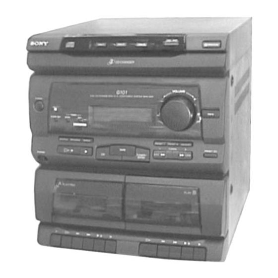
HCD-G101 is the tuner, deck, CD
and amplifier section in MHC-G101.
Sony Corporation
9-960-869-12
2002C0200-1
Home Audio Company
© 2002.03
Pubulished by Sony Engineering Corporation
HCD-G101
Model Name Using Similar Mechanism
CD
CD Mechanism Type
SECTION
Base Unit Type
Optical Pick-up Type
Model Name Using Similar Mechanism
TAPE
DECK
Tape Transport
SECTION
Mechanism Type
SPECIFICATIONS
COMPACT DISC DECK RECEIVER
— 1 —
US Model
Canadian Model
NEW
CX3
KSM-213BCM
KSS-213B/S-N
HCD-H100
DECK-A
TK20FX-SW943-800
DECK-B
TK20FX-SW943-800
Advertisement
Table of Contents

Related Manuals for Sony HCD-G101


Summary of Contents for Sony HCD-G101
- Page 1 HCD-G101 SERVICE MANUAL US Model Canadian Model Ver 1.1 2002.03 With CORRECTION-1 (9-960-869-91) HCD-G101 is the tuner, deck, CD and amplifier section in MHC-G101. Model Name Using Similar Mechanism CD Mechanism Type SECTION Base Unit Type KSM-213BCM Optical Pick-up Type...
-
Page 2: Servicing Note
REPLACE THESE COMPONENTS WITH SONY PARTS FONCTIONNEMENT. NE REMPLACER CES COMPOSANTS WHOSE PART NUMBERS APPEAR AS SHOWN IN THIS QUE PAR DES PIÈCES SONY DONT LES NUMÉROS MANUAL OR IN SUPPLEMENTS PUBLISHED BY SONY. SONT DONNÉS DANS CE MANUEL OU DANS LES SUPPLÉMENTS PUBLIÉS PAR SONY. -
Page 3: Table Of Contents
SAFETY CHECK-OUT TABLE OF CONTENTS After correcting the original service problem, perform the follow- 1. GENERAL ................4 ing safety checks before releasing the set to the customer: Check the antenna terminals, metal trim, “metallized” knobs, screws, 2. DISASSEMBLY and all other exposed metal parts for AC leakage. Check leakage as 2-1. -
Page 4: General
SECTION 1 GENERAL Location of Parts and Controls !¢ !£ !™ !¡ !º !∞ !§ !¶ !• !ª@º@¡ @™ @£ @¢ @∞ @§ @• @¶ #¡ #º @ª 1 Disc tray @º p(stop) button 2 DISC 1 button @¡ CD button 3 DISC 2 button @™... -
Page 5: Disassembly
SECTION 2 DISASSEMBLY Note: Follow the disassembly procedure in the numerical order given. 2-1. CD DOOR CD door craws 1 Pull out the CD tray and remove the CD door with releasing claws into the direction of arrow. 2-2. CD MECHANISM DECK 1 Two screws (B3x8) 7 CD mechanism deck 6 Harness... -
Page 6: Front Panel And Main Board
2-3. FRONT PANEL AND MAIN BOARD 6 Screw (BVTP3x10) 5 Two screws (BVTP3x10) 4 Two screws (BVTP3x10) 8 Screw (BVTP3x10) 2 Connector (CN401) 9 Front panel and Main board 7 Screw (BVTP3x10) 3 Screw (BVTP3x8) HOW TO SET THE POWER CORD 1 Three screws POWER CORD (BVTP3x10) -
Page 7: Cd Tray
2-5. CD TRAY 1 Screw (BVTP3x10) 2 Bracket 3 Screw (BVTP3x10) 4 Bracket 5 CD tray 2-6. CD DECODER BOARD 4 Flat type wire (CN06) 2 Two screws 5 Connector (CN05) (BVTP3x10) 7 CD decoder board 6 Flat type wire (CN01) 3 Two claws 1 Two screws (BVTP3x6) -
Page 8: Base Unit
2-7. BASE UNIT 1 Screw (PTPWH2.6x8) 2 UD-cam 3 Two screws Note: When installing, set to the groove of UD-cam. 4 Base unit — 8 —... -
Page 9: Mechanical Adjustments
SECTION 3 SECTION 4 MECHANICAL ADJUSTMENTS ELECTRICAL ADJUSTMENTS Precaution DECK SECTION 0 dB=0.775V 1. Clean the following parts with a denatured alcohol-moistened swab: 1. Demagnetize the record/playback head with a head damagnetizer. record/playback heads pinch rollers 2. Do not use a magnetized screwdriver for the adjustments. erase head rubber belts 3. - Page 10 2. Turn the adjustment screw and check output peaks. If the peaks 4. After the adjustments, apply suitable locking compound to the do not match for L-CH and R-CH, turn the adjustment screw so parts adjusted. that outputs match within 2 dB of peak. Adjustment Location: L-CH peak...
- Page 11 TUNER SECTION 0 dB=1µV AM Tuning Voltage Adjustment Main board DC voltmeter – Procedure: 1. Set the reception frequency of the unit to 530 kHz. 2. Adjust L105 for 1.2 ± 0.05 V reading on the DC voltmeter. 3. Set the reception frequency of the unit to 1,710 kHz. 4.
- Page 12 FM Tracking Adjustment FM Tuned Level Adjustment Procedure: FM RF SSG 75 Ω coaxial FM RF SSG oscilloscope – Carrier frequency : 98 MHz Modulation : AUDIO 1 kHz, 75 kHz FM ANTENNA terminal SPEAKER terminal (JK302) deviation (100%) (JK101) FM ANTENNA terminal (JK101) : 28 dB (at 75 Ω...
- Page 13 RF Level Check CD SECTION oscilloscope CD DECODER board Note: 1. CD Block is basically constructed to operate without adjustment. Therefore, check each item in order given. TP (RF) 2. Use YEDS-18 disc (3-702-101-01) unless otherwise indicated. CN12 (VC) 3. Use an oscilloscope with more than 10MΩ impedance. 4.
-
Page 14: Diagrams
SECTION 5 DIAGRAMS 5-1. CIRCUIT BOARDS LOCATION DISC board MAIN Board SENSOR board H/P board POWER TRANSFORMER board PANEL board MOTOR (6P) (S) board SW (B) board SW (D) board MOTOR board SW (C) board SW (A) board CD DECODER board R/P SW board —... -
Page 15: Tuner Section
HCD-G101 5-2. BLOCK DIAGRAMS — TUNER SECTION — L OUT TU L FM/AM MPX IC102 R OUT R CH AM IF REC MUTE Q108,109 JK101 CF104 10.7MHz REC OUT FM ANTENNA CF101 CF102 FM IF L101 T101 10.7MHz 10.7MHz FM DET... -
Page 16: Cd Section
HCD-G101 — CD SECTION — OPTICAL PICK-UP BLOCK DIGITAL SIGNAL PROCESSOR, D/A CONVERTER, DIGITAL FILTER DETECTOR IC04 MIX AMP IC05 DIGITAL NLPWM RF 0 DIGITAL DEMODULATOR INTERFACE CD L LPWM FILTER RPWM 1BIT FOCUS/TRACKING R CH NRPWM SERVO, RF AMP... -
Page 17: Deck Section
HCD-G101 — DECK SECTION — PB L CH1/A DECK B MUTE HP901 Q209 PB HEAD PREOUT R CH • R CH is omitted R CH MUTE • Signal path SWITCH REC/PB : PB (DECK A) Q216 CH1/B EQ AMP IC201... -
Page 18: Main Section
HCD-G101 — MAIN SECTION — R-CH POWER AMP SELECTOR IC303 IC301 JK303 PHONES LINE AMP Q305 JK302 TU L SPEAKER REC OUT ELECTRICAL BASS BOOST MUTE CONTROL VOLUME Q309 SWITCH D413,414 Q307 P. ON/OFF TUNER D105,108 POWER SECTION SECTION TUNED... -
Page 19: Power Section
HCD-G101 — POWER SECTION — PT302 POWER TRANSFORMER +5.6V REG +11.5V REG RECT +5.6V Q407 Q405 Q407-Q410 +7.6V REG +7.6V Q406 +5V REG MUTE S401 REG CONTROL CONTROL RELAY SECTION (Page 18) +10.4V REG +11.4V REG +10.4V Q408 Q404 MAIN... - Page 20 — 24 —...
- Page 21 5-3. IC BLOCK DIAGRAMS IC02 TC9173P — CD SECTION — IC01 CXA1782BQ DRIVER SERIAL I/O MUTE CONTROL CONTROL CLOK – LATCH XRST DATA I T.T(M) DATA 0 DRIVER POSI.1 LOADING LEVELS LATCH LATCH POSI.2 LOADING 24 SENS T.T.SW SENSOR – MIRR RF IV AMP1 DFCT...
- Page 22 IC04 CXD2508Q IC102 LA1831 L OUT OSC/FMSD AM RF SMET AM HPF AF DET MPX VCO MPX IN R OUT PL DET MUTE DECORDER RF AMP STEREO SW BUFFER SCOR WFCK AM IF AM DET SBSO EMPHI STEREO DRIVE TRIG EXCK EMPH DIGITAL...
- Page 23 HCD-G101 IC301 LC75392 LVROUT RVROUT LVRIN RVRIN LTOUT RTOUT – LTCOM RTCOM LATCH DECODER SHIFT REGISTER VREF CONTROL — 29 —...
-
Page 30: Ic Pin Function
5-10. IC PIN FUNCTION Pin No. Pin Name Function +5V power supply — • IC601 System Controller, LCD driver (µPD753017AGC) — System clock (4.19 MHz) Pin No. Pin Name Function — Segment output to LCD. 1 to 12 S12 to S23 Latch signal output to CXD2508 XLAT Key control signal output A “H”... -
Page 31: Exploded Views
SECTION 6 EXPLODED VIEWS NOTE: The components identified by mark • Hardware (# mark) list and accessories and pack- • Items marked “*” are not stocked since they are ! or dotted line with mark ! are ing materials are given in the last of this parts list. seldom required for routine service. -
Page 32: Front Panel Section
6-2. FRONT PANEL SECTION LCD601 not supplied Cassette mechanism deck Ref. No. Part No. Description Remark Ref. No. Part No. Description Remark 4-992-794-01 WINDOW (L), CASSETTE 4-992-149-01 KNOB, FUNCTION 4-992-792-01 DOOR (L), CASSETTE 4-992-808-01 HOLDER (L), DOOR * 71 4-992-818-01 LENS, LED 4-992-795-01 WINDOW (R), CASSETTE 4-992-814-01 BUTTON, BASS BOOST 4-992-793-01 DOOR (R), CASSETTE... -
Page 33: Cassette Mechanism Deck Section 1
6-3. CASSETTE MECHANISM DECK SECTION 1 Ref. No. Part No. Description Remark Ref. No. Part No. Description Remark 4-992-133-01 BUTTON, REC 4-992-139-01 BUTTON (B), PLAY 4-992-134-01 BUTTON (A), PLAY 4-992-140-01 BUTTON (B), REW 4-992-135-01 BUTTON (A), REW 4-992-141-01 BUTTON (B), F.F 4-992-136-01 BUTTON (A), F.F 4-992-142-01 BUTTON (B), STOP/EJECT 4-992-137-01 BUTTON (A), STOP/EJECT... -
Page 34: Cassette Mechanism Deck Section 2
6-4. CASSETTE MECHANISM DECK SECTION 2 not supplied not supplied M901 SW202 not supplied HE901 SW203 HRP901 supplied not supplied SW204 not supplied HP901 not supplied not supplied not supplied Ref. No. Part No. Description Remark Ref. No. Part No. Description Remark 9-980-282-01 E HEAD SCREW... -
Page 35: Cd Mechanism Deck Section 1
6-5. CD MECHANISM DECK SECTION 1 M103 Ref. No. Part No. Description Remark Ref. No. Part No. Description Remark * 201 1-666-451-11 MOTOR BOARD 4-992-183-01 SCREW, RELAY GEAR (B) 3-669-480-11 + PTPWH 2 4-992-168-01 TRAY, CHANGER BASE 4-992-174-01 GEAR, CHANGE 4-992-180-01 PLATE, BLIND 4-992-184-01 WASHER, CHANGE GEAR 4-992-181-01 LEVER, SENSOR (SW) -
Page 36: Cd Mechanism Deck Section 2
6-6. CD MECHANISM DECK SECTION 2 not supplied M104 Base unit block Ref. No. Part No. Description Remark Ref. No. Part No. Description Remark 1-769-856-11 WIRE (FLAT TYPE) (5 CORE) 4-992-193-01 LEVER, SW 4-992-190-01 UD-CAM * 263 1-666-450-11 SW (D) BOARD 4-992-191-01 UD-GEAR * 264 1-666-449-11 SW (C) BOARD... -
Page 37: Base Unit Section (Ksm-213Bcm)
6-7. BASE UNIT SECTION (KSM-213BCM) not supplied M102 M101 Les composants identifiés par The components identified by mark ! or dotted line with mark une marque ! sont critiques pour ! are critical for safety. la sécurité. Replace only with part number Ne les remplacer que par une specified. -
Page 38: Electrical Parts List
SECTION 7 CD DECODER ELECTRICAL PARTS LIST Note: • SEMICONDUCTORS • Due to standardization, replacements in the parts list The components identified by In each case, u: µ , for example: may be different from the parts specified in the mark ! or dotted line with mark uA...: µ... - Page 39 CD DECODER Ref. No. Part No. Description Remark Ref. No. Part No. Description Remark 1-249-843-11 CARBON 3.3K 1/4W < IC > 1-249-855-11 CARBON 1/4W 1-247-903-00 CARBON 1/4W IC01 8-752-069-56 IC CXA1782BQ IC02 8-759-388-27 IC TC9173P 1-249-855-11 CARBON 1/4W IC03 8-759-429-31 IC BA5941FP 1-247-879-11 CARBON 100K 1/4W...
- Page 40 CD DECODER DISC MAIN Ref. No. Part No. Description Remark Ref. No. Part No. Description Remark 1-249-839-11 CARBON 2.2K 1/4W C112 1-162-282-31 CERAMIC 100PF 1-249-839-11 CARBON 2.2K 1/4W C114 1-164-159-11 CERAMIC 0.1uF 1-249-420-11 CARBON 1.8K 1/4W F C115 1-162-294-31 CERAMIC 0.001uF C116 1-130-014-00 FILM...
- Page 41 MAIN Ref. No. Part No. Description Remark Ref. No. Part No. Description Remark C211 1-124-903-11 ELECT C212 1-124-903-11 ELECT C332 1-124-572-11 ELECT 100uF C333 1-104-665-11 ELECT 100uF C334 1-124-903-11 ELECT C213 1-162-294-31 CERAMIC 0.001uF C214 1-162-294-31 CERAMIC 0.001uF C335 1-124-903-11 ELECT C215 1-162-301-11 CERAMIC 0.0015uF 30%...
- Page 42 MAIN Ref. No. Part No. Description Remark Ref. No. Part No. Description Remark C420 1-161-494-00 CERAMIC 0.022uF < FUSE, FUSE HOLDER > C421 1-104-665-11 ELECT 100uF C422 1-161-494-00 CERAMIC 0.022uF ! F401 1-576-107-12 FUSE (3.15A/250V) * F401H 1-533-293-11 FUSE HOLDER C423 1-104-665-11 ELECT 100uF...
- Page 43 MAIN Ref. No. Part No. Description Remark Ref. No. Part No. Description Remark Q302 8-729-194-57 TRANSISTOR 2SC945-P R141 1-247-839-11 CARBON 2.2K 1/4W Q304 8-729-194-57 TRANSISTOR 2SC945-P R142 1-247-839-11 CARBON 2.2K 1/4W R143 1-247-839-11 CARBON 2.2K 1/4W Q305 8-729-194-57 TRANSISTOR 2SC945-P Q306 8-729-194-57 TRANSISTOR 2SC945-P R144...
- Page 44 MAIN Ref. No. Part No. Description Remark Ref. No. Part No. Description Remark R342 1-247-855-11 CARBON 1/4W R251 1-247-847-11 CARBON 4.7K 1/4W R252 1-247-871-11 CARBON 1/4W R343 1-247-879-11 CARBON 100K 1/4W R253 1-247-871-11 CARBON 1/4W R344 1-247-889-00 CARBON 270K 1/4W R256 1-249-417-11 CARBON 1/4W F...
- Page 45 MOTOR MOTOR (6P) (S) MAIN PANEL Ref. No. Part No. Description Remark Ref. No. Part No. Description Remark A-4403-097-A PANEL MOUNTED BOARD, COMPLETE R205A 1-247-827-11 CARBON 1/4W ****************************** R206A 1-247-827-11 CARBON 1/4W 4-980-832-01 COVER, LED < SWITCH > 4-992-826-01 PLATE, DISPLAY 4-992-827-01 HOLDER, DISPLAY S401 1-515-921-11 RELAY (12V)
- Page 46 PANEL POWER TRANSFORMER R/P SW Ref. No. Part No. Description Remark Ref. No. Part No. Description Remark < DIODE > S606 1-572-481-11 SWITCH, KEY BOARD (1 KEY)(DBFB) LED601 8-719-300-79 DIODE SEL1213C (DBFB) S607 1-571-914-21 SWITCH, KEY BOARD (VOLUME +) S608 1-571-914-21 SWITCH, KEY BOARD (VOLUME –) <...
- Page 47 HCD-G101 SENSOR SW (A) SW (B) SW (C) SW (D) Ref. No. Part No. Description Remark Ref. No. Part No. Description Remark MISCELLANEOUS 1-666-440-11 SENSOR BOARD ************* ************ 1-559-583-11 CORD, POWER < IC > 1-773-152-11 WIRE (FLAT TYPE) (21 CORE)
- Page 48 HCD-G101 1997.08...
- Page 49 HCD-G101 MEMO – 2 –...
- Page 50 HCD-G101 Printing Method for Large Sized Documents Such As Circuit Diagrams Printing the page that exceeds A4-size two pages (or letter size) is possible by specifying the print range. (Acrobat Reader Version 4.0 or later) 1. The enlarged print is made, if a smaller range than A4 size is specified and the A4 size is selected as a print paper.
- Page 51 HCD-G101 REVISION HISTORY Clicking the version allows you to jump to the revised page. Also, clicking the version at the upper right on the revised page allows you to jump to the next revised page. Ver. Date Description of Revision 1997.
Need help?
Do you have a question about the HCD-G101 and is the answer not in the manual?
Questions and answers