Table of Contents
Advertisement
Operating instructions
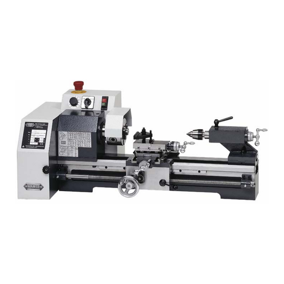
Universal Mechanic Lathes
D4000 E
CC-D4000 E
Walter Blombach GmbH
Tool and Machine Factory
D-42899 Remscheid - Am Blaffertsberg 13 - Phone.: (02191) 597- 0 - Fax: (02191) 597 – 40 - E-Mail: info@wabeco-remscheid.de
D-54673 Neuerburg - WABECO Str. 1-10 - Phone.: (06564) 9697-0 - Fax: (06564) 9697-25 - E-Mail: neuerburg@wabeco-remscheid.de
www.wabeco-remscheid.de
Advertisement
Table of Contents

Related Manuals for WABECO D4000 E


Summary of Contents for WABECO D4000 E
-
Page 1: Operating Instructions
Tool and Machine Factory D-42899 Remscheid - Am Blaffertsberg 13 - Phone.: (02191) 597- 0 - Fax: (02191) 597 – 40 - E-Mail: info@wabeco-remscheid.de D-54673 Neuerburg - WABECO Str. 1-10 - Phone.: (06564) 9697-0 - Fax: (06564) 9697-25 - E-Mail: neuerburg@wabeco-remscheid.de... -
Page 2: Table Of Contents
Index EC – Conformity Declaration Technical Data Drawing and list of parts Lubricating plan Arrangement of take-up gears for a 1 mm thread pitch (slope) Diagram for reading off speed Position of tumbler gear when cutting LH thread Position of take-up gears for automatic feed Operating elements Headstock with gear and tumbler gear 2.7.1... - Page 3 Index 9.2.4 Speed transmission from main spindle to leadscrew 9.2.5 Tumbler wheel adjustment 9.2.6 Protective cover for chuck Bed with leadscrew drive 9.3.1 Overload coupling 9.3.2 Setting the bearing play on the leadscrew Tooling carriages 9.4.1 Cross slide 9.4.2 Top slide Tailstock Applications 10.1...
-
Page 4: Ec – Conformity Declaration
D-42871 Remscheid - Postfach 12 01 61 - Phone: (02191) 597- 0 - Fax: (02191) 597 - 40 D-54673 Neuerburg - WABECO Str. 1-10 - Phone: (06564) 9697-0 - Fax: (06564) 9697-25 We hereby declare that the universal lathes specified below... - Page 5 Outlay Dear customer! Congratulations on choosing the WABECO Universal Lathe. We have taken great care in its manufacture and we have given it a thorough quality control test. These operating instructions are to help you to work with it safely and properly.
-
Page 6: Technical Data
Technical Data Working range Centre distance ............350 mm Centre height.............. 100 mm Largest turning diameter over bed......200 mm Largest turning diameter over slide ......120 mm Work spindle Drive output ..............1,4 Kw, 220V, 50Hz Infinetely variable spindle speed......... 45 –... -
Page 7: Drawing And List Of Parts
Drawing and list of parts Lubricating plan all 8 working hours all 8 working hours Drawing and list of parts... -
Page 8: Arrangement Of Take-Up Gears For A 1 Mm Thread Pitch (Slope)
Arrangement of take-up gears for a 1 mm thread pitch (slope) (LH thread) Drawing and list of parts... -
Page 9: Diagram For Reading Off Speed
Diagram for reading off speed m/min 4000 3000 2000 2500 1600 1000 1250 n 1/min 8 10 60 80 100 160 200 Diagram 1250 1500 1700 1950 2200 2300 100% 2300 Drawing and list of parts... -
Page 10: Position Of Tumbler Gear When Cutting Lh Thread
Position of tumbler gear when cutting LH thread Tumbler wheel Clamping screw Drawing and list of parts Position of take-up gears for automatic feed... - Page 11 Drawing and list of parts Operating elements...
-
Page 12: Operating Elements
Potentiometer turning knob for choosing the speed of the driving electric motor Emergency OFF switch Reversing switch for changing direction of turn – main spindle Master switch with undervoltage release Opening and closing of clasp nut Chuck handwheel für longitudinal support Clamping lever for tool clamping plate Ball-ended crank for adjusting of cross slide Chuck for quick adjusting of cross slide... - Page 13 Drawing and list of parts Headstock with gear and tumbler gear 2.7.1 Headstock...
-
Page 14: Headstock With Gear And Tumbler Gear
Part-No. Pcs. Order-No. Designation 10400101 Tapered roller bearing 10400104 Headstock 10400105 Flange, front 10400106 Work spindle 10400107 Oil wiper ring 10400108 Feather key 10400109 Flange, rear 10400110 Distance ring 10400111 Belt pulley 10400112 Belt pulley 10400113 Adjusting nut 10400114 Countersunk screw 11810005 Lubricating nipple 10400116... - Page 15 Drawing and list of parts Bed with leading spindle drive and change gear quadrant 2.8.1 Bed with leading spindle drive Designation Part-No. Pcs. Order-No.
-
Page 16: Bed With Leading Spindle Drive And Take-Up Gear Cutter
10400201 Toothed racket 10400203 10400204 Supporting bearing, front 10400205 Bushing 10400206 Leading spindle 10400207 Supporting bearing, rear 10400208 Thrust block, loose 10400210 Bushing 10400211 Hexagon socket screw 10400212 Hexagon socket screw 11810005 Lubricating nipple 10400214 10400217 Disc 10400218 10400219 Hexagon socket screw 2.8.2 Take-up gear cutter Designation... - Page 17 Drawing and list of parts CNC control drive Z-axis Designation Part-No. Pcs. Order-No. Belt pulley Z30 Threaded pin Motor sheet metal Earthing screw Motor housing...
-
Page 18: Cnc Control Drive Z-Axis
Step motor Washer Earthing screw Hexagon nut Lid for motor housing Earthing screw Belt pulley Z12 Zylindrical pin Washer for tooth wheel Circlip Toothed belt Protective cover Drawing and list of parts CNC control drive Z-axis... - Page 19 Drawing and list of parts 2.10 Tool carriage 2.10.1 Saddle apron with cross slide Designation Part-No. Pcs. Order-No. 10400401 Lower part of cross slide 10400402 10400403 Disc 10400404 Hexagon bolt 10400405 Upper part of cross slide...
-
Page 20: Tool Carriage
10400406 Adjustment rail 10400407 Felt 10400408 Felt 10400409 Felt clamp 10400410 Felt clamp 10400411 Hexagonal socket bolt 10400412 Hexagon bolt 10400413 Saddle apron 10400414 Hexagonal socket bolt 10400415 Cleap holder 10400416 Clasp nut 10400417 10400417 Guide rail 10400419 Feather key clasp holder 10400420 Switch lever 10400421... -
Page 21: Top Slide
10400456 Spindle square 10400457 Ball-ended crank 2.10.2 Top slide Designation Part-No. Pcs. Order-No. 10400501 Top slide lower part 10400502 Guide ring 10400503 10400504 Hexagonal socket screw 10400505 Clamping piece 10400506 10400507 Top slide upper part 10400508 Adjustment rail 10400509 Thread bolt 11700056 Threaded pin 10400511... - Page 22 Drawing and list of parts 2.10 Tool carriage Saddle apron...
-
Page 23: Cnc Control Drive X-Axis
Top slide Drawing and list of parts 2.11 CNC control drive X-axis Designation Part-No. Pcs. Order-No. Feather Ball Zylindrical pin Ball-ended crank Scale ring Earthing screw Belt pulley Threaded pin Motor mechanism plate... - Page 24 Clamping plate Auxiliary motor Step motor Saucer-head screw Washer Belt pulley Flanged wheel Threaded pin Hexagon nut Toothed belt Protection cab Earthing screw Drawing and list of parts 2.11 CNC control drive X-axis...
- Page 25 Drawing and list of parts 2.12 Tailstock Designation Part-No. Pcs. Order-No. 10400601 Tailstock 10400602 Upper part of shim 10400603 Lower part of shim 10400604 Quill 10400605 Scale 10400606 Threaded pin 10400607 Ball-ended crank 10400608 Lower part of tailstock 10400609 Threaded pin 10400610 Shim 10400611...
- Page 26 10400615 Spindle 10400616 Flange 11810005 Lubricating nipple 10400618 Hexagon socket screw 11850002 Feather 11810004 Ball 10400621 Threaded pin 10400622 Pressure sping 10400623 Scale support 10400624 Scale ring 10400625 Ball-ended crank 10400626 Drawing and list of parts 2.12 Tailstock...
-
Page 27: Motor Frame
Drawing and list of parts 2.13 Motor frame Designation Part-No. Pcs. Order-No. 11800001 Master switch 11800008 Emergency OFF switch 11800014 Final switch 11800005 Bottom plate 10400705 Motor 10400706 Motor frame 10400707 Platina holder 11700057 Earthing screw 10400709 Base plate 11800004 Potentiometer complete 11700002 10400720... - Page 28 11700051 Countersunk heard screw 10400728 Covering motor frame 11700026 Hexagon socket screw 11700059 Hexagon socket screw 10400731 Protection cab 11700026 Hexagon socket screw 11700060 Washer 11700061 Hexagon socket screw Drawing and list of parts 2.13 Motor frame...
-
Page 29: Circuit Diagram
Circuit diagram... -
Page 30: Delivery And Installation
mains plug emergency OFF main switch reversing switch switch for protection cap potentiometer Date Danger motor control electronics Delivery and installation The lathes are carefully packed in our factory. Please check the following on delivery: whether the packaging has been damaged and/or:... -
Page 31: Conditions For Best Working Results
whether the drilling and milling machine shows signs of transport damage or if there are grounds for complaint. In this case we request your immediate notification. Claims made at a later date cannot be acknowledged. The lathes must be installed on an appropriate, level and firm base. This would be, for example: a base cabinet such as in our accessories programme own work bench as long as it is strong enough to carry the weight of the machine without warp-... -
Page 32: Starting-Up And Maintenance
Fix the machine on a sturdy, level support. Use sharp processing tools. Adjust speed setting and feed to fit the material and diameter of the tool Clamp the tools so that the clamping position is as near possible to the work- piece. -
Page 33: Guidelines For The Periodical Maintenance Of The Machine
The lathe should be lubricated every 8 operating hours according to the lubricating schedule (2.1). Lubricating points 3 (bed guide), 4 (dove-tail guide cross slide), 5 (dove-tail guide top slide) and 7 (tailstock barrel) with the help of an oil can and a standard lubricating oil, moving the saddle and the barrel backwards and forwards while doing so. -
Page 34: Description Of The Machine
14. When working between centres, always centre well in order to avoid a flying-out of the work- piece. In addition, check the tightening screw of the tailstock to make sure it is tight. 15. When working with automatic advance take care that the cross table does not touch the chuck or the tailstock. -
Page 35: Spindle Head
• Massive large-dimensioned grey cast iron machine bed. • Sturdy cross ribbing makes the bed extremely stable and enables you to work with no oscilla- tions. • The wide prismaticatic guide is ground. • Cross and longitudinal support with dove-tail guides and adjusting rails. •... -
Page 36: Change Of Speed
All the electrical equipment is housed in the box situated at the rear side of the headstock. The AC motor is supplied already installed. The shock-proof plug can be connected directly via a shock-proof socket to the 220 V mains supply. All 230V machines are fitted with a master switch with undervoltage release, i.e. -
Page 37: Protective Cover For Chuck
As shown in the diagram (2.2) the right-hand wheel on the tumbler gear is engaged in the gear- wheel of the main spindle. This setting is for LH threads, i.e. if the spindle is turning in an anti-clockwise direction (looking at the chuck), then the tooling carriage will move away from the chuck. -
Page 38: Cross Slide
9.4.1 Cross slide The cross slide is situated at the front on a prismaticatic guide and at the back on a flat surface guide. The slide is held to the bed from below by means of guide rail (46). At the front on the RH side is the cylindrical screw (39). -
Page 39: Tailstock
As described in the case of the cross slide, the top slide has also got a read-off scale for its travel path. Here, one notch corresponds to 0.05mm of movement. Since you do not work with diameters on the top slide, then this 0.05 mm corresponds to the actual path. A complete turning of the crank corresponds to a path of 1mm. - Page 40 In the case of longitudinal turning tool moves parallel to the axis of the workpiece. For roughing at longitudinal turning the use of either a straight or arcuated turning tool is favourably. For smoothing the use of pointed or broad turning tools is favourable. Transverse turning: The tooling of the face is known as transverse turning.
-
Page 41: Thread Cutting And Automatic Feed
For the reason of the power at the turning chisel take care that the tool is short and fast fixed. If the lever arm is to long the turning chisel curves and springs back. The cutting part enters uneven into the workpiece and is producing a waved surface. Take care that the turning chisel is placed on the middle of the turning piece. -
Page 42: Altering The Feeds Or Thread Pitches
For the purpose of automatic longitudinal turning there are two feed rates, being at your disposal: 0,085 mm and 0,16 mm/revolution. (Upon delivery, the gears producing a feed of 0,085 mm/revolution have been put on). Putting on different combinations of gears enables you to cut metric thread ranging from 0,4 to 3,0 mm in pitch. - Page 43 When altering the feeds or thread pitches, proceed as follows: Changing the feed from 0,085 mm to 0,16 mm Loosen the fixing screw D of the change gear quadrant. (First loosen the knurled screw at the front of the headstock and open the protective cover.
-
Page 44: Lh Thread
Changing the feed from 0,085 mm to a metric pitch of 1,5 mm Start the procedure exactly as already described. Only toothed belt pulley Z 48 on bolt A has additionally to be substituted by toothed belt pulley Z 34. The feed is switched over via the lever grip on the front side of the cam box. -
Page 45: Tool Holder With Conical Sleeve
Danger of accident Do not try to clamp larger workpieces. The chucking power is then too low and the jaws can detach themselves. Mounting of turning jaws: The jaws and guides are numbered from 1-3. Open the chuck by means of the chuck key until the jaws loosen. - Page 46 The square turret head is used instead of the clamping plate in order to clamp the tools. Four turning tools can be changed simultaneously. By swivelling the turret head by 90 degrees each time, the required turning tool can quickly be brought into its working position. Advantage: Paring chisels are always in the centre after being adjusted just once.
- Page 47 The unit for lubrication coolant consists of: 1. Tray with lubrication coolant sump which collects the lubrication coolant mixture for the feed pump. Contents generally 19 litres. 2. Feed pump with the following electrical data - nominal voltage 230 V - frequency 50 Hz - nominal current input 0,4A - nominal output 0,07 kW...
- Page 48 Declaration of noise levels in accordance with DIN EN 24871 (German Industrial Standard) Noise levels while running idle Acoustic capacity level 67 dB (A) Sound pressure level on operator’s ear 63 dB (A) The stated values reflect emission levels and not necessarily working levels. Although there is a corre- lation between the level of emission and the level of stress, this cannot be used reliably in order to de- termine whether additional safety measures are necessary or not.
Need help?
Do you have a question about the D4000 E and is the answer not in the manual?
Questions and answers