Table of Contents
Advertisement
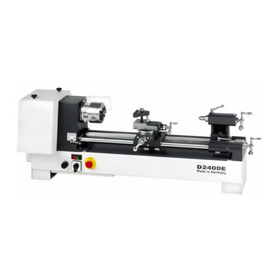
D2400 E
D-42899 Remscheid Am Blaffertsberg 13 Phone: 0049 (2191) 597-0
D-54673 Neuerburg
WABECO Str. 1-10 Phone: 0049 (6564) 9697-0 Fax: 0049 (6564) 9697-25
Operating instructions
Universal Lathes
D2000 E
Walter Blombach GmbH
Tool and Machine Factory
www.wabeco-remscheid.de
D3000 E
Fax: 0049 (2191) 597-40
E-Mail: info@wabeco-remscheid.de
E-Mail: neuerburg@wabeco-remscheid.de
Advertisement
Table of Contents

Subscribe to Our Youtube Channel
Related Manuals for WABECO D2000E


Summary of Contents for WABECO D2000E
-
Page 1: Operating Instructions
D3000 E Walter Blombach GmbH Tool and Machine Factory D-42899 Remscheid Am Blaffertsberg 13 Phone: 0049 (2191) 597-0 Fax: 0049 (2191) 597-40 E-Mail: info@wabeco-remscheid.de D-54673 Neuerburg WABECO Str. 1-10 Phone: 0049 (6564) 9697-0 Fax: 0049 (6564) 9697-25 E-Mail: neuerburg@wabeco-remscheid.de www.wabeco-remscheid.de... -
Page 2: Table Of Contents
Index EC-Conformity Declaration Product range Universal Lathe D2000 E Universal Lathe D2400 E Universal Lathe D3000 E Drawings and list of parts Headstock Support with motor and cover for D2400 E, D3000 E Leading spindle drive for D2000 E, D2400 E Leading spindle drive for D3000 E Antrieb mit Vorgelege zu D2000 W Cross table... - Page 3 Index 10.2.1 General note 10.2.2 Application of change gears 10.2.3 Altering the feeds or thread pitches 10.2.4 Changing of feeds or thread pitche D3000 E Pair of toothed wheels for left-hand thread Angle plate with milling table Three jaw-chuck and four jaw-chuck Tool holder with conical sleeve Steady and follow rest Square turret head...
-
Page 4: Ec-Conformity Declaration
Fax: 0049 (6564) 9697-25 We hereby declare that the universal milling and drilling machines specified below Universal Lathes Typ: D2000E – D2400 E – D3000 E meet the following regulation requirements for standard serie production EC directive for machines EWG 91/68 and 89/392... - Page 5 Outlay Dear customer! Congratulations on choosing the WABECO Universal Lathe. We have taken great care in its manufacture and we have given it a thorough quality control test. These operating instructions are to help you to work with it safely and properly.
-
Page 6: Universal Lathe D2000 E
Technical Data Universal Lathe D2000 E Working range Centre distance ............350 mm Centre height.............. 110 mm Work spindle Power ................. 1,4 kW, 230 V, 50 Hz Spindle speed infinetely variable........ 30 – 2300 r.p.m. Spindle bore ............... 20 mm optional 30 mm Taper in spindle nose.......... -
Page 7: Universal Lathe D2400 E
Technical Data Universal Lathe D2400 E Working range Centre distance ............. 500 mm Centre height..............110 mm Work spindle Main drive..............electronic adjustable motor Power ................1,4 Kw, 230V, 50 Hz Spindle speed infinetely variable........30 – 2300 r.p.m. Spindle bore ..............20 mm optional 30 mm Taper in spindle nose.......... -
Page 8: Universal Lathe D3000 E
Technical Data Universal Lathe D3000 E Working range Centre distance ............. 500 mm Centre height..............110 mm Work spindle Main drive..............electronic adjustable motor Power ................1,4 Kw, 230V, 50 Hz Spindle speed infinetely variable........30 - 2300 r.p.m. Spindle bore ..............20 mm Optional 30 mm Taper in spindle nose.......... -
Page 9: Drawings And List Of Parts
Drawings and list of parts Headstock for D2000 E, D2400 E and D3000 E Part-No. Order-No. Designation 10200011 Headstock 1124 10201124 Bronze bushing 1128 10201128 Bronze bushing 10200111 Spindle with flange 1118 10201118 Bearing cap 11181 10211181 Hexagon socket screw 11121 10211121 Feather key... - Page 10 Drawings and list of parts Support with motor and protective cover for D2400 E and D3000 E Part-No. Order-No. Designation 10200125 Cover 1251 10201251 Stud bolt + radial nut 1252 10201252 Support 1253 10201253 Potentiometer 1254 10201254 Master switch with undervoltage release 1255 10201255 Switch right/left...
- Page 11 Drawings and list of parts Support with motor and protective cover for D2400 E and D3000 E...
- Page 12 Drawings and list of parts Leading spindle drive for D2000 E and D2400 E Part-No. Order-No. Designation 1119 10201119 Lubricating nipple 1145 10201145 Toothed belt Z 120 XL037 1146 10201146 Toothed belt Z 140 XL037 1147 10201147 Hexagon socket screw + washer 1149 10201149 Quadrant holder...
- Page 13 Drawings and list of parts Leading spindle drive for D2000 E and D2400 E...
-
Page 14: Leading Spindle Drive For D3000 E
Drawings and list of parts Leading spindle drive for D3000 E Part-No. Order-No. Designation 10300001 D.c. Motor 10300002 Toothed belt 10300003 Toothed belt pulley 10300004 Motor bearing 10300005 3 screws 10300006 Bracket 10300007 2 scres 10300008 2 adjusting nuts 10300009 Pressure ring 10300010 Bushing... - Page 15 Drawings and list of parts Leading spindle drive for D3000 E...
- Page 16 Drawings and list of parts Leading spindel drive with gear motor for D2000 E Part-No. Order-No. Designation 1152 10101152 Support 10100119 with A.C. motor 10101120 with rotary current motor 11912 10111912 Bearing plate 10100116 Mounting support of quadrant 1161 10101161 Hexagon socket screw 11471 10111471...
- Page 17 Drawings and list of parts Leading spindle drive with gear motor for D2000 E...
-
Page 18: Cross Table
Drawings and list of parts Cross table Part-No. Order No. Designation 10200311 Lower part of cross slide 3111 10203111 Nut holder 31111 10231111 Bolts + washers 31112 10231112 Bronze nut 3112 10203112 Bronze nut 3113 10203113 Shim 31131 10231131 Clamping bolt 3114 10203114 Wiper ring... - Page 19 Drawings and list of parts Cross table...
-
Page 20: Tailstock
Drawings and list of parts Tailstock Part-No. Order-No. Designation 10200041 Lower part of tailstock 10200411 Shim 10200412 Capstan with stud bolt 10200414 Washer 10200415 Hexagon nut 10200042 Upper part of tailstock 10200421 Quill 10200422 Flange 1151 10201151 Hexagon socket screw 10200423 Spindle 4231... -
Page 21: Rear Support With Guide Rods
Drawings and list of parts Rear support with guide rods Part-No. Order-No. Designation 10200005 Rear support (only the cast iron part) 10200051 Guide rods 10200052 Feed spindle 10200522 Washer 10200523 Axial needle bearing 31212 10231212 Ball-ended crank 4231 102H4231 Spacer sleeve 10200524 Bronze bushing 10200053... -
Page 22: Circuit Diagram
Block circuit diagram for D2000 E and D2400 E mains plug emergency OFF main switch reversing switch switch for protection cap potentiometer Date Danger motor control electronics... - Page 23 Block circuit diagram for D3000 E...
-
Page 24: Delivery And Installation
Delivery and installation The lathes are carefully packed in our factory. Please check the following on delivery: whether the packaging has been damaged and/or: whether the lathes shows signs of transport damage or if there are grounds for complaint. In this case we request your immediate notification. Claims made at a later date cannot be acknowledged. -
Page 25: Starting-Up And Maintenance
Starting-up and maintenance Fix the machine on a sturdy, level support Use sharp processing tools Adjust speed setting and feed to fit the material and diameter of the tool Clamp the tools so that the clamping position is as near possible to the workpiece Clamp the workpieces fast and without vibrations. -
Page 26: Safety Instructions
Safety Instructions The feed line for the motor may only be connected to a shock-proof socket or junction box. (Have the socket or junction box checked by an electrician beforehand; protection against children being able to put into operation). The socket or junction box must be close enough to the equipment, that the current-carrying cable is subjected to no tensile strain whatsoever. -
Page 27: Startup And Maintenance
Startup and Maintenance Electrical equipment The lathes are fitted with a master switch with undervoltage release, i.e. this switch must be switched on before the machine can be switched on via the reserving switch. The master switch must also be switched on again following a power failure. ON - OFF lever for automatic feed NOT-AUS... -
Page 28: Maintenance
Startup and Maintenance Lubrication Prior to every putting into operation all lubricating points of the lathe must receive a grease for roller bearings having commercial quality. Both guiding bars have to be greased, too, preceding every putting into operation. The two dovetail guides of the cross slide, the threaded spindles of the cross slide accessible from below, the feed rod as well as the tailstock quill have to be greased at intervals of 100 service tours each using lubricating oil. -
Page 29: Initial Cleaning Of The Machine
Startup and Maintenance Initial cleaning of the machine Prior to putting the machine into operation for the first time all maked parts have to be cleaned applying petroleum or gasoline used for cleaning, because these parts have been treated with slushing oil before leaving the factory. -
Page 30: Compound Rest
Startup and Maintenance Compound rest The compound rest consists of a longitudinal and a transverse slide rest. Its dovetail guides are ajustable. hexagon socket screw for tightening the compound rest take-up screw + counter nuts longitudinal slide take-up screw + counter nuts transverse Compound rest... -
Page 31: Tailstock
Startup and Maintenance Tailstock The tailstock is attached to the slide bars in such a way that it is slidable. It can be easily tightened in any position by screwing the lower T-handle (4251). It can be separated into barrel and base. By loosening the spanner bolt (424), the tailstock barrel can be pushed to either side by up to 10 mm and is, therefore, suitable for the turning of slight tapers. -
Page 32: Speed Regulation
Speed regulation Speed selection The spindle speed is to be selected according to the type of material and the diameter of the work piece: ⇒ Small diameter relatively high speed ⇒ Large diameter low speed The cutting speed is the result of speed and diameter. With a known and required cutting speed, the necessary spindle speed can be calculated in the following way: cutting speed (V) x 1000... -
Page 33: Speed Setting For Working With Brass, Copper
Speed regulation 9.1.3 Speed Setting for Working with Brass, Copper workpiece- Ø approx. r.p.m.. cutting speed m/min 10 mm 2300 20 mm 1270 40 mm 60 mm 80 mm 100 mm Changing of speed Rotational speed 45 - 2300 min -1 : The rotational speed of the work spindle can be infiniely varied between 45 and 400 rpm in the 1. -
Page 34: Applications
Applications 10.1 Longitudinal and transverse turning Longitudinal turning: In the case of longitudinal turning tool moves parallel to the axis of the workpiece. For roughing at longitudinal turning the use of either a straight or arcuated turning tool is favourably. Transverse turning: The tooling of the face is known as transverse turning. -
Page 35: Thread Cutting And Automatic Feed
The connection between the feed gear mechanism and the lead screw is made by the translating gear wheels (extras at D2000, D2000E and D2400) included in the attachments. By setting various combinations of gears it is possible to cut a metric right-hand thread with a pitch of 0,4 mm - 3 mm and an inch-system right-hand thread with a pitch of 10Z/1"... -
Page 36: General Note
Applications 10.2.1 General note Feed: The feed is switched on by means of the T-handle on the front side of the spindle head. When cutting threads it must be remembered that the feed remains on throughout to ensure that the turning chisel always returns to the same positon when cutting more than one thread. -
Page 37: Altering The Feeds Or Thread Pitches
Applications 10.2.2 Application of change gears - optional for D2000 and D2400 E Table automatic longitudinal feed for D2000 - D2400 E 0,085 0,16 10.2.3 Altering the feeds or thread pitches for D2000 E and D2400 E When altering the feeds or thread pitches, proceed as follows: Changing the feed from 0,085 mm to 0,16 mm Loosen the fixing screw D of the change gear quadrant. - Page 38 Applications 10.2.3 Altering the feeds or thread pitches for D2000 E and D2400 E Changing the feed from 0,085 mm to a metric pitch of 1,5 mm a. - c. Start the procedure exactly as already described under pos. 1, a-c, expect for the hexagonal nut being removed as well from the shearing bushing C, as described under pos.
- Page 39 Applications 10.2.4 Changing of feeds or thread pitch for D3000 E Working with the automatic longitudinal feed Turn the handle (19) on the symbol longitudinal turning. For the connection of the clutch disk turn with with the handle (31212) a little. Switch-on the direction switch on the right of the substructure.
-
Page 40: Pair Of Toothed Wheels For Left-Hand Thread
Pair of toothed wheels for left-hand thread To cut left-hand threads, the toothed belt gear No. 11214 on bolt A is to be exchanged for the toothed gear Z 75 and the toothed belt gear No. 1114 on the work spindle exchanged for the toothed gear Z 50. -
Page 41: Angle Plate With Milling Table
Angle plate with milling table for drilling and milling The milling is used to produce flat surfaces and grooves. When milling the advance and feed motion are effected with the angle plate from the workpiece. If the angle plate is correctly mounted on the compound rest (see assembly instructions), the workpiece can be rigidly and firmly attached to the clamping plate. -
Page 42: Three Jaw-Chuck And Four Jaw-Chuck
Three jaw-chuck and four jaw-chuck The three-jaw chuck serves to clamp circular, triangular and hexagonal workpieces centrically to the spindle axis. The four-jaw chuck serves to clamp square workpieces centrically to the spindle axis. Danger of accident Do not try to clamp larger workpieces. The chucking power is then too low and the jaws can detach themselves. -
Page 43: Steady And Follow Rest
Steady and follow rest Steady and follow rest compensate for the deflection of long shafts caused by resultant cutting forces. The roller jaws of the rests prevent the pieces to be turned form deflection. They are to be adjusted in such a manner that the turning axis of the workpiece is in true alignment with the height of the centres of the machine. -
Page 44: Wood Turning Lathe Centre
Hand tool rest for turning wood Die Handstahlauflage wird auf die Führungsstangen der Drehmaschine montiert. There are two alternative adjustments: By loosening the lower part by means of the knurled screw, the hand tool rest can be adjusted to any position or be swivelled to the workpiece. By loosening the upper part by means of the knurled screw,... -
Page 45: Unit For Lubrication Coolant
Unit for lubrication coolant The unit for lubrication coolant consists of: 1. Tray with lubrication coolant sump which collects the lubrication coolant mixture for the feed pump. Contents generally 19 litres. 2. Feed pump with the following electrical data - nominal voltage 230 V - frequency 50 Hz - nominal current input 0,4A - nominal output 0,07 kW... -
Page 46: Declaration Of Noise Levels In Accordance With Din En 24871
Declaration of noise levels in accordance with DIN EN 24871 (German Industrial Standard) Noise levels while running idle Acoustic capacity level 67 dB (A) Sound pressure level on operator’s ear 63 dB (A) The stated values reflect emission levels and not necessarily working levels. Although there is a correlation between the level of emission and the level of stress, this cannot be used reliably in order to determine whether additional safety measures are necessary or not.
Need help?
Do you have a question about the D2000E and is the answer not in the manual?
Questions and answers