
Subscribe to Our Youtube Channel
Related Manuals for Mitsubishi QJ71DN91


Summary of Contents for Mitsubishi QJ71DN91
- Page 1 DeviceNet Master-Slave Module User's Manual Mitsubishi Programmable QJ71DN91 Logic Controller GX Configurator-DN (SW1D5C-QDNU-E)
-
Page 2: Safety Precautions
(2) Whether the slave node's output signal is turned off or maintained is determined by the slave node's specifications or the parameters set at the master node. When using QJ71DN91 as a slave node, the entered data from master node before the faulty node is maintained. - Page 3 [INSTALLATION PRECAUTIONS] CAUTION • Use the PLC in an environment that meets the general specifications contained in the CPU User's manual to use. Using this PLC in an environment outside the range of the general specifications may cause electric shock, fire, malfunction, and damage to or deterioration of the product. •...
- Page 4 [CAUTIONS ON STARTUP AND MAINTENANCE] DANGER • Always turn off all external power supply phases before touching any terminals. Failure to do this may result in malfunction. • Always turn of all external power supply phases before cleaning or tightening the terminal screws.
-
Page 5: Revisions
This manual confers no industrial property rights or any rights of any other kind, nor does it confer any patent licenses. Mitsubishi Electric Corporation cannot be held responsible for any problems involving industrial property rights which may occur as a result of using the contents noted in this manual. -
Page 6: Table Of Contents
2.2 Applicable Systems..........................2- 3 2.3 How to Check the Function Version, Serial No. and Software Version ..........2- 4 2.4 About Use of the QJ71DN91 with the Q00J/Q00/Q01CPU ..............2- 5 2.5 Compatible DeviceNet Products from Other Manufacturers ..............2- 5... - Page 7 4.3.2 Node number setting switch......................4- 7 4.3.3 Mode switch............................4- 7 4.4 Hardware Test............................4- 8 4.5 Connecting the Communication Cables to the QJ71DN91 ..............4- 9 4.6 Communication Test ..........................4-10 4.7 Instructions for Connecting the Network Power Supply ................ 4-11 4.7.1 Network power supply unit installation position................
- Page 8 9.2.1 Communication error codes......................9- 6 9.2.2 Execution error codes of message communication (using the master function only) ....9- 9 9.3 Verifying the QJ71DN91 Status on the GX Developer System Monitor ..........9-11 APPENDIX App- 1 to App- 7 Appendix 1 External Dimension Diagram ....................App- 1...
-
Page 9: Conformation To The Emc Directive And Low Voltage Instruction
Conformation to the EMC Directive and Low Voltage Instruction For details on making Mitsubishi PLC conform to the EMC directive and low voltage instruction when installing it in your product, please see Chapter 3, "EMC Directive and Low Voltage Instruction" of the User's Manual (Hardware) of the PLC CPU to use. -
Page 10: Product Configuration
Product Configuration The following is a list of the components in this product configuration. Model name Product name Quantity QJ71DN91 DeviceNet master-slave module QJ71DN91 Terminal resistor 121Ω, 1/4W Connector SW1D5C-QDNU-E GX Configurator-DN Version 1 (1-license product) (CD-ROM) SW1D5C-QDNU-EA GX Configurator-DN Version 1 (Multiple-license product) -
Page 11: Overview
(Node No. 9) QJ71DN91 slave (Node No. 1) (3) The parameters of QJ71DN91 can be set by any of the following three methods: • Setting the parameters using GX Configurator-DN • Setting the parameters using the TO instruction of a sequence program •... - Page 12 DeviceNet. They are polling, bit strobe, change-of-state and cyclic which are defined in DeviceNet. However, only one type of communication method can be selected for each slave node. QJ71DN91 Polling Change-of-state DeviceNet network...
-
Page 13: System Configuration
Slave node Slave node Drop line (branch line) Slave node 1) The QJ71DN91 can be used as a master node, a slave node or a master/slave node. 2) A combined maximum of 64 master node and slave nodes can be connected. - Page 14 QJ71DN91. Communication speed The communication speed can be selected from 125kbaud, 250kbaud, or 500kbaud using the mode switch of the QJ71DN91. The maximum cable length varies depending on the communication speed. See Section 3.1, "Performance Specifications" for details. Supplying power to the network...
-
Page 15: Applicable Systems
1 See User's Manual (Function Explanation, Program Fundamentals) for the CPU module to use. (2) Base unit in which the conversion module can be installed The QJ71DN91 can be installed in any I/O slot ( 2) of the base unit. However, a power shortage may occur depending on the combination with other installed modules and the number of modules used, so always take into consideration the power supply capacity when installing modules. -
Page 16: How To Check The Function Version, Serial No. And Software Version
This section describes how to check the function version and serial No. of the QJ71DN91 and the GX Configurator-DN software version. (1) How to check the function version and serial No. of the QJ71DN91 (a) To check the version using the "SERIAL column of the rating plate" located on the side of the module Serial No. -
Page 17: About Use Of The Qj71Dn91 With The Q00J/Q00/Q01Cpu
Here, use of the QJ71DN91 with the Q00J/Q00/Q01CPU is explained. (1) Number of QJ71DN91 that can be installed when the Q00J/Q00/ Q01CPU is used. See item 2.2 concerning the number of QJ71DN91 that can be installed when the Q00J/Q00/Q01CPU is used. (2) Limitations when using the Q00J/Q00/Q01CPU When using Q00J/Q00/Q01CPU, use QJ71DN91 which function version is B and first 5 digits of the serial No. -
Page 18: Specifications
3 SPECIFICATIONS MELSEC-Q 3 SPECIFICATIONS 3.1 Performance Specifications This section explains the performance specifications for QJ71DN91, I/O signals for PLC CPU and specifications for buffer memory. See the PLC CPU user's manual to be used for the general specifications for QJ71DN91. -
Page 19: Functions
3 SPECIFICATIONS MELSEC-Q 3.2 Functions This section explains the functions of the QJ71DN91. 3.2.1 Master function (I/O communication function) The I/O communication function executes the I/O data communication with each slave node. In the I/O communication function, the connection type can be set according to the specification of the slave node. - Page 20 3 SPECIFICATIONS MELSEC-Q (2) When the sequence program is used The following explains the I/O communication function when the sequence program is used. PLC CPU QJ71DN91 Slave node I/O communication SET Y11 request 0700 FROM Master function receive Transmission I/O communication...
- Page 21 3 SPECIFICATIONS MELSEC-Q (3) Overview of each connection type The following explains an overview of each connection type used during the I/O communication. (a) Polling As shown in the following diagram, the communication method by which the communication with each slave node is repeated, as described from 1) to 6), is the polling communication.
- Page 22 3 SPECIFICATIONS MELSEC-Q (b) Bit strobe As shown in the following diagram, the communication method by which the communication with each slave node is repeated, as described from 1) to 4), is the bit strobe communication. The connection that uses this communication is the bit strobe connection.
- Page 23 3 SPECIFICATIONS MELSEC-Q (c) Change-of-state As shown in the following diagram, the communication method that executes the communication of [1] and [2] as the I/O data changes is the change-of-state communication, and the connection that uses this communication is the change-of-state connection. No data transmission is performed unless the I/O data is changed.
- Page 24 3 SPECIFICATIONS MELSEC-Q (d) Cyclic As shown in the following diagram, the communication method that regularly repeats the communication of [1] and [2] is the cyclic communication, and the connection that uses this communication is the cyclic connection. 1) The data of the master node is sent to the slave node. 2) The data of the slave node is sent to the master node.
-
Page 25: Master Function (Message Communication Function)
3) When the QJ71DN91 receives data from the slave node, it is processed as follows: • The specific data of the slave node that is set in the "message communication command"... - Page 26 3 SPECIFICATIONS MELSEC-Q (2) Setting attributes PLC CPU QJ71DN91 Slave node (MAC ID) 0110 Class Message communication Instance command area 011F Attribute 0130 Message Attribute communication data area 01A7 Message SET Y12 communication Class request 0120 Instance Message communication Attribute...
- Page 27 2) When the message communication request (Y12) is turned ON by the sequence program, the error information of the applicable slave node that has been accumulated in the QJ71DN91 is read and processed as follows: • The error information of the slave node that was set by the "message communication command"...
-
Page 28: Slave Function (I/O Communication Function)
The I/O communication function executes the communication of the I/O data with the master node using the polling method. (1) When GX Configurator-DN is used The following explains the I/O communication function when the GX Configurator-DN is used. PLC CPU QJ71DN91 Master node I/O communication SET Y11 request 0B00... - Page 29 3 SPECIFICATIONS MELSEC-Q (2) When the sequence program is used The following explains the I/O communication function when the sequence program is used. PLC CPU QJ71DN91 Master node I/O communication SET Y11 request 0B00 Slave function FROM receive Transmission data area...
-
Page 30: I/O Signals For The Plc Cpu
3 SPECIFICATIONS MELSEC-Q 3.3 I/O Signals for the PLC CPU This section explains the input/output signals for the PLC CPU of the QJ71DN91. 3.3.1 I/O signal list The I/O signal list for the QJ71DN91 is shown in Table 3.2. The I/O numbers (X/Y) and I/O addresses described from this chapter are applicable when the QJ71DN91 is installed in slot 0 of the basic base module. -
Page 31: Details Of The I/O Signals
3.3.2 Details of the I/O signals The following describes the ON/OFF timings and conditions of the I/O signals. (1) Watchdog Timer Error: X00 This is turned ON when an error occurs in the QJ71DN91. OFF: Unit normal Unit error Watchdog timer error (X00) - Page 32 3 SPECIFICATIONS MELSEC-Q (b) When the auto start is set 1) The module ready (X0F) is turned ON when the power is turned ON, and the parameter check is executed automatically. 2) If the parameter check is successful, the I/O communication starts and the I/O communicating (X01) is turned ON.
- Page 33 3 SPECIFICATIONS MELSEC-Q (3) I/O Communicating : X01, I/O Communication Request: Y11 (when the slave function is used) These signals are used to start the I/O communication of the slave function with the number of I/O points that is set by the "setting area of the number of slave function reception bytes"...
- Page 34 3 SPECIFICATIONS MELSEC-Q (4) Message Communication Completion: X02, Message Communication Error Signal: X05, Message Communication Request: Y12 These signals are used to execute the message communication. Message communication can be executed when the "master function communication status" area of the buffer memory is "in operation (C0 )"...
- Page 35 3 SPECIFICATIONS MELSEC-Q (5) Master Function For Error Set Signal: X03, Master Function For Error Reset Request: Y13 These signals are used to indicate an error while executing the master function and to reset the error code. (a) When an error occurs via the master function, the error information is stored in the "error information for the master function"...
- Page 36 These signals are used to save the "parameters for the master function" of the buffer memory to the flash ROM in the QJ71DN91. Make a request to save parameters to the flash ROM while the I/O communicating (X01) is OFF.
- Page 37 "setting area for the number of slave function output points" of the buffer memory to the flash ROM in the QJ71DN91. Make a request to save parameters to the flash ROM while the I/O communicating (X01) is OFF.
- Page 38 3 SPECIFICATIONS MELSEC-Q When the parameter check fails: I/O Communication Request (Y11) I/O Communicating (X01) Save Parameter To Flash ROM request (Y17) Parameter Saving Parameter To check Flash ROM (X06) Save Parameter To Flash ROM Completion (X07) Master Function For Error Set Signal (X03) Write TO instruction...
- Page 39 (10) H/W Testing: X0A, H/W Test Completion: X0B, H/W Test Error Detection: X0C These signals indicate the status when the QJ71DN91 is set to the hardware test mode (mode 9). (a) When the mode switch is set to 9 and the power is turned ON, the H/W testing (X0A) is turned ON.
- Page 40 3 SPECIFICATIONS MELSEC-Q (12) Auto Configuration Executing: X14, Auto Configuration Completion: X15, Auto Configuration Request: Y15 These signals are used in order to search the slave nodes that are connected to the network and create parameters automatically. Execute the auto configuration request while the I/O communicating (X01) is OFF.
-
Page 41: Buffer Memory
3 SPECIFICATIONS MELSEC-Q 3.4 Buffer Memory The buffer memory transfers data between the QJ71DN91 and the PLC CPU. The FROM and TO instructions of the PLC CPU are used to read and write the buffer memory data in the QJ71DN91. - Page 42 1552 to 1567 Use prohibited — — — — — 061F 0620 1568 to 1572 Model Name Display “QJ71DN91” is set in ASCII code. 3.4.2 (21) 0624 Displays the node number currently in 0625 1573 Node number 3.4.2 (22) operation.
-
Page 43: Buffer Memory Details
3 SPECIFICATIONS MELSEC-Q 3.4.2 Buffer memory details This section explains the details of the buffer memory. (1) Message communication command (addresses 0110 011F /272 to 287) Use the TO instruction to write the message communication command. To get the attribute data of a slave node 1) Use the TO instruction to set the command data in the "message communication command"... - Page 44 3 SPECIFICATIONS MELSEC-Q To read the communication error information of the slave node 1) Use the TO instruction to set the command data in the "message communication command" area. 2) Use the sequence program to turn ON the message communication request (Y12).
- Page 45 303) Once the processing by the "message communication command" is executed, the QJ71DN91 sets the processing result in the "message communication result" area and turns ON the message communication completion (X02). The processing result is retrieved by the FROM instruction of the sequence program.
- Page 46 3 SPECIFICATIONS MELSEC-Q Table 3.13 Result data for other message communications Buffer memory address Item Description (hexadecimal) : Refer to DeviceNet Common Service for 0120 Command number Normal completion: 0000 0121 Execution error code Failed: Execution error code Lower byte: Node number of the slave node (MAC Slave node number (slave 0122 MAC ID), class ID...
- Page 47 3 SPECIFICATIONS MELSEC-Q (c) Reading communication error information The communication error information that was read is stored. The data set in each address is shown in Table 3.14. Table 3.14 Setting data for reading communication error information Buffer memory address Item Description (hexadecimal)
- Page 48 3 SPECIFICATIONS MELSEC-Q 2) The DeviceNet general error code list is shown in Table 3.15. Table 3.15 DeviceNet general error code list Error code Error name Description Hexadecimal Decimal 0000 to 0001 0 to 1 Reserved Reserved by DeviceNet Requested service could not be executed because there was no space in 0002 Resource unavailable the required resource.
- Page 49 /432) The higher and lower bytes indicate the following master communication status: Higher byte This byte indicates the I/O communication status of the QJ71DN91 master function. The values in Table 3.16 are stored according to the communication status. Table 3.16 I/O communication status...
- Page 50 (7) Bus Off Counter (address 01B3 /435) The number of times that the QJ71DN91 makes a transition to the Bus-off status is stored. When this value is large, it indicates that communication is unstable. (8) Each Node Configuration Status (addresses 01B4...
- Page 51 3 SPECIFICATIONS MELSEC-Q (9) Each Node Communication Status (addresses 01BC 01BF /444 to 447) These addresses store whether or not the normal I/O communication to each slave node is in progress. • When the corresponding bit is ON:Communication in progress •...
- Page 52 3 SPECIFICATIONS MELSEC-Q (11) Down Node Detection Disable Status (addresses 01CC 01CF /460 to 463) These addresses set whether or not the I/O signal, "slave down signal" (X04), reflects the down status of each slave node as indicated by the "each node communication status"...
- Page 53 3 SPECIFICATIONS MELSEC-Q Table 3.21 Parameter setting data (1/2) Buffer memory address Item Description (hexadecimal) 01D4 to 01D6 Use prohibited — 01D7 Constant scan Specifies to make the link scan time constant (setting range: 0 to 65535ms). Lower byte: Node number of the 1st slave node (MAC ID) to 3F (0 to 63) Node number and message group of...
- Page 54 3 SPECIFICATIONS MELSEC-Q Table 3.21 Parameter setting data (2/2) Buffer memory address Item Description (hexadecimal) 0248 to 024F 15th node setting Same as the 1st node 0250 to 0157 16th node setting Same as the 1st node 0258 to 025F 17th node setting Same as the 1st node 0260...
- Page 55 3 SPECIFICATIONS MELSEC-Q POINT (1) Write "0" in the unnecessary parameter area when creating a parameter. Otherwise, an error may occur if the previous data remains. (2) Because of the limited number of writes of the flash ROM, execute the save parameter to flash ROM request (Y17) only when creating a new parameter or changing a parameter.
- Page 56 3 SPECIFICATIONS MELSEC-Q (13) Auto configuration operation setting (address 03F0h/1008) The auto configuration type and the maximum detection node numbers are set as follows: 1) Higher byte Sets the auto configuration type. : All configuration : Additional configuration (Default value: 00 2) Lower byte Sets the maximum detection node number.
- Page 57 3 SPECIFICATIONS MELSEC-Q (14) Master Function For IO Address Area (addresses 0500 05FB /1280 to 1531) The head addresses and sizes (in word module) of the "input data for the master function" area and the "output data for the master function" area, which are used by each slave node, are stored.
- Page 58 MELSEC-Q (18) Slave Function Communication Status (address 0600 /1536) These addresses indicate the I/O communication status of the QJ71DN91 slave function. The values listed in Table 3.23 are stored according to the status of communication. Table 3.23 I/O communication status of the slave function...
- Page 59 3 SPECIFICATIONS MELSEC-Q (19) Slave Function For Error Information (address 0601 /1537) The communication error code when the slave function is used is stored. (a) When an error occurs, the error information is stored in the "slave function for error information" area and the slave function for error set signal (X08) is turned ON.
- Page 60 3 SPECIFICATIONS MELSEC-Q (21) Model Name Display (addresses 0620 to 0624 /1568 to 1572) "QJ71DN91" is stored in ASCII code. 0620 "J" "Q" 0621 "1" "7" 0622 "N" "D" "1" 0623 "9" 0624 "0" "0" (22) Node Number (address 0625 /1573) The node number currently in operation is stored.
- Page 61 3 SPECIFICATIONS MELSEC-Q (24) H/W Test Item Display Area (address 062E /1582) The test item numbers currently in operation during the hardware test and communication test are stored. Table 3.25 Contents of the hardware test item display Test item number Contents Processing 0000...
- Page 62 3 SPECIFICATIONS MELSEC-Q Table 3.28 Contents of communication test result Error code Contents Detailed contents Handling method There is another node in the Node number network which has the same • Assign different node numbers to all nodes in 0001 duplicate error node number as the local the network.
- Page 63 3 SPECIFICATIONS MELSEC-Q (28) Master Function Receive Data (addresses 0700 to 07FF /1792 to 2047) The data that was received from each slave node is stored. The data assignment is shown below. The data is stored in the word boundaries of the slave nodes. Double-word data is stored in the order of lower word first and higher word next.
- Page 64 3 SPECIFICATIONS MELSEC-Q (29) Master Function Transmit Data (addresses 0900 to 09FF /2304 to 2559) The data to be transmitted to each slave node is written by the TO instruction. The data assignment is shown below. The data is stored in the word boundaries of the slave nodes. Double-word data is stored in the order of lower word first and higher word next.
- Page 65 6th byte POINT When the QJ71DN91 is used as the master node, set an even number of byte modules. If an odd number of byte modules is set and word modules and double- word modules are set at the same time, the word data and double-word data cannot be sent and received normally.
-
Page 66: Communication Performance
3.5.1 Scan time The scan time represents the time to wait for responses from all nodes after the QJ71DN91 starts sending requests in the polling or bit strobe communication. The scan time can be calculated using the following expression: Scan time LS = Σ (TIn + TOn + 0.097) + 0.222 BR + 0.1 (module: ms) -
Page 67: Communication Cycle
3 SPECIFICATIONS MELSEC-Q 3.5.2 Communication cycle The communication cycle is the time interval between the moment a polling or a bit strobe request is sent to a slave node and the moment another request is sent to the same node. A different communication cycle can be set for each node by setting the production inhibit time parameter. -
Page 68: Setup And Procedures Before Operation
4 SETUP AND PROCEDURES BEFORE OPERATION MELSEC-Q 4 SETUP AND PROCEDURES BEFORE OPERATION This chapter describes the procedures up to system startup using the QJ71DN91. 4.1 Setup and Procedures before Operation 4.1.1 When using the master function Start Perform a hardware test (mode 9). -
Page 69: When Using The Slave Function
Set "auto communication start Create a sequence program for "auto communication start presence of auto settings" using GX Configurator-DN settings" and save it in the flash ROM of the QJ71DN91. communication and load it to the QJ71DN91. Set "auto refresh" using GX... -
Page 70: When Using Both The Master Function And Slave Function
Setting the Create a sequence program for "auto communication start settings" using GX Configurator-DN presence of auto settings" and save it in the flash ROM of the QJ71DN91. and load it to the QJ71DN91. communication Set "auto refresh" using GX... -
Page 71: Loading And Installation
MELSEC-Q 4.2 Loading and Installation The following section explains the precautions when handling the QJ71DN91 from the time they are unpacked until they are installed. For more details on the loading and installation of the module, refer to the User's Manual for the PLC CPU used. -
Page 72: Component Names And Settings
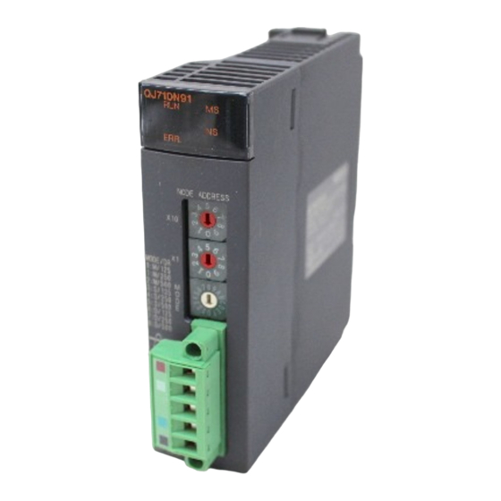
4 SETUP AND PROCEDURES BEFORE OPERATION MELSEC-Q 4.3 Component Names and Settings The following section describes the component names of the QJ71DN91, the meanings of the LED displays, and the setting procedure of the switches. QJ71DN91 ERR. NODE ADDRESS Node number... -
Page 73: Meanings Of The Led Displays
The following explains the names and meanings of the LEDs located on the top surface of the QJ71DN91 when the mode is set to 0 to 8. For the meanings of the LEDs when the mode is set to 9 to C, see Section 4.4, "Hardware Test"... -
Page 74: Node Number Setting Switch
4 SETUP AND PROCEDURES BEFORE OPERATION MELSEC-Q 4.3.2 Node number setting switch The following explains the node number setting switch of the QJ71DN91. Table 4.2 Description of the node number setting switch Name Description Node number Sets the node number of the module. (Setting at the time of shipment from the factory:... -
Page 75: Hardware Test
062F Normal completion (Illuminates the MS LED in green and stores "FFFF" at buffer memory 062E [LED display] Normal completion Performing hardware QJ71DN91 Illuminates the MS LED in green. Flashes the test MS LED. Turns OFF the ERR. LED. QJ71DN91 ERR. -
Page 76: Connecting The Communication Cables To The Qj71Dn91
Shield (drain wire) CAN_L (blue) V- (black) The figure above shows the QJ71DN91's DeviceNet connectors. A sticker in the corresponding cable color is pasted on each connector. Connect the communication cables by making sure that the colors of the connector and cable match. -
Page 77: Communication Test
4 SETUP AND PROCEDURES BEFORE OPERATION MELSEC-Q 4.6 Communication Test The transmission test and reception test are performed by connecting the QJ71DN91 and other DeviceNet devices with a communication cable. There is no restriction on the node number setting of the communication counterpart. -
Page 78: Instructions For Connecting The Network Power Supply
4 SETUP AND PROCEDURES BEFORE OPERATION MELSEC-Q 4.7 Instructions for Connecting the Network Power Supply This section explains the instructions for connecting the network power supply. 4.7.1 Network power supply unit installation position Follow the procedure below to determine the position to install the network power supply unit. -
Page 79: Calculating Network Power Supply Unit Installation Position And Current Capacity
4 SETUP AND PROCEDURES BEFORE OPERATION MELSEC-Q 4.7.2 Calculating network power supply unit installation position and current capacity This section explains the calculating network power supply unit installation position and current capacity. Network power supply unit connected to an end of the network The current capacity is calculated as shown below when the network power supply unit is connected to the end of a thick-cable network with a total length of 200 m. - Page 80 4 SETUP AND PROCEDURES BEFORE OPERATION MELSEC-Q Remedy for insufficient network power supply current capacity If the network power supply unit is connected to a thick-cable network, as shown below. Network power supply unit Termination Termination resistance resistance Master station Slave station Slave station Slave station...
- Page 81 4 SETUP AND PROCEDURES BEFORE OPERATION MELSEC-Q Mixed trunk line and drop line The current capacity is calculated as shown below when the network power supply unit is connected to a network with 200 m of thick-cable trunk line and 6 m of thin-cable drop line.
-
Page 82: Parameter Settings
The parameters 2) through 9) can be set for a maximum of 63 modules. When configuring a DeviceNet network that uses a QJ71DN91 as the master node, it is necessary to set the node number (MAC ID) for the QJ71DN91 and each of the slave nodes. -
Page 83: Parameters For The Slave Function
5 PARAMETER SETTINGS MELSEC-Q 5.1.2 Parameters for the slave function The following explains the setting items of the parameters for the slave function. Description of the parameter settings using the sequence program The parameter settings using the sequence program include the following items: Setting area of the number of slave function reception bytes Setting area of the number of slave function transmission bytes For the method and details of the parameter settings using the sequence... -
Page 84: Setting Using The Auto Configuration Function
5 PARAMETER SETTINGS MELSEC-Q 5.3 Setting Using the Auto Configuration Function The Auto Configuration function automatically creates parameters by detecting a slave node in a DeviceNet network, which is a supplementary function for creating parameters. The Auto Configuration function can reduce the load on the sequence program for parameter settings. - Page 85 5 PARAMETER SETTINGS MELSEC-Q Description of auto configuration settings Table 5.1 lists the items that are automatically detected and set with the Auto Configuration function. To change the contents of settings, use the sequence program. Table 5.1 Items set by auto configuration (1/3) Buffer memory address Item Description...
- Page 86 5 PARAMETER SETTINGS MELSEC-Q Table 5.1 Items set by auto configuration (2/3) Buffer memory address Item Description (hexadecimal) 0210 to 0217 8th node setting Same as the 1st node 0218 to 021F 9th node setting Same as the 1st node 0220 to 0227 10th node setting...
- Page 87 5 PARAMETER SETTINGS MELSEC-Q Table 5.1 Items set by auto configuration (3/3) Buffer memory address Item Description (hexadecimal) 0388 to 038F 55th node setting Same as the 1st node 0390 to 0397 56th node setting Same as the 1st node 0398 to 039F 57th node setting...
-
Page 88: Utility Package (Gx Configurator-Dn)
• Slave Function Transmit Data The values stored in the QJ71DN91's buffer memory for which auto refresh has been set will automatically be read when the END instruction of the PLC CPU is executed. Monitors/tests the buffer memory and I/O signals of the QJ71DN91. In addition, auto configuration and parameter backup can be performed. -
Page 89: Installing And Uninstalling The Utility Package
6 UTILITY PACKAGE (GX Configurator-DN) MELSEC-Q 6.2 Installing and Uninstalling the Utility Package See "Method of installing the MELSOFT Series" attached with the utility package regarding the install and uninstall operation for the utility package. 6.2.1 User precautions The following explains the precautions on using the GX Configurator-DN. Important safety information Since GX Configurator-DN is add-in software for GX Developer, read "Safety Precautions"... - Page 90 The number of parameter settings that can be set for one module in the GX Configurator-DN is as shown below. Object Module Initial setting Automatic refresh setting QJ71DN91 0 (Not used) 18 (Maximum number of settings) Example) Counting the number of parameter settings in the automatic refresh setting The number of settings in this one line is counted as one setting.
-
Page 91: Operating Environment
6 UTILITY PACKAGE (GX Configurator-DN) MELSEC-Q 6.2.2 Operating environment The operating environment of the personal computer where the GX Configurator-DN is used is explained. Item Peripheral devices Installation (Add-in) destination Add-in to GX Developer Version4 (English language version) or later ®... -
Page 92: Explanation Of Utility Package Operation
6 UTILITY PACKAGE (GX Configurator-DN) MELSEC-Q 6.3 Explanation of Utility Package Operation 6.3.1 How to perform common utility package operations Available control keys Special keys that can be used during operation of the utility package and their applications are shown in the table below. Name of key Application Cancels a newly entered value when entering data in a cell. - Page 93 6 UTILITY PACKAGE (GX Configurator-DN) MELSEC-Q Data to be created with the utility package The data and files shown below that are created with the utility package are also processed using GX Developer operation. Figure 6.1 shows which operation processes which data or file. <Intelligent function module parameter>...
- Page 94 The text files can be saved in a desired directory. GX Developer/ Disk GX Configurator-DN Project Project Personal computer QCPU QJ71DN91 QJ71DN91 Q25HCPU MODE ERR. ERR. USER NODE ADDRESS A: Indicates intelligent function module parameter BOOT B: Indicates flash ROM data.
-
Page 95: Overview Of Operation
6 UTILITY PACKAGE (GX Configurator-DN) MELSEC-Q 6.3.2 Overview of operation GX Developer screen [Tools] - [Intelligent function utility] - [Start] Screen for intelligent function module parameter setting module select Enter "Start I/O No.," then select "Package name" and "Module model name." See Section 6.3.3. - Page 96 6 UTILITY PACKAGE (GX Configurator-DN) MELSEC-Q [Tools] - [Flash ROM setting] [Online] - [Monitor/test] Flash ROM settings screen Select monitor/test module Select "Package name" Select and "Module model name." Enter "Start I/O No.," then select "Package name" Monitor/test and "Module model name." Flash ROM settings screen Monitor/Test screen See Section 6.6.
-
Page 97: Starting The Intelligent Function Module Utility
By starting the intelligent function module utility from the GX Developer, display the Parameter Setting Module Selection screen. From this screen, the screens used to perform auto refresh and monitor/test module selection (selecting the module for which monitoring/testing is to be performed) of the QJ71DN91 can be started. [Startup procedure] [Tools]... - Page 98 [Specify Connection Destination]. Use [Read from PC] or [Write to PC] of the GX Developer when mounting the QJ71DN91 to a remote I/O node. Checking for the required utility The head I/O is displayed in the Intelligent function module utility setting screen, but a "...
-
Page 99: Auto Refresh Settings
MELSEC-Q 6.4 Auto Refresh Settings [Purpose of Setting] Sets the QJ71DN91's buffer memory that is automatically refreshed. For the auto refresh setting items, see Section 6.1. Reading and writing with the sequence program will no longer be required by setting auto refresh. - Page 100 6 UTILITY PACKAGE (GX Configurator-DN) MELSEC-Q [Explanation of items] Description of the screen display Buffer size on module side : Displays the buffer memory size of the setting item. Number of transfer words on module side : Displays the number of words to be transferred. Transfer direction : "...
-
Page 101: Monitor/Test
6 UTILITY PACKAGE (GX Configurator-DN) MELSEC-Q 6.5 Monitor/Test [Purpose of Setting] Buffer memory monitoring/testing and I/O signal monitoring/testing are started from this screen. [Startup procedure] Select monitor/test module screen "Start I/O No. " "Package name" "Module model name" Monitor/test The screen can also be started from the GX Developer Version 6 or later system monitor. - Page 102 6 UTILITY PACKAGE (GX Configurator-DN) MELSEC-Q Each Node Obstacle Each Node Configuration Status Monitor Status Monitor Each Node Communication Down Node Detection Status Monitor Disable Status 6 - 15 6 - 15...
- Page 103 6 UTILITY PACKAGE (GX Configurator-DN) MELSEC-Q Message Communication Master Function Receive Area Monitor/Test Data Monitor Master Function For IO Master Function Transmit Address Area Monitor Data Monitor/Test 6 - 16 6 - 16...
- Page 104 6 UTILITY PACKAGE (GX Configurator-DN) MELSEC-Q Slave Function Receive Auto Configuration Data Monitor Slave Function Transmit Flash ROM Clear Data Monitor/Test 6 - 17 6 - 17...
- Page 105 6 UTILITY PACKAGE (GX Configurator-DN) MELSEC-Q Parameter Backup Parameters saved in a file can be edited with "Flash ROM setting". 6 - 18 6 - 18...
- Page 106 "Down Node Detection Inhibit Settings". Change the setting value field from "1 node" to "Do not detect". Nothing is written to the QJ71DN91 at this point. Click the setting value field showing "1 node" to select. To write more than one setting item at the same time, select multiple items while holding down the Ctrl key.
-
Page 107: Flash Rom Settings
6 UTILITY PACKAGE (GX Configurator-DN) MELSEC-Q 6.6 Flash ROM Settings [Purpose of Setting] The contents of flash ROM settings are edited offline. The edited parameters can be written into the module on the "Parameter Backup" screen of "Monitor/Test". [Startup procedure] Flash ROM Setting screen "Package name"... - Page 108 6 UTILITY PACKAGE (GX Configurator-DN) MELSEC-Q [Explanation of items] Description of screen display Setting item : Displays the parameter names. Setting (value) : Enter or select the value to be set in the flash ROM. Explanation of the command buttons File save Saves the parameters in the hard disk, etc.
-
Page 109: Programming When Executing The Master Function
7 PROGRAMMING WHEN EXECUTING THE MASTER FUNCTION MELSEC-Q 7 PROGRAMMING WHEN EXECUTING THE MASTER FUNCTION This chapter explains programming when the master function is executed. 7.1 Precautions on Programming This section explains the precautions when creating a program. (1) Observe the following to perform input/output communication with a slave node. •... - Page 110 D500, then stores the node number of the error causing node into D501 and the error code into D502 separately. 6) The attribute data for message communication write is set in D30. 7) It is assumed that the QJ71DN91 (master node) is mounted in slot 0 of the basic base. Q61P Q25H...
- Page 111 8-point input Reception data FROM I00 to I07 X100 to X107 Node No. 1 reception Input 00 to input 07 QJ71DN91 slave node (node No. 4) Node No. 4 FROM X110 to X14F reception 8-byte transmission/reception Node No. 3 status...
-
Page 112: Setting Parameters
7 PROGRAMMING WHEN EXECUTING THE MASTER FUNCTION MELSEC-Q 7.3 Setting Parameters This section explains examples of program for setting parameters. If GX Configurator-DN is used, the programs described in Section 7.3.1 through Section 7.3.3 will not be required. 7.3.1 Parameter settings using the sequence program The following shows a method for setting parameters using the sequence program. - Page 113 7 PROGRAMMING WHEN EXECUTING THE MASTER FUNCTION MELSEC-Q Command for setting the parameters for the master function Sets the node number of the third slave node to 4 and the message group to 3. Sets the connection type of the third slave node to polling.
-
Page 114: Creating Parameters Using Auto Configuration
7 PROGRAMMING WHEN EXECUTING THE MASTER FUNCTION MELSEC-Q 7.3.2 Creating parameters using auto configuration The following explains a method for creating parameters using auto configuration. Auto configuration command All configuration Auto configuration Maximum detection station number = 4 command Auto configuration request Checks auto configuration in progress. -
Page 115: I/O Communication With Slave Nodes
7 PROGRAMMING WHEN EXECUTING THE MASTER FUNCTION MELSEC-Q 7.4 I/O Communication with Slave Nodes This section explains an example of a sequence program that performs I/O communication. If GX Configurator-DN is used, the FROM and TO instructions are not required. Parameter setting program Parameter setting program (See Section 7.3.) -
Page 116: Performing Message Communication
7 PROGRAMMING WHEN EXECUTING THE MASTER FUNCTION MELSEC-Q 7.5 Performing Message Communication This section explains an example of a sequence program that performs message communication. 7.5.1 Example of message communication read The following shows an example of a sequence program that reads attributes from node number 3. -
Page 117: Example Of Message Communication Write
7 PROGRAMMING WHEN EXECUTING THE MASTER FUNCTION MELSEC-Q 7.5.2 Example of message communication write The following shows an example of a sequence program that writes attributes to node number 3. In sections enclosed with a dashed line, the area that is actually read and written as well as the class ID, instance ID and attribute ID are different depending on the slave node. -
Page 118: Obtaining Error Information
7 PROGRAMMING WHEN EXECUTING THE MASTER FUNCTION MELSEC-Q 7.6 Obtaining Error Information This section explains an example of a sequence program that obtains the error information for the master function. Reads the error code from the buffer memory. Number of station in which an error has occurred Error information Error code... -
Page 119: Allocating Transmission/Reception Data Storage Devices For Future Expansion
FROM and TO instructions are executed while using the read and write starting addresses of the buffer memory of this information and the data length. PLC CPU QJ71DN91 master station Remote I/O (station No. 1) 8-point input Reception data... - Page 120 7 PROGRAMMING WHEN EXECUTING THE MASTER FUNCTION MELSEC-Q The following explains an example of the sequence program used in this case. Parameter setting program Parameter setting program (See Section 7.3.) I/O communication start command Starts I/O communication. Reads the I/O address area information.
-
Page 121: Programming When Executing The Slave Function
Y200 to Y27F. 2) If an error occurs, the error information is read to D500. 3) It is assumed that the QJ71DN91 (slave node) is mounted in slot 0 of the basic base. 8 - 1... -
Page 122: Setting Parameters Using The Sequence Program
8 PROGRAMMING WHEN EXECUTING THE SLAVE FUNCTION MELSEC-Q 8.2 Setting Parameters Using the Sequence Program This section explains an example of a sequence program for setting parameters. Command for setting parameters for the slave function Sets the number of reception bytes to 16 bytes. -
Page 123: I/O Communication With The Master Node
8 PROGRAMMING WHEN EXECUTING THE SLAVE FUNCTION MELSEC-Q 8.3 I/O Communication with the Master Node This section explains an example of a sequence program that performs I/O communication with the master node. Parameter setting program Parameter setting program (See Section 8.2.) I/O communication start command Sets the initial setting value of... -
Page 124: Obtaining Error Information
8 PROGRAMMING WHEN EXECUTING THE SLAVE FUNCTION MELSEC-Q 8.4 Obtaining Error Information This section explains an example of a sequence program that obtains the error information for the slave function. Reads the error code from the buffer memory. Error handling program Error reset Sets the error reset request. -
Page 125: Troubleshooting
9 TROUBLESHOOTING MELSEC-Q 9 TROUBLESHOOTING This chapter explains the contents of errors that may occur while using the QJ71DN91 as well as their troubleshooting procedures. This chapter consists of the following two sections: Section 9.1 Items to Check When an Error Occurs Shows troubleshooting procedures based on the phenomenon of errors. -
Page 126: Checking The Leds
9 TROUBLESHOOTING MELSEC-Q 9.1 Items to Check When an Error Occurs This section explains the items to check when an error occurs and its troubleshooting procedure: 9.1.1 Checking the LEDs Occurrence of an error Reset by setting the mode switch between Is the mode switch set between 0 and 8? 0 and 8. -
Page 127: When Communication With All Slave Nodes Cannot Be Performed (Using The Master Function)
0 and 2 or between 6 and 8? 0 and 2 or between 6 and 8. Is the communication cable securely Connect the communication cable securely. connected to the QJ71DN91 connector? Turn ON the network power. Is the network power turned ON? Is the communication speed... -
Page 128: When Communication With A Specific Slave Node Cannot Be Performed (Using The Master Function)
9 TROUBLESHOOTING MELSEC-Q 9.1.3 When communication with a specific slave node cannot be performed (using the master function) Communication with a specific slave node cannot be performed (when the NS LED is flashing in red) Turn ON the slave node power. Is the slave node power turned ON? Is the communication cable securely Connect the communication cable securely. -
Page 129: When Communication With The Master Node Cannot Be Performed (Using The Slave Function)
Reset by setting the mode switch between 3 and 8. Is the communication cable securely Connect the communication cable securely. connected to the QJ71DN91 connector? Is the network power turned ON? Turn ON the network power. Set the same communication speed in all... -
Page 130: Error Codes
The value of the local node number (MAC ID) is • Set the local node number between 0 and 63. QJ71DN91 out of range. • Set the mode switch to other than D and E. The value of the mode switch is out of range. - Page 131 Master Slave code function function QJ71DN91 No slave node has been set. • Set at least one slave node. The total input data length of all slave nodes is • Reduce the total input data length of all slave QJ71DN91 too long.
- Page 132 • Check the slave node manual, and change the setting so that any data of functions not supported by the QJ71DN91 will not be sent by Response data of a function that is not supported the slave node.
-
Page 133: Execution Error Codes Of Message Communication (Using The Master Function Only)
• Check the entire network and slave node statuses such as QJ71DN91 Slave node did not respond. whether or not a slave node is down or a terminal resistor is disconnected. - Page 134 QJ71DN91 The sequence of the division reception is invalid. whether or not a terminal resistor is disconnected. QJ71DN91 The data length set in the buffer memory is 241 or more. • Set the data length to 240 bytes or less.
-
Page 135: Verifying The Qj71Dn91 Status On The Gx Developer System Monitor
9 TROUBLESHOOTING MELSEC-Q 9.3 Verifying the QJ71DN91 Status on the GX Developer System Monitor When the QJ71DN91 detailed information is selected on the GX Developer system monitor, the error codes and LED illumination status can be verified. (a) Setting procedure Select the module by clicking "Diagnostics"... - Page 136 9 TROUBLESHOOTING MELSEC-Q (c) H/W LED Information Displays the LED illumination status of the QJ71DN91. (0: off, 1: on) ERR: Indicates the "ERR" LED on status. MS RED: Indicates the "MS red" LED on status. MS GREEN: Indicates the "MS green" LED on status.
-
Page 137: Appendix
APPENDIX MELSEC-Q APPENDIX Appendix 1 External Dimension Diagram The following figure shows an external dimension diagram of the QJ71DN91: QJ71DN91 ERR. NODE ADDRESS MODE/DR 0 : M/125 1 : M/250 2 : M/500 3 : S/125 4 : S/250 5 : S/500... -
Page 138: Appendix 2 Differences Between The Qj71Dn91 And The Aj71Dn91/A1Sj71Dn91
APPENDIX MELSEC-Q Appendix 2 Differences between the QJ71DN91 and the AJ71DN91/A1SJ71DN91 The following table lists the differences between the QJ71DN91 and the AJ71DN91/A1SJ71DN91: Model name QJ71DN91 AJ71DN91/A1SJ71DN91 Function DeviceNet master function and DeviceNet DeviceNet master/slave function DeviceNet master function only... -
Page 139: Appendix 3 Parameter Setting Sheet (For The Master Function)
APPENDIX MELSEC-Q Appendix 3 Parameter Setting Sheet (For the Master Function) Buffer memory Item Setting range Remark Setting value address Constant scan 0 ms to 65535 ms 01D7 Setting to make the link scan time constant. Buffer memory Item Setting range Remark Setting value address... -
Page 140: Appendix 4 Parameter Setting Sheet (For The Slave Function)
APPENDIX MELSEC-Q Appendix 4 Parameter Setting Sheet (For the Slave Function) Buffer memory Item Setting range Remark Setting value address Setting area for the number of slave 0 to 128 bytes 060E Sets the I/O data reception size for the slave function parameters. function input points Setting area for the number of slave... -
Page 141: Appendix 5 List Of Communication Parameters Of Slave Nodes Manufactured By Various Manufacturers
UCMM manufacturer name type Timeout group Rate Time Output Input Output Input Output Input Action DeviceNet 200ms Timeout QJ71DN91 master/slave Polling (H1) (K201) (H1) (H0) Mitsubishi module Electric A500 Series Corporation inverter 1000ms Timeout 10ms FR-A5ND Polling (H1) DeviceNet (K1001) -
Page 142: Appendix 6 Eds File Of The Qj71Dn91
APPENDIX MELSEC-Q Appendix 6 EDS File of the QJ71DN91 The following shows the EDS file of the QJ71DN91. The EDS file is stored in the CD- ROM of GX Configurator-DN. $ Mitsubishi Master/Slave EDS file $ File Description Section [File] DescText="QJ71DN91 EDS file";... - Page 143 APPENDIX MELSEC-Q MEMO App - 7 App - 7...
-
Page 144: Index
Master function (I/O communication function) 3-2 Master function communication status..3-32 DeviceNet general error code list ....3-31 Master function for IO address area....3-40 Differences between the QJ71DN91 and the Master function for error Information.....3-33 AJ71DN91/A1SJ71DN91......App-2 Master function for error set signal....3-18 Down node detection disable status..... - Page 145 Watchdog timer error ........3-14 Ind. Model name display ........3-43 Module ready..........3-22 Obtaining error information (master function) ........... 7-10 Obtaining error information (slave function) ... 8-4 ODVA............... 2-2 Parameter save area selection bit ....3-45 Parameters for the master function ..... 3-35 Performance specifications......
- Page 146 1. Gratis Warranty Term and Gratis Warranty Range If any faults or defects (hereinafter "Failure") found to be the responsibility of Mitsubishi occurs during use of the product within the gratis warranty term, the product shall be repaired at no cost via the dealer or Mitsubishi Service Company.
- Page 147 Microsoft Windows, Microsoft Windows NT are registered trademarks of Microsoft Corporation in the United States and other countries. Pentium is a registered trademark of Intel Corporation in the United States and other countries. Other company and product names herein are either trademarks or registered trademarks of their respective owners.
- Page 148 DeviceNet Master-Slave Module User's Manual QJ71DN91-U-S-E MODEL MODEL 13JR32 CODE SH(NA)-080143-C(0202)MEE HEAD OFFICE : 1-8-12, OFFICE TOWER Z 14F HARUMI CHUO-KU 104-6212,JAPAN NAGOYA WORKS : 1-14 , YADA-MINAMI 5 , HIGASHI-KU, NAGOYA , JAPAN When exported from Japan, this manual does not require application to the Ministry of Economy, Trade and Industry for service transaction permission.
Need help?
Do you have a question about the QJ71DN91 and is the answer not in the manual?
Questions and answers