Advertisement
Quick Links
Please dispose of packaging for the product in a responsible
Variable Speed
manner. It is suitable for recycling. Help to protect the
environment, take the packaging to the local amenity tip
and place into the appropriate recycling bin.
Drill Press
Never dispose of electrical equipment or batteries in with
your domestic waste. If your supplier offers a disposal facili-
ty please use it or alternatively use a recognised re-cycling
agent. This will allow the recycling of raw materials and help
protect the environment.
FOR HELP OR ADVICE ON THIS PRODUCT PLEASE CONTACT YOUR DISTRIBUTOR,
OR SIP DIRECTLY ON:
TEL: 01509500400
01533 & 01535
EMAIL: sales@sip-group.com or technical@sip-group.com
www.sip-group.com
Please read and fully understand the instructions in
this manual before operation. Keep this manual
Ref: 190117
safe for future reference
1
28
Advertisement

Related Manuals for SIP 01533


Summary of Contents for SIP 01533
-
Page 1: Drill Press
This will allow the recycling of raw materials and help protect the environment. FOR HELP OR ADVICE ON THIS PRODUCT PLEASE CONTACT YOUR DISTRIBUTOR, OR SIP DIRECTLY ON: TEL: 01509500400 01533 & 01535 EMAIL: sales@sip-group.com or technical@sip-group.com www.sip-group.com... -
Page 2: Declaration Of Conformity
As the manufacturer's authorised representative within the EC declare that the Variable Speed Drill Press (Bench) - SIP Part. No. 01533 Variable Speed Drill Press (Floor) - SIP Part. No. 01535 Conforms to the requirements of the following directive(s), as indicated. - Page 3 NOTES CONTENTS Ref. No. Description SIP Part No. Ref. No. Description SIP Part No. 117. Retaining ring WK06-00113 126. Screw WK06-00122 118. Screw WK06-00114 127. Washer WK06-00123 Page No. Description 119. Spindle fixed pulley WK06-00115 128. Screw WK06-00124 120. Spindle movable...
- Page 4 SAFETY SYMBOLS USED THROUGHOUT THIS MANUAL PARTS LIST….cont Ref. No. Description SIP Part No. Ref. No. Description SIP Part No. Danger / Caution: Indicates risk of personal injury and/or the possibility of damage. Retaining ring WK06-00058 Spring WK06-00085 Retaining ring...
- Page 5 PARTS LIST SAFETY INSTRUCTIONS….cont work area. Do not use in environments with a potentially explosive atmosphere. Ref. No. Description SIP Part No. Ref. No. Description SIP Part No. KEEP CHILDREN AND UNTRAINED PERSONNEL AWAY FROM THE WORK AREA: All visitors...
- Page 6 USE ONLY RECOMMENDED ACCESSORIES: Consult this user manual, your distributor or SIP directly for recommended accessories. Follow the instructions that accompany the accessories. The use of improper accessories may cause hazards and will invali- date any warranty you may have.
- Page 7 MAINTENANCE INSTRUCTIONS….cont SAFETY INSTRUCTIONS….cont Secure the base of the drill to a work bench or the floor before using the drill Fitting the new belt: press. If the work is heavy or large and likely to cause the drill to tip over, use additional supports as appropriate under and around the work-piece.
- Page 8 TECHNICAL SPECIFICATIONS MAINTENANCE INSTRUCTIONS….cont CHANGING THE DRIVE BELT Over time the belt can become loose or worn and will need to be replaced. Part number 01533 01535 Input voltage 230v ~ 50hz 230v ~ 50hz Drive Belt Screw Power 550 w...
- Page 9 Over time the tension of the spindle may need to be adjusted. These SIP drills are fitted with a standard 230v ~ 13 amp type plug. Before using the drill, inspect the mains lead and plug to ensure that neither are damaged. If any Caution: Take care when you remove the grub screw;...
- Page 10 Scale Pointer This SIP variable speed drill press is covered by a 12 month parts and labour warranty covering failure due to manufacturers defects. This does not cover failure due to mis- use or operating the drill press outside the scope of this manual - any claims deemed to be outside the scope of the warranty may be subject to charges Including, but not limited to parts, labour and carriage costs.
- Page 11 OPERATING INSTRUCTIONS….cont GETTING TO KNOW YOUR DRILL TABLE ADJUSTMENTS To adjust the height of the table: Loosen the table height lock (turn anti-clockwise). Rotate the table height adjust and the table will rise / fall along the rack. Tighten the table height lock (turn clockwise) to secure the table at the desired height.
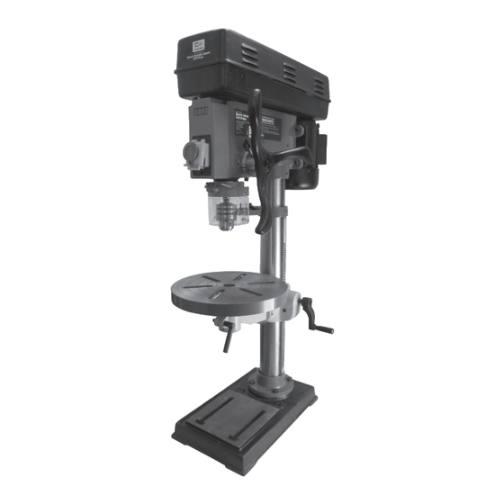
- Page 12 Column Chuck Guard Your SIP drill press is fitted with a safety NVR (No Volt Release) switch. This means that if Tool Tray On/Off (NVR) Switch power is cut to the drill (such as in a power failure); the motor will not start to run once...
- Page 13 ASSEMBLY INSTRUCTIONS….cont ASSEMBLY INSTRUCTIONS….cont Ensure that the inside of the chuck and the outside of the arbor are free from dust or debris etc. Push the chuck up over the arbor. Fit the rack into the pinion assembly and slide both Tap into place with a mallet or a scrap the table support and the rack over the column as piece of wood.
- Page 14 ASSEMBLY INSTRUCTIONS….cont ASSEMBLY INSTRUCTIONS….cont FIT THE SPINDLE HAND-WHEEL Fit the table onto the table support arm. Fit the depth stop collar over the spindle hand-wheel Secure in place with the Table Orientation Lock. (as shown). Table Orientation Lock Note: Put a small amount of grease between the collar and hand-wheel shaft to allow them to move more freely.
Need help?
Do you have a question about the 01533 and is the answer not in the manual?
Questions and answers