Table of Contents
Advertisement
Quick Links
Advertisement
Table of Contents

Related Manuals for Asus STRIX H270F GAMING


Summary of Contents for Asus STRIX H270F GAMING
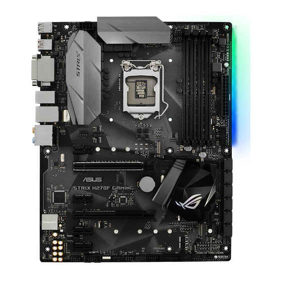
- Page 1 STRIX H270F GAMING...
- Page 2 Product warranty or service will not be extended if: (1) the product is repaired, modified or altered, unless such repair, modification of alteration is authorized in writing by ASUS; or (2) the serial number of the product is defaced or missing.
-
Page 3: Table Of Contents
Contents Safety information ....................... v About this guide ......................vi STRIX H270F GAMING specifications summary ........... viii Package contents ...................... xii Installation tools and components ................. xiii Chapter 1: Product Introduction Motherboard overview ................1-1 1.1.1 Before you proceed ..............1-1 1.1.2... - Page 4 Ai Tweaker menu ..................3-13 Advanced menu ..................3-19 Monitor menu ................... 3-26 Boot menu ....................3-31 Tool menu ....................3-35 3.9.1 ASUS EZ Flash 3 Utility ............3-35 3.9.2 Secure Erase ................3-36 3.9.3 Setup Animator ................. 3-37 3.9.4 ASUS Overclocking Profile ............
-
Page 5: Safety Information
Safety information Electrical safety • To prevent electrical shock hazard, disconnect the power cable from the electrical outlet before relocating the system. • When adding or removing devices to or from the system, ensure that the power cables for the devices are unplugged before the signal cables are connected. If possible, disconnect all power cables from the existing system before you add a device. -
Page 6: About This Guide
Refer to the following sources for additional information and for product and software updates. ASUS website The ASUS website (www.asus.com) provides updated information on ASUS hardware and software products. Optional documentation Your product package may include optional documentation, such as warranty flyers, that may have been added by your dealer. -
Page 7: Conventions Used In This Guide
Conventions used in this guide To ensure that you perform certain tasks properly, take note of the following symbols used throughout this manual. DANGER/WARNING: Information to prevent injury to yourself when trying to complete a task. CAUTION: Information to prevent damage to the components when trying to complete a task. -
Page 8: Strix H270F Gaming Specifications Summary
Optane Technology in only supported when using 7th Generation Intel® ® Processors. ** Refer to www.asus.com for the lastest Memory QVL(Qualified Vendors List). 1 x PCIe 3.0/2.0 x16 slot (at x 16 mode) 1 x PCI Express 3.0/2.0 x16 slot (max. at x4 mode) Expansion slots 4 x PCIe 3.0/2.0 x1 slots... - Page 9 Audio Features - Sonic Radar III - Sonic Studio III ASMedia USB 3.1 controllers - supports ASUS USB 3.1 Boost - 2 x USB 3.1 ports (1 x Type-A [red] and 1 x Type-C ports at back panel) Intel H270 Chipset ®...
- Page 10 STRIX H270F GAMING specifications summary Gamers Guardian - SafeSlot - DIGI+ VRM - DRAM Overcurrent Protection - ESD Guards on LAN, Audio, KBMS and USB3.0/2.0 ports - Highly Durable Components - Stainless Steel Back I/O ASUS EZ DIY - ASUS EZ Flash 3...
- Page 11 STRIX H270F GAMING specifications summary 128 Mb Flash ROM, UEFI AMI BIOS, PnP, DMI3.0, WfM2.0, SM BIOS 3.0, ACPI 6.0, Multi-language BIOS, ASUS EZ Flash 3, CrashFree BIOS 3, F11 EZ Tuning Wizard, F6 Qfan Control, F3 My Favorites, Quick Note, Last...
-
Page 12: Package Contents
Package contents Check your motherboard package for the following items. Motherboard STRIX H270F GAMING 2 x 2-in-1 SATA 6Gb/s cables Cables 1 x RGB LED extension cable 1 x I/O shield 1 x ROG SATA cable label 1 x ROG Strix sticker... -
Page 13: Installation Tools And Components
Installation tools and components Intel 1151 CPU ® Intel 1151 compatible CPU Fan ® Phillips (cross) screwdriver SATA hard disk drive PC chassis 1 bag of screws DIMM Power supply unit SATA optical disc drive (optional) Graphics card The tools and components listed above are not included in the motherboard package. xiii... -
Page 15: Chapter 1: Product Introduction
Unplug the power cord from the wall socket before touching any component. • Before handling components, use a grounded wrist strap or touch a safely grounded object or a metal object, such as the power supply case, to avoid damaging them due to static electricity. • Hold components by the edges to avoid touching the ICs on them. • Whenever you uninstall any component, place it on a grounded antistatic pad or in the bag that came with the component. • Before you install or remove any component, ensure that the ATX power supply is switched off or the power cord is detached from the power supply. Failure to do so may cause severe damage to the motherboard, peripherals, or components. ASUS STRIX H270F GAMING... -
Page 16: Motherboard Layout
MOUNT LGA1151 KBMS_USB78 LAN_USB3_56 CHA_FAN1 AIO_PUMP AUDIO 2280 2260 2242 PCIEX1_1 PCIE SATA IRST PCIEX16_1 Intel I219V Intel ® BATTERY strix H270F GAMING H270 Super PCIEX1_2 128Mb BIOS PCIEX16_2 1220 COVER 22110 2280 2260 2242 PCIEX1_3 MOUNT SB_PWR PCIEX1_4 USB3_34... -
Page 17: Layout Contents
9. USB 3.0 connectors (20-1 pin USB3_12, USB3_34) 1-14 10. Intel Serial ATA 6 Gb/s connectors (7-pin SATA6G_1~6) 1-13 ® 11. Standby power LED (SB_PWR) 1-11 12. Clear RTC RAM jumper (2-pin CLRTC) 13. System panel connector (20-5 pin PANEL) 1-18 14. Thermal sensor cable connector (2-pin T_SENSOR) 1-20 15. USB 2.0 connectors (10-1 pin USB1112, USB1314) 1-15 16. ROG Extension connector (18-1 pin ROG_EXT) 1-15 17. TPM connector (14-1 pin TPM) 1-19 18. RGB header (4-pin RGB_HEADER) 1-21 19. Serial port connector (10-1 pin COM) 1-19 20. Front panel audio connector (10-1 pin AAFP) 1-14 ASUS STRIX H270F GAMING... -
Page 18: Central Processing Unit (Cpu)
1.1.3 Central Processing Unit (CPU) The motherboard comes with a surface mount LGA1151 socket designed for the 7th / 6th Generation Intel Core™ i7 / Intel Core™ i5 / Intel Core™ i3, Pentium , and Celeron ® ® ® ® ® processors. strix H270F GAMING STRIX H270F GAMING CPU socket LGA1151 • Ensure that all power cables are unplugged before installing the CPU. • Upon purchase of the motherboard, ensure that the PnP cap is on the socket and the socket contacts are not bent. Contact your retailer immediately if the PnP cap is missing, or if you see any damage to the PnP cap/socket contacts/motherboard components. ASUS will shoulder the cost of repair only if the damage is shipment/ transit-related. • Keep the cap after installing the motherboard. ASUS will process Return Merchandise Authorization (RMA) requests only if the motherboard comes with the cap on the LGA1151 socket. • The product warranty does not cover damage to the socket contacts resulting from incorrect CPU installation/removal, or misplacement/loss/incorrect removal of the PnP cap. -
Page 19: System Memory
1.1.4 System memory The motherboard comes with four DDR4 (Double Data Rate 4) Quad Inline Memory Modules (DIMM) slots. A DDR4 module is notched differently from a DDR, DDR2, or DDR3 module. DO NOT install a DDR, DDR2, or DDR3 memory module to the DDR4 slot. strix H270F GAMING STRIX H270F GAMING 288-pin DDR4 DIMM sockets Recommended memory configurations ASUS STRIX H270F GAMING... -
Page 20: Memory Configurations
Install a 64-bit Windows OS when you want to install 4 GB or more on the ® motherboard. c) For more details, refer to the Microsoft support site at http://support.microsoft. ® com/kb/929605/en-us. • The design of the DIMM fan may vary. Ensure that the DIMM fan fits to the motherboard • The default memory operation frequency is dependent on its Serial Presence Detect (SPD), which is the standard way of accessing information from a memory module. Under the default state, some memory modules for overclocking may operate at a lower frequency than the vendor-marked value. • For system stability, use a more efficient memory cooling system to support a full memory load (4 DIMMs) or overclocking condition. • Always install the DIMMS with the same CAS Latency. For an optimum compatibility, we recommend that you install memory modules of the same version or data code (D/C) from the same vendor. Check with the vendor to get the correct memory modules. • ASUS exclusively provides hyper DIMM support function. • Hyper DIMM support is subject to the physical characteristics of individual CPUs. Load the X.M.P. or D.O.C.P. settings in the BIOS for the hyper DIMM support. • Visit the ASUS website for the latest QVL. Chapter 1: Product Introduction... -
Page 21: Expansion Slots
1.1.5 Expansion slots Unplug the power cord before adding or removing expansion cards. Failure to do so may cause you physical injury and damage motherboard components. PCIEX1_1 PCIEX16_1 strix H270F GAMING PCIEX1_2 PCIEX16_2 PCIEX1_3 PCIEX1_4 Slot No. Slot Description PCIE_x1_1 slot PCIE_x16_1 slot PCIE_x1_2 slot PCIE_x16_2 slot PCIE_x1_3 slot PCIE_x1_4 slot ASUS STRIX H270F GAMING... - Page 22 PCI Express 3.0 operating mode VGA configuration PCIe_x16/x8_1 PCIe_x4_2 x16 (single VGA Single VGA/PCIe card recommended) Dual VGA/PCIe card • We recommend that you provide sufficient power when running CrossFireX™ mode. • Connect a chassis fan to the motherboard connector labeled CHA_FAN1-2 when using multiple graphics cards for better thermal environment. IRQ assignments for this motherboard PCIEX1_1 – – – shared PCIEX16_1 shared – – – PCIEX1_2 – – – shared PCIEX16_2 shared –...
-
Page 23: Headers / Holes
1.1.6 Headers / Holes Clear RTC RAM (2-pin CLRTC) This header allows you to clear the CMOS RTC RAM data of the system setup information such as date, time, and system passwords. CLRTC strix H270F GAMING PIN 1 STRIX H270F GAMING Clear RTC RAM To erase the RTC RAM: Turn OFF the computer and unplug the power cord. Use a metal object such as a screwdriver to short the two pins. Plug the power cord and turn ON the computer. Hold down the <Del> key during the boot process and enter BIOS setup to re-enter data. If the steps above do not help, remove the onboard battery and short the two pins again to clear the CMOS RTC RAM data. After clearing the CMOS, reinstall the battery. ASUS STRIX H270F GAMING... -
Page 24: Onboard Leds
3D Mount holes Create a 3D printout and secure it to these 3D Mount holes for a personalized motherboard. 3D Mount strix H270F GAMING 3D Mount STRIX H270F GAMING 3D Printing Mount • Download 3D source files at http://www.asus.com. • Use the bundled 3D mount printing screws to install the 3D printouts. 1.1.7 Onboard LEDs POST State LEDs The POST State LEDs provide the status of these key components during POST (Power-On Self-Test): CPU, memory modules, VGA card, and hard disk drives. If an error is found, the critical component’s LED stays lit up until the problem is solved. BOOT_DEVICE_LED VGA_LED DRAM_LED CPU_LED strix H270F GAMING STRIX B250F GAMING Boot_Device/VGA/DRAM/CPU LED... - Page 25 STRIX H270F GAMING Onboard LED RGB LED The RGB LED lighting control provides several lighting schemes, which allow you to customize your favorite LED effect. You can set your favorite LED effect to cast a stunning multi-color glow across your build, change shades to indicate CPU temperature, pulsate in time to the beat of your music, or set your favorite color for each pair of LEDs. RGB1 RGB2 RGB3 RGB4 RGB5 RGB6 RGB LED(Bottom) RGB7 RGB8 RGB9 RGB10 RGB11 RGB12 strix H270F GAMING STRIX H270F GAMING RGB LED Lighting ASUS STRIX H270F GAMING 1-11...
-
Page 26: Internal Connectors
SATA6G_4 SATA6G_1 strix H270F GAMING RSATA_TXP4 RSATA_TXP1 RSATA_TXN4 RSATA_TXN1 RSATA_RXN4 RSATA_RXN1 RSATA_RXP4 RSATA_RXP1 STRIX H270F GAMING Intel SATA 6.0Gb/s connectors ® • These connectors are set to [AHCI] by default. If you intend to create a Serial ATA RAID set using these connectors, set the SATA Mode item in the BIOS to [Intel RST Premium With Intel Optane System Acceleration (RAID)]. • Before creating a RAID set, refer to the manual bundled in the motherboard support DVD. Chapter 1: Product Introduction 1-12... - Page 27 Front panel audio connector (10-1 pin AAFP) This connector is for a chassis-mounted front panel audio I/O module that supports HD Audio. Connect one end of the front panel audio I/O module cable to this connector. AAFP PIN 1 strix H270F GAMING HD-audio-compliant Legacy AC’97 pin definition compliant definition STRIX H270F GAMING Front panel audio connector We recommend that you connect a high-definition front panel audio module to this connector to avail of the motherboard’s high-definition audio capability. USB 3.0 connectors (20-1 pin USB3_12, USB3_34) These connectors allow you to connect a USB 3.0 module for additional USB 3.0 front or rear panel ports. With an installed USB 3.0 module, you can enjoy all the benefits of USB 3.0 including faster data transfer speeds of up to 5 Gb/s, faster charging time for USB-chargeable devices, optimized power efficiency, and backward compatibility with USB 2.0. USB3_12...
- Page 28 ROG Extension connector (18-1 pin ROG_EXT) This connector is for the OC Panel I/II, Front Base, and other ROG devices. strix H270F GAMING ROG_EXT STRIX H270F GAMING ROG_EXT connectors • The Front Base is purchased separately. • Visit www.asus.com for more information about the OC Panel and Front Base. USB 2.0 connectors (10-1 pin USB1112, USB1314) These connectors are for USB 2.0 ports. Connect the USB module cable to any of these connectors, then install the module to a slot opening at the back of the system chassis. These USB connectors comply with USB 2.0 specification that supports up to 480 Mb/s connection speed. USB1112 USB1314 strix H270F GAMING PIN 1 PIN 1 STRIX H270F GAMING USB2.0 connectors...
- Page 29 Do not place jumper caps on the fan connectors! • Ensure that the CPU fan cable is securely installed to the CPU fan connector. CPU_FAN CPU_OPT AIO_PUMP CHA_FAN1 CHA_FAN2 EXT_FAN strix H270F GAMING PIN 1 STRIX H270F GAMING Fan connectors • The CPU_FAN connector supports the CPU fan of maximum 1A (12 W) fan power. • The EXT_FAN connector supports 2 of 5 thermal sensor sources. • To install more fans, refer to section 2.1.8 Expansion card installation for details. • Connect the fan of your water cooling kit to the CPU_FAN connector. ASUS STRIX H270F GAMING 1-15...
- Page 30 -5 Volts PIN 1 +5 Volts +5 Volts PSON# +3 Volts -12 Volts +3 Volts +3 Volts strix H270F GAMING PIN 1 STRIX H270F GAMING ATX power connectors • For a fully configured system, we recommend that you use a power supply unit (PSU) that complies with ATX 12 V Specification 2.0 (or later version) and provides a minimum power of 350 W. • DO NOT forget to connect the 8-pin EATX12V power plug. Otherwise, the system will not boot. • We recommend that you use a PSU with a higher power output when configuring a system with more power-consuming devices. The system may become unstable or may not boot up if the power is inadequate.
-
Page 31: System Panel Connector
System panel connector (20-5 pin PANEL) This connector supports several chassis-mounted functions. PANEL +PWR_LED- SPEAKER PWR_SW PIN 1 strix H270F GAMING +HDD_LED- RESET +PWR_LED- * Requires an ATX power supply STRIX H270F GAMING System panel connector • System power LED (4-pin +PWR_LED-) This 2-pin connector is for the system power LED. Connect the chassis power LED cable to this connector. The system power LED lights up when you turn on the system power, and blinks when the system is in sleep mode. • Hard disk drive activity LED (2-pin +HDD_LED-) This 2-pin connector is for the HDD Activity LED. Connect the HDD Activity LED cable to this connector. The HDD LED lights up or flashes when data is read from or written to the HDD. •... - Page 32 This connector supports a Trusted Platform Module (TPM) system, which securely stores keys, digital certificates, passwords and data. A TPM system also helps enhance network security, protect digital identities, and ensures platform integrity. PIN 1 strix H270F GAMING STRIX H270F GAMING TPM connector The TPM module is purchased separately. Serial port connector (10-1 pin COM) This connector is for a serial (COM) port. Connect the serial port module cable to this connector, then install the module to a slot opening at the back of the system chassis. PIN 1 strix H270F GAMING STRIX H270F GAMING Serial port (COM) connector The COM module is purchased separately. Chapter 1: Product Introduction 1-18...
- Page 33 STRIX H270F GAMING M.2(SOCKET3)s • M.2_1 socket supports PCIe 3.0 x2 and SATA mode M Key design and type 2242 / 2260 / 2280 PCIe and SATA storage devices. • M.2_2 socket supports PCIe 3.0 x4 M Key design and type 2242 / 2260 / 2280 / 2210 PCIe storage devices. • M.2_2 socket supports IRST (Intel ® Rapid Storage Technology). The M.2 SSD module is purchased separately. Thermal sensor connector (2-pin T_SENSOR) This connector is for the thermistor cable that monitors the temperature of the devices and the critical components inside the motherboard. Connect the thermistor cable and place the sensor on the device or the motherboard’s component to detect its temperature. strix H270F GAMING T_SENSOR PIN 1 SENSOR IN STRIX H270F GAMING T_SENSOR connector ASUS STRIX H270F GAMING 1-19...
- Page 34 RGB headers (4-pin RGB_HEADER) This connector is for RGB LED strips. RGB_HEADER PIN 1 +12V G R B strix H270F GAMING STRIX H270F GAMING RGB_HEADER connector The RGB header supports 5050 RGB multi-color LED strips (12V/G/R/B), with a maximum power rating of 2A (12V), and no longer than 2 m. Before you install or remove any component, ensure that the ATX power supply is switched off or the power cord is detached from the power supply. Failure to do so may cause severe damage to the motherboard, peripherals, or components. • Actual lighting and color will vary with LED strip. • If your LED strip does not light up, check if the RGB LED extension cable and the RGB LED strip is connected in the correct orientation, and the 12V connector is aligned with the 12V header on the motherboard. • The LED strip will only light up when the system is operating. • The LED strips are purchased separately. Chapter 1: Product Introduction 1-20...
-
Page 35: Chapter 2: Basic Installation
2.1.1 Motherboard installation Install the ASUS Q-Shield to the chassis rear I/O panel. Place the motherboard into the chassis, ensuring that its rear I/O ports are aligned to the chassis’ rear I/O panel. - Page 36 Place nine (9) screws into the holes indicated by circles to secure the motherboard to the chassis. strix H270F GAMING DO NOT overtighten the screws! Doing so can damage the motherboard. Chapter 2: Basic Installation...
-
Page 37: Cpu Installation
Ensure that you install the correct CPU designed for LGA1151 socket only. DO NOT install a CPU designed for LGA1155 and LGA1156 sockets on the LGA1151 socket. Top of CPU Bottom of CPU Bottom of CPU ASUS STRIX H270F GAMING... - Page 38 Top of CPU • The CPU Installation Tool is only compatible on ASUS motherboards with a Intel ® LGA1151 socket. • Ensure that the CPU is firmly clicked into place before installing it onto the CPU socket on the motherboard. • Use the CPU Installation Tool for installing the CPU only. DO NOT damage or bend the CPU Installation Tool. • Always firmly hold both sides of the CPU Installation Tool when installing, removing, or picking up the CPU Installation Tool. • Ensure to use a soft stable surface when installing the CPU to the CPU Installation Tool to prevent CPU damage. • ASUS will not cover damages resulting from incorrect CPU installation/removal, incorrect CPU orientation/placement, or other damages resulting from negligence by the user.
-
Page 39: Cpu Heatsink And Fan Assembly Installation
2.1.3 CPU heatsink and fan assembly installation Apply the Thermal Interface Material to the CPU heatsink and CPU before you install the heatsink and fan, if necessary. To install the CPU heatsink and fan assembly ASUS STRIX H270F GAMING... - Page 40 To uninstall the CPU heatsink and fan assembly Chapter 2: Basic Installation...
-
Page 41: Dimm Installation
2.1.4 DIMM installation To remove a DIMM ASUS STRIX H270F GAMING... -
Page 42: Atx Power Connection
2.1.5 ATX power connection Ensure to connect the 8-pin power plug. Chapter 2: Basic Installation... -
Page 43: Sata Device Connection
2.1.6 SATA device connection ASUS STRIX H270F GAMING... -
Page 44: Front I/O Connector
2.1.7 Front I/O connector To install front panel connector To install USB 3.0 connector USB 3.0 To install USB 2.0 connector To install front panel audio connector AAFP USB 2.0 Chapter 2: Basic Installation 2-10... -
Page 45: Expansion Card Installation
2.1.8 Expansion card installation To install PCIe x16 cards To install PCIe x1 cards ASUS STRIX H270F GAMING 2-11... -
Page 46: Installation
2.1.9 M.2 installation Chapter 2: Basic Installation 2-12... -
Page 47: Motherboard Rear And Audio Connections
PS/2 keyboard/mouse combo port DisplayPort Intel LAN port* USB 3.1 Type-C port EC1 ® Audio I/O ports** * and ** : Refer to the tables on the next page for LAN port LEDs and audio port definitions. ASUS STRIX H270F GAMING 2-13... - Page 48 * LAN ports LED indications Activity Link LED Speed LED Status Description Status Description ACT/LINK SPEED No link 10 Mbps connection Orange Linked Orange 100 Mbps connection Orange (Blinking) Data activity Green 1 Gbps connection Orange (Blinking Ready to wake up LAN port then steady) from S5 mode...
-
Page 49: Audio I/O Connections
2.2.2 Audio I/O connections Audio I/O ports Connect to Headphone and Mic Connect to Stereo Speakers Connect to 2 channel Speakers ASUS STRIX H270F GAMING 2-15... - Page 50 Connect to 4 channel Speakers Connect to 6 channel Speakers If you are using Windows 8.1/10 platform, use only the light blue audio port for Side ® Speaker Out in a 6-channel configuration. Chapter 2: Basic Installation 2-16...
-
Page 51: Starting Up For The First Time
If you do not see anything within 30 seconds from the time you turned on the power, the system may have failed a power-on test. Check the jumper settings and connections or call your retailer for assistance. ASUS STRIX H270F GAMING 2-17... -
Page 52: Turning Off The Computer
BIOS Beep Description One short beep VGA detected Quick boot set to disabled No keyboard detected One continuous beep followed by two No memory detected short beeps then a pause (repeated) One continuous beep followed by three No VGA detected short beeps One continuous beep followed by four Hardware component failure... -
Page 53: Chapter 3: Bios Setup
BIOS Setup Knowing BIOS The new ASUS UEFI BIOS is a Unified Extensible Interface that complies with UEFI architecture, offering a user-friendly interface that goes beyond the traditional keyboard- only BIOS controls to enable a more flexible and convenient mouse input. You can easily navigate the new UEFI BIOS with the same smoothness as your operating system. -
Page 54: Bios Setup Program
RTC RAM via the Clear CMOS jumper. • The BIOS setup program does not support the Bluetooth devices. Please visit ASUS website for the detailed BIOS content manual. BIOS menu screen The BIOS Setup program can be used under two modes: EZ Mode and Advanced Mode. -
Page 55: Ez Mode
Click to go to Advanced mode Loads optimized Search on the FAQ default settings Click to display boot devices Selects the boot device priority The boot device options vary depending on the devices you installed to the system. ASUS STRIX H270F GAMING... -
Page 56: Advanced Mode
3.2.2 Advanced Mode The Advanced Mode provides advanced options for experienced end-users to configure the BIOS settings. The figure below shows an example of the Advanced Mode. Refer to the following sections for the detailed configurations. To switch from EZ Mode to Advanced Mode, click Advanced Mode(F7) or press the <F7> hotkey. -
Page 57: Menu Bar
This button above the menu bar allows you to view and tweak the overclocking settings of your system. It also allows you to change the motherboard’s SATA mode from AHCI to RAID mode. Refer to section 3.2.4 EZ Tuning Wizard for more information. ASUS STRIX H270F GAMING... -
Page 58: Hot Keys
Move your mouse over this button to show a QR code, scan this QR code on your mobile device to connect to the BIOS FAQ web page of the ASUS support website. You can also scan the following QR code: Hot keys This button above the menu bar contains the navigation keys for the BIOS setup program. -
Page 59: Qfan Control
Click to activate DC Mode configured PWM Mode Select a profile to Click to apply the fan setting apply to your fans Click to undo the Click to go back to main menu changes Select to manually configure your fans ASUS STRIX H270F GAMING... - Page 60 Configuring fans manually Select Manual from the list of profiles to manually configure your fans’ operating speed. Speed points Select to manually configure your fans To configure your fans: Select the fan that you want to configure and to view its current status. Click and drag the speed points to adjust the fans’...
-
Page 61: Ez Tuning Wizard
Ensure that your HDDs have no existing RAID volumes. • Ensure to connect your HDDs to Intel SATA connectors. ® Select the port that you want to set to [RAID] mode, PCIE or SATA, then click Next. ASUS STRIX H270F GAMING... - Page 62 Select the type of storage for your RAID, Easy Backup or Super Speed, then click Next. For Easy Backup, click Next then select from Easy Backup (RAID1) or Easy Backup (RAID10). You can only select Easy Backup (RAID 10) if you connect four (4) HDDs. For Super Speed, click Next then select from Super Speed (RAID0) or Super Speed (RAID5).
-
Page 63: My Favorites
My Favorites is your personal space where you can easily save and access your favorite BIOS items. My Favorites comes with several performance, power saving, and fast boot related items by default. You can personalize this screen by adding or removing items. ASUS STRIX H270F GAMING 3-11... - Page 64 Adding items to My Favorites To add BIOS items: Press <F3> on your keyboard or click from the BIOS screen to open Setup Tree Map screen. On the Setup Tree Map screen, select the BIOS items that you want to save in My Favorites screen.
-
Page 65: Main Menu
Select [Auto] to apply the CPU default Turbo Ratio setting or manually assign a 2-Core Limit value that must be higher than or equal to the 3-Core Ratio Limit. If you assign a value for 2-Core Ratio Limit, do not set the 1-Core Ratio Limit to [Auto]. ASUS STRIX H270F GAMING 3-13... -
Page 66: Dram Timing Control
AVX Instruction Core Ratio Negative Offset Enter the numerical value that will be subtracted from your core ratio to get the ratio at which the AVX applications run. This item only displays when you install Intel 7th Generation K series processors. ®... - Page 67 CPU Power Duty Control [T.Probe] DIGI + VRM Duty control adjusts the current and thermal conditions of every component’s phase. [T. Probe] Select to maintain the VRM thermal balance. [Extreme] Select to maintain the current VRM balance. ASUS STRIX H270F GAMING 3-15...
- Page 68 CPU Power Phase Control [Auto] This item allows you to set the power phase control of the CPU. Configuration options: [Auto] [Standard] [Optimized] [Extreme] CPU Graphics Load-Line Calibration [Auto] Load-line is defined by Intel VRM specification and affects the GT power voltage. The GT working voltage will decrease proportionally depending on the GT loading.
- Page 69 Configuration options: [Auto] [8] - [83] Max. CPU Graphics Ratio [Auto] This item allows you to set the maximum possible CPU graphics ratio. Use the <+> and <-> keys to adjust the value. Configuration options: [Auto] [8] - [83] ASUS STRIX H270F GAMING 3-17...
- Page 70 CPU Core/Cache Voltage [Auto] This item allows you to configure the amount of voltage fed to the CPU cores. Increase the voltage when setting a high Core Frequency value. Configuration options: [Auto] [Manual Mode] [Offset Mode] The following item appears only when you set the CPU Core/Cache Voltage to [Offset Mode].
-
Page 71: Advanced Menu
This item allows you to enable/disable the PCH DMI ASPM settings. Configuration options: [Disabled] [Enabled] ASPM [Disabled] This item allows you to select the ASPM state for energy-saving conditions. Configuration options: [Disabled] [L0s] [L1] [L0sL1] [Auto] ASUS STRIX H270F GAMING 3-19... -
Page 72: Cpu Configuration
ASPM to take effect. Configuration options: [Disabled] [L1] PEG ASPM [Disabled] This item allows you to select the ASPM state for energy-saving conditions, or use the ASUS optimized energy saving profile. Configuration options: [Disabled] [Auto] [ASPM L0s] [ASPM... - Page 73 This item allows you to enable or disable the CFG lock. Configuration options: [Disabled] [Enabled] System Agent (SA) Configuration VT-d [Enabled] Allows you to enable or disable VT-d function on MCH. Configuration options: [Enabled] [Disabled] ASUS STRIX H270F GAMING 3-21...
-
Page 74: Graphics Configuration
Graphics Configuration Allows you to select a primary display from CPU, PCIE and PCI graphical devices. Primary Display [Auto] Allows you to select the primary display from CPU, PCIE and PCI graphics devices. Configuration options: [Auto] [CPU Graphics] [PCIE] [PCI] iGPU Multi-Monitor [Disabled] This item allows you to empower both integrated and discrete graphics devices for the multi-monitor output. -
Page 75: Pch Storage Configuration
SATA Port items show Empty if no SATA device is installed to the corresponding SATA port. Hyper Kit Mode [Disabled] Disable this option for M.2 devices. Enable this option for ASUS Hyper Kit card. Configuration options: [Disabled] [Enabled] SATA Controller(s) [Enabled] This item allows you to enable or disable the SATA device. -
Page 76: Onboard Devices Configuration
Onboard Devices Configuration HD Audio Controller [Enabled] This item allows you to use the Azalia High Definition Audio Controller. Configuration options: [Disabled] [Enabled] The following items appear only when you set the HD Audio Controller item to [Enabled]. DVI Port Audio [Disabled] Allows you to enable or disable the DVI port audio function. -
Page 77: Apm Configuration
Ipv4 / Ipv6 PXE Support [Enabled] This item allows you to enable or disable the Ipv4/Ipv6 PXE wake event. Configuration options: [Disable Link] [Enabled] HDD/SSD SMART Information This menu displays the SMART information of the connected devices. ASUS STRIX H270F GAMING 3-25... -
Page 78: Monitor Menu
USB Configuration The items in this menu allow you to change the USB-related features. The USB Devices item shows the auto-detected values. If no USB device is detected, the item shows None. Legacy USB Support [Enabled] [Enabled] Your system supports the USB devices in legacy operating systems. [Disabled] Your USB devices can be used for BIOS setup only and cannot be recognized in the boot devices list. - Page 79 Use the <+> and <-> keys to adjust the maximum CPU fan duty cycle. The values range from 20% to 100%. When the CPU temperature reaches the upper limit, the CPU fan will operate at the maximum duty cycle. ASUS STRIX H270F GAMING 3-27...
- Page 80 CPU Middle Temperature [25] Use the <+> or <-> keys to set the value for CPU Middle Temperature. The range of the values depends on the CPU installed. CPU Fan Middle Duty Cycle(%) [20] Use the <+> or <-> keys to adjust the CPU fan middle duty cycle. The values range from 20% to 100%.
- Page 81 [EXT_Sensor2] [EXT_Sensor3] Extension Fan 1/2/3 Speed Low Limit [300 RPM] This item allows you to disable or set the extension fan warning speed. Configuration options: [Ignore] [200RPM] [300 RPM] [400 RPM] [500 RPM] [600 RPM] ASUS STRIX H270F GAMING 3-29...
- Page 82 Extension Fan 1/2/3 Profile [Standard] This item allows you to set the appropriate performance level of the extension fan. [Standard] Sets to [Standard] to make the extension fan automatically adjust depending on the chassis temperature. [Silent] Sets to [Silent] to minimize the fan speed for quiet extension fan operation.
-
Page 83: Boot Menu
Accelerates the boot speed on the next boot after AC power loss. Boot Configuration Boot Logo Display [Auto] [Auto] Adjusts logo automatically based on Windows display requrements. ® [Full Screen] Maximize the boot logo size. [Disabled] Hide the logo during POST. ASUS STRIX H270F GAMING 3-31... - Page 84 POST Delay Time [3 sec] This item appears only when you set Boot Logo Display to [Auto] and [Full Screen]. This item allows you to select the desired additional POST waiting time to easily enter the BIOS setup. You can only execute the POST delay time during Normal Boot. The values range from 0 to 10 seconds.
-
Page 85: Secure Boot
This item allows you to save all the Secure Boot keys to a USB storage device. PK Management The Platform Key (PK) locks and secures the firmware from any non-permissible changes. The system verifies the PK before your system enters the OS. ASUS STRIX H270F GAMING 3-33... - Page 86 Save to File This item allows you to save the downloaded PK to a USB storage device. Set New Key This item allows you to load the downloaded PK from a USB storage device. The PK file must be formatted as a UEFI variable structure with time-based authenticated variable.
-
Page 87: Tool Menu
3.9.1 ASUS EZ Flash 3 Utility This item allows you to run ASUS EZ Flash 3. When you press <Enter>, a confirmation message appears. Use the left/right arrow key to select between [Yes] or [No], then press <Enter> to confirm your choice. -
Page 88: Secure Erase
To launch Secure Erase, click Tool > Secure Erase on the Advanced mode menu. Check the ASUS support site for a full list of SSDs tested with Secure Erase. The drive may become unstable if you run Secure Erase on an incompatible SSD. -
Page 89: Setup Animator
This item displays the information and recommended configuration for the PCIE slots that the graphics card is installed in your system. This feature is only supported on selected ASUS graphics cards. Bus Interface This item allows you to select the bus interface. -
Page 90: Exit Menu
® ASUS EZ Flash 3: Updates the BIOS using a USB flash drive. ASUS CrashFree BIOS 3: Restores the BIOS using the motherboard support DVD or a USB flash drive when the BIOS file fails or gets corrupted. 3.11.1... -
Page 91: Asus Ez Flash 3
3.11.2 ASUS EZ Flash 3 ASUS EZ Flash 3 allows you to download and update to the latest BIOS through the Internet without having to use a bootable floppy disk or an OS-based utility. Updating through the Internet varies per region and Internet conditions. Check your local Internet connection before updating through the Internet. - Page 92 To update the BIOS by Internet: Enter the Advanced Mode of the BIOS setup program. Go to the Tool menu to select ASUS EZ Flash Utility and press <Enter>. Select by Internet. Press the Left/Right arrow keys to select an Internet connection method, and then press <Enter>.
-
Page 93: Asus Crashfree Bios 3
The BIOS file in the motherboard support DVD may be older than the BIOS file published on the ASUS official website. If you want to use the newer BIOS file, download the file at https://www.asus.com/support/ and save it to a USB flash drive. - Page 94 Chapter 3: BIOS Setup 3-42...
-
Page 95: Chapter 4: Raid Support
With the RAID 10 configuration you get all the benefits of both RAID 0 and RAID 1 configurations. Use four new hard disk drives or use an existing drive and three new drives for this setup. ASUS STRIX H270F GAMING... -
Page 96: Installing Serial Ata Hard Disks
4.1.2 Installing Serial ATA hard disks The motherboard supports Serial ATA hard disk drives. For optimal performance, install identical drives of the same model and capacity when creating a disk array. To install the SATA hard disks for a RAID configuration: Install the SATA hard disks into the drive bays. - Page 97 When the RAID Level item is selected, press <Enter> to select the RAID level to create, and then press <Enter>. Under Select Disks, press <Enter> and select X for the disks you want to include in the RAID set. ASUS STRIX H270F GAMING...
- Page 98 When the Strip Size item is selected, press <Enter> to select strip size for the RAID array (for RAID 0, 10 and 5 only), and then press <Enter>. The available strip size values range from 4 KB to 128 KB. The following are typical values: RAID 0: 128 KB RAID 10: 64 KB RAID 5: 64 KB...
- Page 99 <Enter>. The following screen appears: When the Delete item is selected, press <Enter>, then select Yes to delete the RAID volume and return to the Intel Rapid Storage Technology menu, or select No to ® cancel. ASUS STRIX H270F GAMING...
-
Page 100: Intel ® Rapid Storage Technology Option Rom Utility
4.1.4 Intel Rapid Storage Technology Option ROM utility ® To enter the Intel Rapid Storage Technology Option ROM utility: ® Turn on the system. During POST, press <Ctrl> + <I> to display the utility main menu. RAID Volumes: None defined. Physical Devices: Port Device Model... - Page 101 Serial # Size Status ST3160812AS 9LS0HJA4 149.0GB Non-RAID Disk ST3160812AS 9LS0F4HL 149.0GB Non-RAID Disk ST3160812AS 3LS0JYL8 149.0GB Non-RAID Disk ST3160812AS 9LS0BJ5H 149.0GB Non-RAID Disk Select 2 to 6 to use in creating the volume. [↑↓]-Prev/Next [SPACE]-SelectDisk [ENTER]-Done ASUS STRIX H270F GAMING...
- Page 102 Use the up/down arrow key to select a drive, and then press <Space> to select. A small triangle marks the selected drive. Press <Enter> after completing your selection. Use the up/down arrow key to select the strip size for the RAID array (for RAID 0, 10 and 5 only),and then press <Enter>.
- Page 103 (This does not apply to Recovery volumes) Are you sure you want to delete “Volume0”? (Y/N): Press <Y> to delete the RAID set and return to the utility main menu, or press <N> to return to the DELETE VOLUME menu. ASUS STRIX H270F GAMING...
-
Page 104: Creating A Raid Driver Disk
Exiting the Intel Rapid Storage Technology Option ROM utility ® To exit the utility: From the utility main menu, select 5. Exit, and then press <Enter>. The following warning message appears: [CONFIRM EXIT] Are you sure you want to exit? (Y/N): Press <Y>... -
Page 105: Appendix
Consult the dealer or an experienced radio/TV technician for help. The use of shielded cables for connection of the monitor to the graphics card is required to assure compliance with FCC regulations. Changes or modifications to this unit not expressly approved by the party responsible for compliance could void the user’s authority to operate this equipment. ASUS STRIX H270F GAMING... -
Page 106: Canadian Department Of Communications Statement
IC: Canadian Compliance Statement Complies with the Canadian ICES-003 Class B specifications. This device complies with RSS 210 of Industry Canada. This Class B device meets all the requirements of the Canadian interference-causing equipment regulations. This device complies with Industry Canada license exempt RSS standard(s). Operation is subject to the following two conditions: (1) this device may not cause interference, and (2) this device must accept any interference, including interference that may cause undesired operation of the device. -
Page 107: Rf Equipment Notices
ASUS Recycling/Takeback Services ASUS recycling and takeback programs come from our commitment to the highest standards for protecting our environment. We believe in providing solutions for you to be able to responsibly recycle our products, batteries, other components as well as the packaging materials. - Page 108 FCC Bluetooth Wireless Compliance The antenna used with this transmitter must not be co-located or operated in conjunction with any other antenna or transmitter subject to the conditions of the FCC Grant. Bluetooth Industry Canada Statement This Class B device meets all requirements of the Canadian interference-causing equipment regulations. Cet appareil numérique de la Class B respecte toutes les exigences du Règlement sur le matériel brouilleur du Canada.
- Page 109 1999/5/ EZ. Cijeli tekst EU izjave o sukladnosti dostupan je na: www.asus.com/support Toto zariadenie môže byť prevádzkované v dolu uvedených krajinách: Ovaj uređaj može se koristiti u dolje navedenim zemljama: Slovenščina ASUSTeK Computer Inc.
-
Page 110: Asus Contact Information
800 Corporate Way, Fremont, CA 94539, USA Telephone +1-510-739-3777 +1-510-608-4555 Web site http://www.asus.com/us/ Technical Support Support fax +1-812-284-0883 Telephone +1-812-282-2787 Online support http://qr.asus.com/techserv ASUS COMPUTER GmbH (Germany and Austria) Address Harkort Str. 21-23, 40880 Ratingen, Germany +49-2102-959931 Web site http://www.asus.com/de Online contact http://eu-rma.asus.com/sales Technical Support Telephone +49-2102-5789555 Support Fax +49-2102-959911 Online support http://qr.asus.com/techserv... - Page 111 ASUS STRIX H270F GAMING...
- Page 112 Appendix...
- Page 113 ASUS STRIX H270F GAMING...
Need help?
Do you have a question about the STRIX H270F GAMING and is the answer not in the manual?
Questions and answers