Table of Contents
Advertisement
Quick Links
Advertisement
Table of Contents

Related Manuals for Asus STRIX H270I GAMING


Summary of Contents for Asus STRIX H270I GAMING
- Page 1 STRIX H270I GAMING...
- Page 2 Product warranty or service will not be extended if: (1) the product is repaired, modified or altered, unless such repair, modification of alteration is authorized in writing by ASUS; or (2) the serial number of the product is defaced or missing.
-
Page 3: Table Of Contents
Contents Safety information ....................... v About this guide ......................vi STRIX H270I GAMING specifications summary ............ viii Package contents ....................... xi Installation tools and components ................xii Chapter 1: Product Introduction Motherboard overview ................1-1 1.1.1 Before you proceed ..............1-1 1.1.2... - Page 4 3.6.11 USB Configuration ..............3-14 Monitor menu ................... 3-15 Boot menu ....................3-15 Tool menu ....................3-16 3.9.1 ASUS EZ Flash 3 Utility ............3-16 3.9.2 Secure Erase ................3-17 3.9.3 ASUS SPD Information ............. 3-17 3.9.4 Graphics Card Information ............3-17 3.10...
-
Page 5: Safety Information
Safety information Electrical safety • To prevent electrical shock hazard, disconnect the power cable from the electrical outlet before relocating the system. • When adding or removing devices to or from the system, ensure that the power cables for the devices are unplugged before the signal cables are connected. If possible, disconnect all power cables from the existing system before you add a device. -
Page 6: About This Guide
Refer to the following sources for additional information and for product and software updates. ASUS website The ASUS website (www.asus.com) provides updated information on ASUS hardware and software products. Optional documentation Your product package may include optional documentation, such as warranty flyers, that may have been added by your dealer. - Page 7 Conventions used in this guide To ensure that you perform certain tasks properly, take note of the following symbols used throughout this manual. DANGER/WARNING: Information to prevent injury to yourself when trying to complete a task. CAUTION: Information to prevent damage to the components when trying to complete a task.
-
Page 8: Strix H270I Gaming Specifications Summary
Processors. Before using Intel ® Optane memory modules, ensure that you have updated your motherboard drivers and BIOS to the latest version from ASUS support website. *** This function will work depending on the CPU installed. Intel I219-V Gigabit LAN- Dual interconnect between the integrated Media ®... - Page 9 STRIX H270I GAMING specifications summary Intel ® H270 Chipset - 8 x USB 3.0 ports ( 6 ports at back panel [blue], 2 ports at mid-board [charcoal]) ROG SupremeFX S1220A 8-Channel High Definition Audio CODEC - Supports up to 32-Bit/192kHz playback*...
- Page 10 1 x System panel(s) 1 x 128 Mb Flash ROM, UEFI AMI BIOS, PnP, DMI3.0, SM BIOS 3.0, ACPI 5.0, Multi-language BIOS, ASUS EZ Flash 3, CrashFree BIOS 3, F11 EZ BIOS Features Tuning Wizard, F6 Qfan Control, F3 My Favorites, Last Modified log, F12 PrintScreen, F3 Shortcut functions and ASUS DRAM SPD (Serial Presence Detect) memory information.
-
Page 11: Package Contents
® Mini ITX Form Factor, 6.7” x 6.7” (17cm x 17cm) Form factor Specifications are subject to change without notice. Please refer to the ASUS website for the latest specifications. Package contents Check your motherboard package for the following items. -
Page 12: Installation Tools And Components
Installation tools and components Intel 1151 CPU ® Intel 1151 compatible CPU Fan ® Phillips (cross) screwdriver SATA hard disk drive PC chassis 1 bag of screws DIMM Power supply unit SATA optical disc drive (optional) Graphics card The tools and components listed above are not included in the motherboard package. -
Page 13: Chapter 1: Product Introduction
Unplug the power cord from the wall socket before touching any component. • Before handling components, use a grounded wrist strap or touch a safely grounded object or a metal object, such as the power supply case, to avoid damaging them due to static electricity. • Hold components by the edges to avoid touching the ICs on them. • Whenever you uninstall any component, place it on a grounded antistatic pad or in the bag that came with the component. • Before you install or remove any component, ensure that the ATX power supply is switched off or the power cord is detached from the power supply. Failure to do so may cause severe damage to the motherboard, peripherals, or components. ASUS STRIX H270I GAMING... -
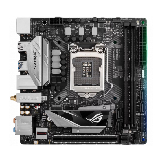
Page 14: Motherboard Layout
1.1.2 Motherboard layout 17.0cm(6.7in) BOOT_DEVICE_LED VGA_LED DRAM_LED CPU_LED CPU_FAN AIO_PUMP EATX12V RGBLED HDMI DIGI +VRM LAN2_USB3_78 Realtek ® (Bottom) RTL8111H USB3_56 LGA1151 LAN1_USB3_34 Intel ® (Bottom) I219V M.2(WIFI) 128Mb BIOS BATT_CON Super Intel ® H270 2260 AAFP 2280 AUDIO CLRTC CHA_FAN SupremeFX S1220A Codec... - Page 15 17.0cm(6.7in) ASUS STRIX H270I GAMING...
-
Page 16: Central Processing Unit (Cpu)
12. USB 3.0 connectors (20-1 pin USB3_12) 1-11 13. Clear RTC RAM jumper (2-pin CLRTC) 14. TPM connector (14-1 pin TPM) 1-13 15. Front panel audio connector (10-1 pin AAFP) 1-12 16. RTC Battery header (2-pin BATT_CON) 1.1.3 Central Processing Unit (CPU) The motherboard comes with a surface mount LGA1151 socket designed for the 7th / 6th Generation Intel Core™ i7 / Intel Core™ i5 / Intel Core™ i3, Pentium , and Celeron ® ® ® ® ® processors. STRIX H270I GAMING CPU socket LGA1151 Chapter 1: Product Introduction... -
Page 17: System Memory
• Ensure that all power cables are unplugged before installing the CPU. • Upon purchase of the motherboard, ensure that the PnP cap is on the socket and the socket contacts are not bent. Contact your retailer immediately if the PnP cap is missing, or if you see any damage to the PnP cap/socket contacts/motherboard components. ASUS will shoulder the cost of repair only if the damage is shipment/ transit-related. • Keep the cap after installing the motherboard. ASUS will process Return Merchandise Authorization (RMA) requests only if the motherboard comes with the cap on the LGA1151 socket. • The product warranty does not cover damage to the socket contacts resulting from incorrect CPU installation/removal, or misplacement/loss/incorrect removal of the PnP cap. 1.1.4 System memory The motherboard comes with two DDR4 (Double Data Rate 4) Quad Inline Memory Modules (DIMM) slots. A DDR4 module is notched differently from a DDR, DDR2, or DDR3 module. DO NOT install a DDR, DDR2, or DDR3 memory module to the DDR4 slot. STRIX H270I GAMING 288-pin DDR4 DIMM sockets Recommended memory configurations ASUS STRIX H270I GAMING... - Page 18 For more details, refer to the Microsoft support site at http://support.microsoft. ® com/kb/929605/en-us. • The design of the DIMM fan may vary. Ensure that the DIMM fan fits to the motherboard. • The default memory operation frequency is dependent on its Serial Presence Detect (SPD), which is the standard way of accessing information from a memory module. Under the default state, some memory modules for overclocking may operate at a lower frequency than the vendor-marked value. • For system stability, use a more efficient memory cooling system to support a full memory load (2 DIMMs) or overclocking condition. • Memory modules with memory frequency higher than 2133MHz and their corresponding timing or the loaded XMP profile is not the JEDEC memory standard. The stability and compatibility of the memory modules depend on the CPU’s capabilities and other installed devices. • Always install the DIMMS with the same CAS Latency. For an optimum compatibility, we recommend that you install memory modules of the same version or data code (D/C) from the same vendor. Check with the vendor to get the correct memory modules. • ASUS exclusively provides hyper DIMM support function. • Hyper DIMM support is subject to the physical characteristics of individual CPUs. Load the X.M.P. or D.O.C.P. settings in the BIOS for the hyper DIMM support. • Visit the ASUS website for the latest QVL. Chapter 1: Product Introduction...
-
Page 19: Expansion Slots
1.1.5 Expansion slots Unplug the power cord before adding or removing expansion cards. Failure to do so may cause you physical injury and damage motherboard components. STRIX H270I GAMING Slot No. Slot Description PCIe x16 slot ASUS STRIX H270I GAMING... -
Page 20: Headers
1.1.6 Headers Clear RTC RAM (2-pin CLRTC) This header allows you to clear the CMOS RTC RAM data of the system setup information such as date, time, and system passwords. CLRTC PIN 1 STRIX H270I GAMING Clear RTC RAM To erase the RTC RAM: Turn OFF the computer and unplug the power cord. Use a metal object such as a screwdriver to short the two pins. Plug the power cord and turn ON the computer. Hold down the <Del> key during the boot process and enter BIOS setup to re-enter data. If the steps above do not help, remove the onboard battery and short the two pins again to clear the CMOS RTC RAM data. After clearing the CMOS, reinstall the battery. RTC Battery header (2-pin BATT_CON) This header is for the lithium CMOS battery. BATT_CON PIN 1 STRIX H270I GAMING BATT_CON Chapter 1: Product Introduction... - Page 21 RGB header (4-pin RGB_HEADER) This header is for RGB LED strips. RGB_HEADER +12V PIN 1 STRIX H270I GAMING RGB_HEADER connector The RGB header supports 5050 RGB multi-color LED strips (12V/G/R/B), with a maximum power rating of 2A (12V), and no longer than 2 m. Before you install or remove any component, ensure that the ATX power supply is switched off or the power cord is detached from the power supply. Failure to do so may cause severe damage to the motherboard, peripherals, or components. • Actual lighting and color will vary with LED strip. • If your LED strip does not light up, check if the RGB LED extension cable and the RGB LED strip is connected in the correct orientation, and the 12V connector is aligned with the 12V header on the motherboard. • The LED strip will only light up when the system is operating. • The LED strips are purchased separately. ASUS STRIX H270I GAMING...
-
Page 22: Onboard Leds
CPU_LED [red] STRIX H270I GAMING CPU/DRAM/ BOOT_DEVICE/VGA LED RGB LED The RGB LED lighting control provides several lighting schemes, which allow you to customize your favorite LED effect. You can set your favorite LED effect to cast a stunning multi-color glow across your build, change shades to indicate CPU temperature, pulsate in time to the beat of your music, or set your favorite color for each pair of LEDs. RGB1 RGB2 RGB3 RGB4 RGB5 RGB6 RGB LED(Bottom) RGB7 RGB8 RGB9 RGB10 RGB11 RGB12 STRIX H270I GAMING RGB LED Lighting Chapter 1: Product Introduction 1-10... -
Page 23: Internal Connectors
IntA_P1_SSTX+ IntA_P2_SSTX+ IntA_P1_D- IntA_P2_D- IntA_P1_D+ IntA_P2_D+ STRIX H270I GAMING USB3.0 Front panel connector The USB 3.0 module is purchased separately. Speaker connector (4-pin SPEAKER) The 4-pin connector is for the chassis-mounted system warning speaker. The speaker allows you hear system beeps and warnings. SPEAKER Speaker Out... - Page 24 SENSE2_RETUR SENSE_SEND PORT2 R SENSE1_RETUR PORT1 R PORT1 L AGND PIN 1 HD-audio-compliant pin definition STRIX H270I GAMING Analog front panel connector We recommend that you connect a high-definition front panel audio module to this connector to avail of the motherboard’s high-definition audio capability. ATX power connectors (24-pin EATXPWR, 8-pin EATX12V) These connectors are for ATX power supply plugs. The power supply plugs are designed to fit these connectors in only one orientation. Find the proper orientation and push down firmly until the connectors completely fit. EATX12V EATXPWR +3 Volts +12 Volts...
- Page 25 TPM connector (14-1 pin TPM) This connector supports a Trusted Platform Module (TPM) system, which securely stores keys, digital certificates, passwords and data. A TPM system also helps enhance network security, protect digital identities, and ensures platform integrity. PIN 1 STRIX H270I GAMING TPM connector The TPM module is purchased separately. Intel Serial ATA 6 Gb/s connectors (7-pin SATA 6G_1~4) ® These connectors connect to Serial ATA 6 Gb/s hard disk drives via Serial ATA 6 Gb/s signal cables. If you installed Serial ATA hard disk drives, you can create a RAID 0, 1, 5, and 10 configuration with the Intel Rapid Storage Technology through the onboard Intel ® ® H270 chipset. SATA6G_1 SATA6G_3 RSATA_TXP1 RSATA_TXP3 RSATA_TXN1...
- Page 26 These are not jumpers! Do not place jumper caps on the fan connectors! • Ensure that the CPU fan cable is securely installed to the CPU fan connector. CPU_FAN AIO_PUMP CHA_FAN STRIX H270I GAMING Fan connectors • The CPU_FAN connector supports the CPU fan of maximum 1A (12 W) fan power. • Connect the fan of your water cooling kit to the CPU_FAN connector. Chapter 1: Product Introduction 1-14...
- Page 27 M.2 sockets (M.2_1~2) These sockets allow you to install M.2 SSD modules. M.2_1(SOCKET3) M.2_2(SOCKET3) 2280 2260 (Bottom) STRIX H270I GAMING M.2(SOCKET3) • M.2_1 socket supports SATA/ PCIe 3.0 x4 mode M Key design and type 2242/ 2260/ 2280 SATA/ PCIe 3.0 x4 storage devices. • M.2_2 socket supports PCIe 3.0 x4 M Key design and type 2242/ 2260/ 2280 PCIe storage devices. • Both M.2_1 and M.2_2 sockets support IRST (Intel Rapid Storage Technology). ® • The M.2 SSD module is purchased separately. • For a 2242 storage device, use the bundled 2242 mounting kit. • Before installing a 2242 M.2 SSD module, ensure that the mounting kit is properly installed with the bigger screw hole on the 2260 standoff. To install a 2242 M.2 SSD module: Align the bigger hole on the mounting kit with the 2260 standoff and secure it with a screw.
- Page 28 System panel connector (10-1 pin PANEL) This connector supports several chassis-mounted functions. F_PANEL (NC) HWRST# Ground PWR_LED- HDD_LED- PWR_LED+ HDD_LED+ PIN 1 STRIX H270I GAMING System panel connector • System power LED (2-pin PWR_LED) This 2-pin connector is for the system power LED. Connect the chassis power LED cable to this connector. The system power LED lights up when you turn on the system power, and blinks when the system is in sleep mode. • Hard disk drive activity LED (2-pin HDD_LED) This 2-pin connector is for the HDD Activity LED. Connect the HDD Activity LED cable to this connector. The HDD LED lights up or flashes when data is read from or written to the HDD. • ATX power button/soft-off button (2-pin PWR_BTN) This connector is for the system power button.
-
Page 29: Chapter 2: Basic Installation
2.1.1 Motherboard installation Install the ASUS I/O Shield to the chassis rear I/O panel. Place the motherboard into the chassis, ensuring that its rear I/O ports are aligned to the chassis’ rear I/O panel. - Page 30 Place six (6) screws into the holes indicated by circles to secure the motherboard to the chassis. DO NOT overtighten the screws! Doing so can damage the motherboard. Chapter 2: Basic Installation...
-
Page 31: Cpu Installation
Ensure that you install the correct CPU designed for LGA1151 socket only. DO NOT install a CPU designed for LGA1155 and LGA1156 sockets on the LGA1151 socket. ASUS will not cover damages resulting from incorrect CPU installation/removal, incorrect CPU orientation/placement, or other damages resulting from negligence by the user. -
Page 32: Cpu Heatsink And Fan Assembly Installation
2.1.3 CPU heatsink and fan assembly installation Apply the Thermal Interface Material to the CPU heatsink and CPU before you install the heatsink and fan, if necessary. To install the CPU heatsink and fan assembly Chapter 2: Basic Installation... - Page 33 To uninstall the CPU heatsink and fan assembly ASUS STRIX H270I GAMING...
-
Page 34: Dimm Installation
2.1.4 DIMM installation To remove a DIMM Chapter 2: Basic Installation... -
Page 35: Atx Power Connection
2.1.5 ATX power connection Ensure to connect the 8-pin power plug. ASUS STRIX H270I GAMING... -
Page 36: Sata Device Connection
2.1.6 SATA device connection Chapter 2: Basic Installation... -
Page 37: Front I/O Connector
2.1.7 Front I/O connector To install front panel connector To install USB 3.0 connector USB 3.0 To install front panel audio connector AAFP 2.1.8 Expansion card installation To install PCIe x16 cards ASUS STRIX H270I GAMING... -
Page 38: Installation
2.1.9 M.2 installation Chapter 2: Basic Installation 2-10... -
Page 39: Wi-Fi Antenna Installation
2.1.10 Wi-Fi antenna installation Installing the ASUS 2x2 dual band W-Fi antenna Connect the bundled ASUS 2x2 dual band Wi-Fi antenna connector to the Wi-Fi ports at the back of the chassis. IO Shield • Ensure that the ASUS 2x2 dual band Wi-Fi antenna is securely installed to the Wi-Fi ports. • Ensure that the antenna is at least 20 cm away from all persons. The illustration above is for reference only. The I/O port layout may vary with models, but the Wi-Fi antenna installation procedure is the same for all models. -
Page 40: Motherboard Rear And Audio Connections
Motherboard rear and audio connections 2.2.1 Rear I/O connection Rear panel connectors DisplayPort Wi-Fi 802.11 a/b/g/n/ac, Bluetooth V4.0 Intel and Realtek LAN ports* USB 3.0 ports ® ® Audio I/O ports** HDMI port Optical S/PDIF Out port * and ** : Refer to the tables for LAN port LEDs and audio port definitions. * LAN ports LED indications Activity Link LED Speed LED... -
Page 41: Audio I/O Connections
Mic In Mic In Orange – – Center/Subwoofer Center/Subwoofer Black – Rear Speaker Out Rear Speaker Out Rear Speaker Out 2.2.2 Audio I/O connections Audio I/O ports Connect to Headphone and Mic Connect to Stereo Speakers ASUS STRIX H270I GAMING 2-13... - Page 42 Connect to 2 channel Speakers Connect to 4 channel Speakers Connect to 5.1 channel Speakers If you are using Windows 8.1/10 platform, use only the light blue audio port for Side ® Speaker Out in a 5.1-channel configuration. Chapter 2: Basic Installation 2-14...
- Page 43 Connect to 7.1 channel Speakers ASUS STRIX H270I GAMING 2-15...
-
Page 44: Starting Up For The First Time
Starting up for the first time After making all the connections, replace the system case cover. Ensure that all switches are off. Connect the power cord to the power connector at the back of the system chassis. Connect the power cord to a power outlet that is equipped with a surge protector. Turn on the devices in the following order: Monitor External SCSI devices (starting with the last device on the chain) - Page 45 ASUS STRIX H270I GAMING 2-17...
-
Page 46: Chapter 3: Bios Setup
BIOS Setup Knowing BIOS The new ASUS UEFI BIOS is a Unified Extensible Interface that complies with UEFI architecture, offering a user-friendly interface that goes beyond the traditional keyboard- only BIOS controls to enable a more flexible and convenient mouse input. You can easily navigate the new UEFI BIOS with the same smoothness as your operating system. -
Page 47: Bios Setup Program
RTC RAM via the Clear CMOS jumper. • The BIOS setup program does not support the Bluetooth devices. Please visit ASUS website for the detailed BIOS content manual. BIOS menu screen The BIOS Setup program can be used under two modes: EZ Mode and Advanced Mode. -
Page 48: Ez Mode
Search on the FAQ Loads optimized Click to display boot devices default settings Selects the boot device priority The boot device options vary depending on the devices you installed to the system. ASUS STRIX H270I GAMING... -
Page 49: Advanced Mode
3.2.2 Advanced Mode The Advanced Mode provides advanced options for experienced end-users to configure the BIOS settings. The figure below shows an example of the Advanced Mode. Refer to the following sections for the detailed configurations. To switch from EZ Mode to Advanced Mode, click Advanced Mode(F7) or press the <F7> hotkey. - Page 50 Q-Fan Control(F6) This button above the menu bar displays the current settings of your fans. Use this button to manually tweak the fans to your desired settings. Refer to section 3.2.3 QFan Control for more information. ASUS STRIX H270I GAMING...
- Page 51 Move your mouse over this button to show a QR code, scan this QR code on your mobile device to connect to the BIOS FAQ web page of the ASUS support website. You can also scan the following QR code: Hot keys This button above the menu bar contains the navigation keys for the BIOS setup program.
-
Page 52: Qfan Control
Click to activate DC Mode configured PWM Mode Select a profile to Click to apply the fan setting apply to your fans Click to undo the Click to go back to main menu changes Select to manually configure your fans ASUS STRIX H270I GAMING... - Page 53 Configuring fans manually Select Manual from the list of profiles to manually configure your fans’ operating speed. Speed points Select to manually configure your fans To configure your fans: Select the fan that you want to configure and to view its current status. Click and drag the speed points to adjust the fans’...
-
Page 54: My Favorites
My Favorites is your personal space where you can easily save and access your favorite BIOS items. My Favorites comes with several performance, power saving, and fast boot related items by default. You can personalize this screen by adding or removing items. ASUS STRIX H270I GAMING... - Page 55 Adding items to My Favorites To add BIOS items: Press <F3> on your keyboard or click from the BIOS screen to open Setup Tree Map screen. On the Setup Tree Map screen, select the BIOS items that you want to save in My Favorites screen.
-
Page 56: Main Menu
Selecting a very high memory frequency may cause the system to become unstable! If this happens, revert to the default setting. Internal CPU Power Management The subitems in this menu allow you to set the CPU ratio and their features. ASUS STRIX H270I GAMING 3-11... -
Page 57: Advanced Menu
Intel(R) SpeedStep(tm) [Auto] This item allows the operating system to dynamically adjust the processor voltage and cores frequency, resulting to a decreased average power consumption and decreased average heat production. Configuration options: [Auto] [Disabled] [Enabled] Turbo Mode Parameters Long Duration Package Power Limit [Auto] Allows you to limit the Turbo Ratio’s time duration that exceeds the TDP (Thermal Design Power) for maximum performance. -
Page 58: System Agent (Sa) Configuration
SMART Self Test [On] SMART (Self-Monitoring, Analysis and Reporting Technology) is a monitoring system that shows a warning message during POST (Power-on Self Test) when an error occurs in the hard disks. Configuration options: [On] [Off] ASUS STRIX H270I GAMING 3-13... -
Page 59: Pch-Fw Configuration
Hot Plug [Disabled] (SATA6G_1 (Charcoal Black) ~ SATA6G_4(Charcoal Black)) These items allow you to enable/disable SATA Hot Plug Support. Configuration options: [Disabled] [Enabled] 3.6.6 PCH-FW Configuration This item allows you to configure the firmware TPM. 3.6.7 Onboard Devices Configuration HD Audio Controller [Enabled] This item allows you to use the Azalia High Definition Audio Controller. -
Page 60: Monitor Menu
For better compatibility, enable the CSM to fully support the non-UEFI driver add-on devices or the Windows UEFI mode. ® [Disabled] Disable the CSM to fully support the Windows Security Update and ® Security Boot. ASUS STRIX H270I GAMING 3-15... -
Page 61: Tool Menu
3.9.1 ASUS EZ Flash 3 Utility This item allows you to run ASUS EZ Flash 3. When you press <Enter>, a confirmation message appears. Use the left/right arrow key to select between [Yes] or [No], then press <Enter> to confirm your choice. -
Page 62: Secure Erase
To launch Secure Erase, click Tool > Secure Erase on the Advanced mode menu. Check the ASUS support site for a full list of SSDs tested with Secure Erase. The drive may become unstable if you run Secure Erase on an incompatible SSD. -
Page 63: Exit Menu
® ASUS EZ Flash 3: Updates the BIOS using a USB flash drive. ASUS CrashFree BIOS 3: Restores the BIOS using the motherboard support DVD or a USB flash drive when the BIOS file fails or gets corrupted. 3.11.1... -
Page 64: Asus Ez Flash 3
3.11.2 ASUS EZ Flash 3 ASUS EZ Flash 3 allows you to download and update to the latest BIOS through the Internet without having to use a bootable floppy disk or an OS-based utility. Updating through the Internet varies per region and Internet conditions. Check your local Internet connection before updating through the Internet. - Page 65 To update the BIOS by Internet: Enter the Advanced Mode of the BIOS setup program. Go to the Tool menu to select ASUS EZ Flash Utility and press <Enter>. Select via Internet. Press the Left/Right arrow keys to select an Internet connection method, and then press <Enter>.
-
Page 66: Asus Crashfree Bios 3
The BIOS file in the motherboard support DVD may be older than the BIOS file published on the ASUS official website. If you want to use the newer BIOS file, download the file at https://www.asus.com/support/ and save it to a USB flash drive. - Page 67 Chapter 3: BIOS Setup 3-22...
-
Page 68: Appendix
Consult the dealer or an experienced radio/TV technician for help. The use of shielded cables for connection of the monitor to the graphics card is required to assure compliance with FCC regulations. Changes or modifications to this unit not expressly approved by the party responsible for compliance could void the user’s authority to operate this equipment. ASUS STRIX H270I GAMING... - Page 69 Compliance Statement of Innovation, Science and Economic Development Canada (ISED) Compliance Statement of Innovation, Science and Economic Development Canada (ISED) This Class B digital apparatus complies with Canadian ICES-003, RSS-210, and CAN ICES- 3(B)/NMB-3(B). This device complies with Industry Canada license exempt RSS standard(s). Operation is subject to the following two conditions: (1) this device may not cause interference, and (2) this device must accept any interference, including interference that may cause undesired operation of the device.
- Page 70 ASUS Recycling/Takeback Services ASUS recycling and takeback programs come from our commitment to the highest standards for protecting our environment. We believe in providing solutions for you to be able to responsibly recycle our products, batteries, other components as well as the packaging materials.
- Page 71 FCC Bluetooth Wireless Compliance The antenna used with this transmitter must not be co-located or operated in conjunction with any other antenna or transmitter subject to the conditions of the FCC Grant. Bluetooth Industry Canada Statement This Class B device meets all requirements of the Canadian interference-causing equipment regulations.
- Page 72 2014/53/EU. Cijeli di: https://www.asus.com/support/ tekst EU izjave o sukladnosti dostupan je na https://www.asus.com/support/ WiFi yang Beroperasi pada 5150-5350 MHz akan terbatas untuk penggunaan WiFi koji radi na opsegu frekvencija 5150-5350 MHz bit će ograničen na...
- Page 73 ASUSTek Computer Inc. tukaj izjavlja, da je ta naprava skladna s temeljnimi zahtevami in drugimi relevantnimii določili Direktive 2014/53/EU. Polno besedilo izjave EU o skladnosti je na voljo na https://www.asus.com/support/ WiFi, ki deluje v pasovnem območju 5150–5350 MHz, mora biti v državah, navedenih v spodnjem seznamu, omejen na notranjo uporabo: Declaración de conformidad simplificada para la UE...
-
Page 74: Asus Contact Information
+1-510-739-3777 +1-510-608-4555 Web site http://www.asus.com/us/ Technical Support Support fax +1-812-284-0883 Telephone +1-812-282-2787 Online support http://qr.asus.com/techserv ASUS COMPUTER GmbH (Germany and Austria) Address Harkort Str. 21-23, 40880 Ratingen, Germany +49-2102-959931 Web site http://www.asus.com/de Online contact http://eu-rma.asus.com/sales Technical Support Telephone +49-2102-5789555 Support Fax... - Page 75 800 Corporate Way, Fremont Phone/Fax No: (510)739-3777/(510)608-4555 hereby declares that the product Product Name : Motherboard Model Number : STRIX H270I GAMING Conforms to the following specifications: FCC Part 15, Subpart B, Unintentional Radiators Supplementary Information: This device complies with part 15 of the FCC Rules. Operation is subject to the...
Need help?
Do you have a question about the STRIX H270I GAMING and is the answer not in the manual?
Questions and answers