
Subscribe to Our Youtube Channel
Related Manuals for Heyl Testomat ECO


Summary of Contents for Heyl Testomat ECO
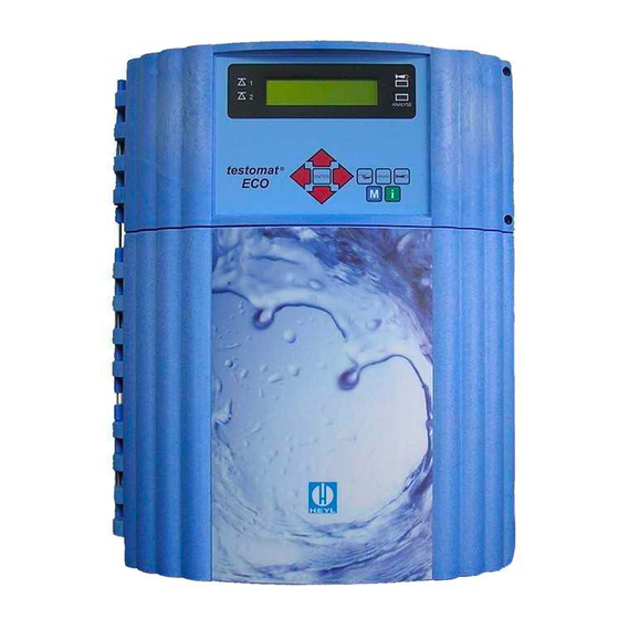
- Page 1 Operating Instructions ® Testomat ECO Online analysis instrument for residual total hardness (water hardness)
-
Page 2: Table Of Contents
Cleaning ....................6 De-installation ..................6 Disposal ....................7 Scope of delivery ................7 Performance specifications ............... 7 ® Indicators for Testomat ECO instruments ........... 8 Application instructions ................. 9 Installation ..................10 ® Operating Testomat ECO in the pressure range 0.3 to 1 bar ... 10 ®... - Page 3 Description of maintenance work ............40 Service instructions ................41 ® Testomat ECO spare parts and accessories ........ 42 Accessories ..................44 ® Check List Testomat ECO ..............45 Technical data ................... 47 Conformity Declaration ............... 48 ® Product overview Testomat 2000 -Instruments ......48...
-
Page 4: Important Safety Information
These operating instructions must always be passed on to the new ® owner should Testomat ECO change hands. Always adhere to hazard warnings and safety tips when using reagents, chemicals and cleaning agents. Please adhere to the re- spective safety data sheet! Download the safety data sheets for the supplied reagents at http://www.heyl.de. -
Page 5: Warning Notices In Dthese Instructions
Do not carry out any changes or actions at the instrument which are not described in these instructions; failure to adhere to these instructions will negatively affect any warranty claims that you make thereafter. Trouble-free operation of Testomat ECO ® is only guaranteed when ®... -
Page 6: Installation
NOTE ® supply. If necessary, use a mains filter to protect Testomat ECO against interference voltages caused, e.g., by solenoid valves or large motors. Never lay connecting cables parallel to power cables. Operation ... -
Page 7: Disposal
In water with a pH level < 4, deposits or corrosion can occur on the magnetic valve in the valve block located on the measured chamber. ® In this case, you can order the Testomat ECO with a different valve block (Art. No. 40018). This magnetic valve is not affected by media,... -
Page 8: Indicators For Testomat Eco Instruments
Performance specifications ® Indicators for Testomat ECO instruments Parameter/Indicator type Water hardness TH 2005 TH 2025 TH 2100 TH 2250 0.25 – 2.50 1.0 – 10.0 2.5 – 25.0 °dH 0.05 - 0.50 (resolution) (0.01) (0.05) (0.2) (0.5) 0.09 – 0.89 0.45 –... -
Page 9: Application Instructions
- Are the doors of the instrument closed properly? - Is the instrument heavily soiled? Maintenance and servicing instructions (For more information, please refer to the section entitled ® “Maintenance” and the "Maintenance manual of Testomat 2000 ® Testomat ECO... -
Page 10: Installation
Risks resulting from incorrect installation! WARNING ® Install Testomat ECO at a location where it is protected against dripping or splash water, dust and aggressive substances – e. g. in a switch cabinet or on a suitable wall. Information for trouble-free operation ®... -
Page 11: Connecting The Water Inlet And Outlet
The measuring water is taken from the main water line of the water ® treatment plant and fed to the inlet connection of Testomat ECO The instrument is equipped with a plug connector for plastic hoses 6/4 x 1 (external diameter 6 mm/ internal diameter 4 mm, wall thick- ... -
Page 12: Connecting The Power Supply And Devices
Connect the instrument to the protective earth conductor (for 230/115 VAC). ® against interference voltages – e.g. via a Protect Testomat ECO mains filter. Shield the instrument against strong electromagnetic fields. ® Block diagram Testomat ECO Drawn relay positions: Instrument de-energised, mains: 230/115 V... -
Page 13: Internal Design Testomat Eco
Installation ® Internal design Testomat ECO Terminal strip for inputs Stop, IN2, output OUT, +12 V for turbine Mains switch Terminal strip for power input and power output ... -
Page 14: Connecting The Mains Voltage
Installation Connecting the mains voltage Only connect the instrument to the specified mains voltage. Refer to the rating plate for the appropriate mains voltage. Connect the cables as follows: Loosen both fastening screws and open the upper door. The terminal box is now accessible. -
Page 15: Connecting The Plant Components
Installation Connecting the plant components Connect the plant components to the output terminals of relays 9 Connection example: to 17 (e.g. valves). Limit value contact LV 1 switches mains voltage If the plant components require mains voltage, connect the ... -
Page 16: Connecting The Inputs And Outputs
Installation Connecting the inputs and outputs ® Testomat ECO has the following connections for control and moni- toring functions. Do not connect external voltage to these connections! Ensure that the leads are held securely in the terminals ... -
Page 17: Commissioning
Commissioning Commissioning ® Trouble-free operation of Testomat ECO is only guaranteed CAUTION ® when using Heyl Testomat indicators! Inserting the indicator bottle Open the lower housing door by pulling on the right-hand side. Remove the cap from the indicator bottle. -
Page 18: Instrument Settings And Data Input
® Switching Testomat ECO on/off (1) Mains switch Use this switch to switch the instrument on or off. (2) Instrument fuse (inside the instrument) ® This fuse protects Testomat ECO and the outputs against overloads and short circuits. -
Page 19: Display Functions
Functions of the operating and display elements Display functions ╘╛ 1 Limit value status displays (red/green) The display 1 illuminates red if limit value 1 has been reached or exceeded. The display 1 illuminates green if the value falls below the limit value. -
Page 20: Operating Elements And Function Keys
Functions of the operating and display elements Operating elements and function keys Program- ming keys (cursor block) ® Function keys Manually start an analysis via the "Manual" Set the instrument to standby mode via the "STANDBY" ... -
Page 21: Operating System
Functions of the operating and display elements Testomat instrument Operating system (display) in display mode SELECTING FUNCTIONS (example: "select operating mode") Press the "M" key "SERVICE" or "Basic program" is displayed Use the cursor block to select the desired menu item "Basic program"... -
Page 22: Entering Basic Program Data
Under the menu item "OPERATING MODE" it is possible to select the type of analysis controller. Time control or quantity control via water ® meter, or a combination of both, is possible with Testomat ECO Shortest interval = 0 minutes between analyses. Largest interval = 99 Time control minutes. -
Page 23: Setting The Analysis Interval (Interval Pause)
Entering basic program data Setting the analysis interval (interval pause) If the analysis is triggered via a timer, the interval between two anal- yses is determined by the interval pause (plus flushing time). The shortest interval pause can be 0 minutes. In this case, analyses are carried out continuously. -
Page 24: Selecting The Quantity Control/Time Priority
60 seconds. Flushing starts by simultaneously opening the inlet and the outlet ® valve of Testomat ECO Duration of the analysis interval NOTE ... -
Page 25: Limit Value Monitoring
Entering basic program data Limit value monitoring It is possible to program the limit values on a continuous scale. The limit value range depends on the used indicator type and the pro- grammed unit. It is possible to monitor two limit values. One limit value output is available for each limit value. -
Page 26: Switch Functions Of The Limit Value Outputs Lv1 And Lv2
Entering basic program data Switch functions of the limit value outputs LV1 and LV2 Switch function 0, duration If the limit value LV1 or LV2 has been exceeded, the output relay LV1 Switch functions or LV2 switches. If the measured value falls below the limit value diagram LV1 or LV2, the relevant relay drops out again. -
Page 27: Bob Operation (Operation Without Permanent Supervision)
Entering basic program data BOB operation (operation without permanent supervision) Operation without permanent supervision is a safety relevant feature when using the instrument as a water hardness monitoring unit for monitoring steam boiler plants in accordance with TRD 604. If the BOB function has been programmed, the instrument continu- ously checks the available amount of indicator. -
Page 28: Description Of The Signal Inputs/Outputs
Description of the signal inputs/outputs Description of the signal in- puts/outputs Connecting the signal inputs CAUTION Only connect the signal inputs "Stop" and "IN" with volt-free con- tacts! The connection of external voltages would damage the instrument! Stop input Function Contact type Test... -
Page 29: Water Meter Input
Description of the signal inputs/outputs Water meter input Function Contact type Test Action time Terminals 20,21 normally Quantity recording None open/normally closed for starting an anal- Water meter or turbine ysis input (isolated!) Connecting a turbine Besides the connections 20 and 21, an additional power supply is required for connecting a turbine. - Page 30 Description of the signal inputs/outputs...
-
Page 31: Calculating The Output Currents
Description of the signal inputs/outputs Monitoring the measuring point A printer can be connected to record the analysis results. The instru- ment is equipped with a programmable current output for this pur- pose (optional 0-20 mA or 4-20 mA). The example on the left displays the current profile in the 0-20 mA range. -
Page 32: Description Of The Relay Outputs
Description of the relay outputs Description of the relay outputs All relay outputs are neutral contacts. This ensures that all connection options are available. The switching of mains voltage and external voltage, and the direct switching of inputs, e.g. a process controller, can be realised. -
Page 33: Alarm/Message (Fault Message Output)
Description of the relay outputs Alarm/Message (fault message output) The instrument is equipped with an ALARM relay output for signalling faults. The fault message is displayed via the fault LED and on the display. Error messages NOTE The error message can only be deleted once the error has been eliminated! The "Alarm"... -
Page 34: Information Menu "I
Information menu "i" Information menu "i" Request current settings and statuses of the instrument in the Infor- mation menu. Call (1) Use the key to open the information menu "i". Call (1) Request options: Operating values, program values Opening the information menu for checking or requesting settings and operating values. -
Page 35: Program Menu "M
Program menu "M" Program menu "M" Call (1) Service (2) Use the key to open the program menu "M". Input indicator (3) Enter the new filling levels after each refill or indicator bottle Programming of: Indicator, manual operation, flush, flush chamber, change. - Page 36 Program menu "M" Language (9) GERMAN Select the desired language for the display. English Francais Diagnosis (10) Italiano It is possible to request a list of current statuses of the signal inputs Polski and outputs. Active statuses are marked with an *. (See "Structure of Nederlands the basic program").
-
Page 37: Structure Of The Basic Program
Program menu "M" Structure of the basic program Call the basic factory program by simultaneously pressing and holding down the "M" and "i" keys while switching on the instrument. CAUTION, the most recent programming will be lost! -
Page 38: Error Messages/Troubleshooting
- Indicator shelf life exceeded Replace stirring bar - Third-party indicator in the Replace indicator, only CANCEL WITH HORN KEY use HEYL Testomat instrument 2000® indicator Abbreviations: Ff.: = Function fault, Mf.: = Measuring fault... -
Page 39: Further Information
Maintenance Further information Error Possible causes Remedies Load too high - Incorrect measured value at the output or Current interface functions incorrectly no power supplied Unit is not functioning, even though it - Fuse F9, F5 or F2 (240 Replace fuses ... -
Page 40: Description Of Maintenance Work
The maintenance manual contains a detailed description of mainte- nance work. The measures described here provide a brief overview. ® ® Please refer to the Testomat 2000 /Testomat ECO maintenance manual for all further maintenance details Cleaning measures CAUTION... -
Page 41: Service Instructions
Close the manually-operated valve of the branch line to Testomat ® ® via the “Flush” function Depressurise the lines of Testomat ECO in MANUAL MODE. Switch of the instrument and loosen the hose connections at the filter housing. -
Page 42: Testomat Eco Spare Parts And Accessories
Testomat ECO® spare parts and accessories ® Testomat ECO spare parts and ac- cessories Art. No. Pressure controller Art. No. Instrument spare parts list 40125 Controller / filter receiver, complete 31582 Fuse GS-M 5x20E 4A 40120 Controller / filter receiver... - Page 43 Testomat ECO® spare parts and accessories...
-
Page 44: Accessories
Testomat ECO® spare parts and accessories Accessories Indicator type Range Art. no.: Water hardness 0.05 – 0.5 °dH TH2005 152005 Water hardness 0.25 – 2.5 °dH TH2025 152025 Water hardness 1.0 – 10.0 °dH TH2100 152100 Water hardness 2.5 – 25.0 °dH... -
Page 45: Check List Testomat Eco
® Check List Testomat ECO Dear customers and service technicians, This check list cannot replace your expertise or extensive experience in fault resolution. It is intended to support fast and systematic error diagnosis and error documentation. This list does not claim to be complete. We are therefore always grateful for any advice and information you may be able to provide. -
Page 46: Instrument Settings
Instrument settings Caution! Your settings may be deleted if repairs are carried out. Therefore, note down your instrument settings in the table below before sending the instrument to our service team for repairs. Please enclose a copy of the table with the instrument. If you have noted down the settings, they can be easily re-entered by your service staff once any repairs have been completed. -
Page 47: Technical Data
Our manuals are updated regularly. If you have an older version (see version at the back of the manual) you will find the current manual on our website www.heyl.de on the download page. -
Page 48: Conformity Declaration
Technical data Conformity Declaration... -
Page 49: Product Overview Testomat 2000 -Instruments
Product overview Testomat 2000®-Instruments ® Product overview Testomat 2000 -Instruments Model/Type Measuring Parameter Measuring Applications/Functions Range Testomat 2000 ® • Water hardness • Universal for water treatment 0.05-25 °dH plants • Carbonate hardness 0,5-20 °dH • allowed for boiler houses •... - Page 50 Gebrüder Heyl Analysentechnik GmbH & Co. KG Orleansstraße 75b D 31135 Hildesheim Testomat_ECO_GB_170508.docx www.heyl.de Scan the code and visit us on our website!
Need help?
Do you have a question about the Testomat ECO and is the answer not in the manual?
Questions and answers