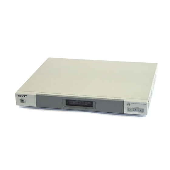
Sony DSC-1024HD Service Manual
Digital scan converter
Hide thumbs
Also See for DSC-1024HD:
- Operating instructions manual (23 pages) ,
- Instructions manual (25 pages) ,
- Operating instructions manual (23 pages)
Table of Contents
Advertisement
SERVICE MANUAL
Signal input
VIDEO 1 IN
VIDEO 2 IN
VIDEO 3 IN
AUDIO IN 1, 2, 3 (L/R) RCA pin jack, more than 10 kilohms
MICROFILM
SPECIFICATIONS
Composite video/reference input
BNC connector × 2 (loop-through),
75 ohms (automatic termination)
NTSC
/PAL
, 1 Vp-p typical
3.58
4.43
Black burst signal for the gen-lock
function*
S video (Y/C)
4-pin mini DIN connector × 2 (loop-
through), 75 ohms (automatic
termination)
Y: 1 Vp-p typical, sync negative
C: 0.286 Vp-p (NTSC)/0.3 Vp-p
(PAL) typical
RGB/component/composite video
D-sub 15-pin, 3-row x 2 (loop-
through), 75 ohms/high
impedance
R/G/B: 0.714 Vp-p
H/V or composite sync: 1 to 5 Vp-p
Y/B-Y/R-Y: 0.7 Vp-p (NTSC/PAL,
sync on Y)
Composite video: 1 Vp-p
(NTSC
/PAL
)
3.58
4.43
RGB/component
D-sub 15-pin, 3-row connector × 2
(loop-through), 75 ohms/high
impedance
R/G/B: 0.714 Vp-p (sync on G
acceptable)
H/V or composite sync: 1 to 5 Vp-p
Y/B-Y/R-Y: 0.7 Vp-p typical
(NTSC/PAL, sync on Y)
0 dBs (1 Vrms) max.
DSC-1024HD
Canadian Model
Video processing
Capture range
Horizontal rate: 15.6 to 70 kHz,
Vertical rate: 50 to 120 Hz
Preset signal
Input: 10 formats
Output: 7 formats
Gen-lock output: NTSC or PAL
(See page 49.)
1,152 × 1,152 × 24 bits (RGB total)
Video memory
Sampling rate
14.3 to 40 MHz offset phase max.
(equivalent to 80 MHz sampling)
Output pixel clock
14.3 to 50 MHz max.
General
Power requirements
100 to 120 V AC, 50/60 Hz, 0.4 A
200 to 240 V AC, 50 – 60 Hz, 0.25 A
Power consumption
30 W (max. in operation)
3 W (power off)
Operation temperature 0 to 35°C (32 – 95°F)
424 × 44 × 354 mm (w/h/d)
Dimensions
× 1
× 14 inches)
(16
3
/
3
/
4
4
excluding bracket and legs
Mass
Approx. 4.1 kg (9 lb 1 oz)
Supplied accessories
AC power cord (1)
Signal cable (1)
Screws for mounting bracket kit MB-
510 (4)
Optional accessories
Rack mount bracket MB-510
SMF-400: D-sub 15-pin (male) to 5 BNC cable
SMF-401: D-sub 15-pin (male) to D-sub 15-pin (male) cable
Remote commander RM-854, RM-1271, RM-PJ1292, RM-PJ350
* Note on the gen-lock function
The reference signal should comply with SMPTE 170M (NTSC)
or ITU-R624 (PAL).
Digital Scan Converter
US Model
AEP Model
Chassis No. SCC-J91B-A
– Continued on next page –
Advertisement
Table of Contents

Related Manuals for Sony DSC-1024HD


Summary of Contents for Sony DSC-1024HD
- Page 1 DSC-1024HD SERVICE MANUAL US Model Canadian Model AEP Model Chassis No. SCC-J91B-A SPECIFICATIONS Signal input Video processing VIDEO 1 IN Composite video/reference input Capture range Horizontal rate: 15.6 to 70 kHz, BNC connector × 2 (loop-through), Vertical rate: 50 to 120 Hz...
- Page 2 DSC-1024HD Signal output VIDEO OUT Composite video BNC connector, 75 ohms typical NTSC /PAL , 1 Vp-p typical 3.58 4.43 S video (Y/C) 4-pin mini DIN connector, 75 ohms typical Y: 1 Vp-p typical, sync negative C: 0.286 Vp-p (NTSC)/0.3 Vp-p...
- Page 3 AND IN THE PARTS LIST ARE CRITICAL FOR SAFE OPERATION. REPLACE THESE COMPONENTS WITH To Exposed Metal Parts on Set SONY PARTS WHOSE PART NUMBERS APPEAR AS SHOWN IN THIS MANUAL OR IN SUPPLEMENTS PUBLISHED BY SONY. CIRCUIT ADJUSTMENTS THAT ARE CRITICAL FOR SAFE OPERATION ARE IDENTIFIED IN THIS MANUAL.
-
Page 4: Table Of Contents
DSC-1024HD TABLE OF CONTENTS Section Title Page Section Title Page 1. GENERAL ............... 1-1 (8) A Board (D/A ENCODER : 1/10) ..... 4-23 (9) A Board (CPU BLK : 7/10) ....... 4-47 2. DISASSEMBLY ............2-1 (10) A Board (GEN-LOCK : 10/10) ......4-35 2-1. -
Page 5: General
• Three dimensional comb filter for NTSC Y/C separation • Line correlation comb filter for PAL Y/C separation • Up to × 4 zooming Handle bracket • Accepts infrared or wired Sony remote commanders using 1 ON/OFF (power) switch and indicator 6 OUTPUT FORMAT button SIRCS code Screws •... - Page 6 Location and function of parts and controls (continued) Rear panel 8 90 !¡ !™!£!¢ !∞ !§ OPEN SCAN CONVERTER DSC-1024HD OVER FLOW SIGNAL FORMAT NTSC 31.5k 64k OTHERS INPUT SELECT ON/OFF DISPLAY TEST LINE OUTPUT NTSC 31.5k 64k 1080i APERTURE...
- Page 7 S OUT (Y, R-Y, B-Y) Three sets of video outputs. The converted signal is Connect to the CONTROL S jacks of other Sony equipment. output from this section. It is then possible to control the whole system with a single remote commander.
- Page 8 Watching the converted picture IN/OUT indicators OPEN SCAN CONVERTER DSC-1024HD OVER FLOW SIGNAL FORMAT NTSC 31.5k 64k OTHERS INPUT SELECT ON/OFF COMMAND DISPLAY TEST LINE OUTPUT NTSC 31.5k 64k 1080i APERTURE STILL CHROMA PHASE CONTRAST MODE ON/OFF PATTERN DOUBLER FORMAT...
- Page 9 When a moving picture is displayed, press the STILL button to set STILL on the screen to ON. The output signal is displayed as a still picture. The indicator of the STILL button lights. OVER FLOW OPEN SCAN CONVERTER DSC-1024HD SIGNAL FORMAT CENT NTSC 31.5k...
- Page 10 Zooming and resizing the picture Using the memory OVER FLOW OPEN SCAN CONVERTER DSC-1024HD OVER FLOW OPEN SCAN CONVERTER DSC-1024HD SIGNAL FORMAT NTSC 31.5k 64k OTHERS INPUT SELECT SIGNAL FORMAT ON/OFF NTSC 31.5k 64k OTHERS INPUT SELECT ON/OFF COMMAND DISPLAY...
- Page 11 The MENU 1 screen appears. This unit accepts wireless or wired remote commanders for Direct memory loading The remote commander can quickly call up the adjustment Sony monitors, TVs and projectors. MENU 1 MENU data stored in the memory. zMEM LOAD...
- Page 12 VIDEO 3 IN VIDEO OUT AUDIO IN CTRL S When multiple pieces of Sony equipment are connected via the Operating the equipment with the RM-854 remote VIDEO 1 IN CTRL S jack, you can operate a specific piece of equipment by commander Signal generator, etc.
- Page 13 60 Hz or 59.94 Hz according to the system of the enables you to quickly switch between a total of five projection screen. monitor or video equipment connected to DSC-1024HD. wall pictures. on-screen language Select the memory number under which the adjustment...
- Page 14 Remote commander does not function. correctly (see page 42). • This unit functions with remote commanders for Sony TVs and projectors only. • Disconnect the plug from the CTRL S IN jack. Remote commander malfunctions. • Set the COMMAND MODE selector to OFF.
-
Page 15: Disassembly
DSC-1024HD SECTION 2 DISASSEMBLY 2-1. TOP COVER REMOVAL Top cover Two screws (Case stopper screw) Three screws (+BV 3 x 8) Two screws (Case stopper screw) 2-2. H1 AND H2 BOARDS REMOVAL Two screws (+B 3 x 8) Four screws... -
Page 16: Software
3) This function displays an operational condition of the CPU “Init EEPROM” : Initializes the EEPROM. of the DSC-1024HD. This allows the CPU operation to be (All adjustment data are eliminated.) detected when the CPU is normal, and parts which need to be “Cancel”... -
Page 17: Color Adjustment Procedures
2) Press TEST PATTERN button of the DSC-1024HD. 9) Turning on/off the POWER switch, adjust CT1500 finely so 3) Set the RGB OUT slide switch of the DSC-1024HD to that color bars are displayed within 1 second after the screen COMP SYNC side. - Page 18 DSC-1024HD 13) Adjust “BLUE DATA” from the PC so that TP710 wave- 2. Adjustments in RGB input form becomes 0.72V ±0.01 Vpp. 1) Input a NTSC gray scale signal (including 100 IRE white) to 14) Set “EXT R-Y” to FF using the PC.
- Page 19 DSC-1024HD 4. Adjustments in composite video (NTSC) input 6. Adjustments in COMPOSITE (PAL) input 1) Input a NTSC gray scale signal (including 100 IRE white) to 1) Input a PAL gray scale signal (including 100 IRE white) to VIDEO 1 in COMPOSITE VIDEO.
- Page 20 DSC-1024HD MEMO...
-
Page 21: Diagrams
SECTION 4 DIAGRAMS 4-1. BLOCK DIAGRAMS A (2/10) A (8/10) (I/O DECODER) LPF BLK) A (3/10) (A/D BLK) CONTROL SW SIGNAL LAMP (CONTROL SW) CONTROL SW SIGNAL LAMP,SIRCS (CONTROL SW) A (7/10) (CPU BLOCK) A (9/10) (COM FILTER) (POWER SUPPLY) GENLOCK NOR/C.VID2 B-SS3474<J..>-BD1-05... - Page 22 AUDIO INTERFACE AUDIO IN OUT A (6/10) (B-MEM BLOCK) A (5/10) (G-MEM BLOCK) A (4/10) (R-MEM BLOCK) A (1/10) (D/A ENCODER) VIDEO INTERFACE VIDEO IN OUT CN801 14 NOR/C.VID2 S807 NORMAL COMPOSIT VIDEO S806 INPUT2 H/HV INPUT2 THROUGH-OUT YC MODE H/HV IC808 INPUT3...
-
Page 23: Frame Schematic Diagram
4-2. FRAME SCHEMATIC DIAGRAM AUDIO INTERFACE AUDIO INTERFACE AUDIO IN/OUT AUDIO IN/OUT CN701 CN803 CN802 CN801 AC INLET CN601 WHT(L) POWER SUPPLY CN603 CN602 CN252 :MINI-DIN CONVERT CN101 CN102 CN104 CN201 CN202 CONTROL SW CONTROL SW CN103 CN203 SIGNAL LAMP SIRCS SIGNAL LAMP CN301 CN401... -
Page 24: Net Diagram (A Board)
4-3. NET DIAGRAM (A BOARD) NOR/C.VID2 PAL/NT(REF) TO K2 CN801 OYBR ORGBSOG NOR/C.VID2 IYBR NOR/C.VID2 IRGBSOG IRGBSOG IYBR TO H1 CN101 CPU BLK ORGBSOG YC IN SUB5V OYBR VID1/VID2 CONT CONT D GND PAL/NT(IN) RGB/VID SIRCS RESET SYNC SYNC CONTROLS MCCS ADCK STBY... -
Page 25: Schematic Diagrams And Printed
(13) H2 Board (CONTROL SW, SIGNAL LAMP) (h2) (j1) (j2) CONTROL CONTROL CONTROL SW SIGNAL LAMP Terminal name of semiconductors in silk screen 4-4. CIRCUIT BOARDS LOCATION printed circuit ( H2 BOARD — H2 BOARD (Conductor side) — Terminal name of semiconductors Device Printed symbol Terminal name... -
Page 26: Schematic Diagrams
• A BOARD SEMICONDUCTOR LOCATION CONTROLLER IC715 A–3 Q535 B–5 Q735 A–2 D330 A–3 IC716 A–3 Q536 B–5 Q736 A–2 D331 A–6 — A BOARD (Conductor side) — — A BOARD (Component side) — Conductor Component IC717 A–3 Q537 A–5 Q737 A–2 D332... - Page 27 (1) A Board (COMB FILTER : 9/10) +12V C.OUT FL1013 TO P2 :CHIP Y.OUT FL1014 TO P2 FL1009 FL1010 :CHIP BLM32A06 BLM32A06 :CHIP :CHIP L1001 Q1010 18µH L1007 +12V 2SC2412K :CHIP L1004 1.2µH BUFF :CHIP 18µH L1006 :CHIP 1.2µH FL1011 COM5V :CHIP C1067...
-
Page 28: A Board (Comb Filter : 9/10)
(8) A Board (D/A ENCODER : 1/10) • A(1/10) BOARD WAVEFORMS Y/B-Y/R-Y Y/B-Y/R-Y L1301 2.5 Vp-p 1.0 Vp-p (H) 0.7 Vp-p (H) 1.1 Vp-p (H) 0.7 Vp-p (H) 1.2µH +12V :CHIP 12VA (1/10) (D/A ENCODER) Y/B-Y/R-Y Y/B-Y/R-Y TO P2 R920 V.MUTE TO P2 Q765... - Page 29 (2) A Board (I/O DECODER : 2/10) SYNC • A(2/10) BOARD VOLTAGE LIST TO P3 NOR/T&C ≠≠≠ ≠≠ TO P7 VIDEO3RGB Ref. Pin No. Voltage [V] Ref. Pin No. Voltage [V] C336 IC300 C345 R409 Q317 B:CHIP :RN-CP 2SC2412K NOR/C.VID2 ≠≠≠≠≠≠...
- Page 30 (4) A Board (A/D : 3/10) L504 12µH TO P2 ADCK TO P7 C822 C813 C818 C828 B:CHIP B:CHIP TO P4 • A(3/10) BOARD VOLTAGE LIST TO P2 RAD7 TO P2 VRTS RAD6 TO P2 RAD5 Ref. Pin No. Voltage [V] Ref.
- Page 31 (10) A Board (GEN-LOCK : 10/10) L1500 Q1501 Q1504 18µH :CHIP +12V 2SC2412K 2SC2412K BUFF BUFF 12VA C1514 C1515 TO P1 R1508 R1511 R1520 B:CHIP FL1501 R1506 FL1500 :CHIP :CHIP :CHIP :CHIP :CHIP R1523 R1512 TO P1 1.2k :RN-CP :CHIP GEN-Y R1524 C1563...
-
Page 32: A Board (Lpf Blk : 8/10)
(3) A Board (LPF BLK : 8/10) (5) A Board (R-MEM BLK : 4/10) • A(8/10) BOARD VOLTAGE LIST Ref. Pin No. Voltage [V] Ref. Pin No. Voltage [V] Ref. Pin No. Voltage [V] Ref. Pin No. Voltage [V] Ref. Pin No. -
Page 33: A Board (G-Mem Blk : 5/10)
(6) A Board (G-MEM BLK : 5/10) IC100 TC74VHC574F(EL) IC101 5V-2 5V-2 5V-2 BUFF µPD485505G LINE MEMORY A ADDEN ≠≠≠≠≠ ≠≠≠≠ R440 R441 R442 R443 R444 R445 R446 R447 TO P7 :CHIP :CHIP :CHIP :CHIP GD07 GD17 GD10 :CHIP :CHIP :CHIP :CHIP GDA0... -
Page 34: A Board (B-Mem Blk : 6/10)
(7) A Board (B-MEM BLK : 6/10) IC150 TC74VHC574F(EL) IC151 5V-2 5V-2 5V-2 ADDEN ≠≠≠≠≠ ≠≠≠≠ BUFF µPD485505G LINE MEMORY A R1140R1141 R1142R1143 R1144R1145R1146R1147 TO P7 :CHIP :CHIP :CHIP :CHIP :CHIP :CHIP :CHIP :CHIP BD07 BD17 BD10 BDA0 DIN0 DOUT0 BAD0 BD00 BD06... - Page 35 (9) A Board (CPU BLK : 7/10) IC275 SN74ABT574ANS 5V-2 5V-2 C386 C387 IC1516 IC1517 B:CHIP B:CHIP TC74VHC175F TC74VHC00F 5V-2 R116 33 :CHIP R121 33 :CHIP C1572 FWEA ≠≠≠ ≠≠ FWEB ≠≠≠ ≠≠ RESET FMWEA ≠≠≠≠ ≠≠≠ FMWEB ≠≠≠≠ ≠≠≠ C1571 B:CHIP IC264...
-
Page 36: A Board (D/A Encoder : 1/10)
(h1) CONTROL SW (k2) VIDEO INTER FACE SIGNAL LAMP (15) K2 Board (VIDEO IN/OUT, VIDEO INTER FACE) VIDEO IN OUT SIRCS (12) H1 Board (CONTROL SW, SIGNAL LAMP, SIRCS) • K2 BOARD VOLTAGE LIST • H1 BOARD VOLTAGE LIST Ref. Pin No. -
Page 37: G Board (Power Supply)
(11) G Board (POWER SUPPLY) POWER SUPPLY Q663 2SJ187-TD T603 D654 A13V-SW D1NS4 L653 R671 FB604 +13V 2.2 2W :RW 0.45UH PROTECT 6.8µH R672 D652 D655 4.7k C664 D10SC4MR RD18FB2 1/10W R676 PROTECT :CHIP B:CHIP C657 C658 1/10W 1000 :CHIP Q664 R669 R673... -
Page 38: Semiconductors
(k1) AUDIO INTER FACE (14) K1 Board (AUDIO IN/OUT, AUDIO INTER FACE) AUDIO IN/OUT D701 J701 1SS226 C701 D702 R701 PROTECT :PIN-SW 1SS226 PROTECT :CHIP R703 +12V R702 VIDEO1 470k :CHIP :CHIP IC2101 MM1113XFF R704 C702 SW BUFF 470k :CHIP CONT0 LOUT D703... - Page 39 14 pin SOP 1 TOP VIEW 8 pin SOP MM1031XML TOP VIEW MM1041XM 24 pin DIP BA7657F-E2 TOP VIEW CXA1645M 64 pin QFP CXA1645M-T6 NJU3716M SNY422-SONY HM530281RTT-20 µPD6486GF-3BA µPC659AGS-E2 HM530281-20 MC74HC244AF CXD305-114Q µPC1830GT-E2 MC74HC244AF-T2 µPD23C8000WGX-38B- M52036SP 4 pin CHIP M62352GP-75E...
- Page 40 2SJ187 D10SC4MR CL-170D-CD-T F10P03QL CL-170YG-CD-T CATHODE MARK MA77 CL-170HR-CD-T ANODE ANODE CATHODE CATHODE MA157 DTZ4.7C 1SS226 MA111 RD12SB2 RD5.6S-B UDZ-TE-17-12B UDZ-TE-17-2.2B UDZ-TE-17-4.7B UDZ-TE-17-5.6B 1SS355 1SS355TE-17 SLR-33DC3F ANODE CATHODE D1NS4 CATHODE ANODE CATHODE S1WB60B-S-TR ANODE – D1NS4-TR RD2.2M-T1B RD18FB2 CATHODE ANODE 4-59...
-
Page 41: Exploded Views
DSC-1024HD SECTION 5 EXPLODED VIEWS • Items with no part number and no • Items marked " * " are not stocked since The components identified by shading description are not stocked because they they are seldom required for routine ¡... -
Page 42: Packing Materials
DSC-1024HD 5-2. PACKING MATERIALS The components identified by shading ¡ and mark are critical for safety. Replace only with part number specified. Les composants identifiés per un tramé ¡ et une marque sont critiques pour la sécurité. Ne les remplacer que par une piéce portant le numéro spécifié. - Page 43 DSC-1024HD MEMO...
-
Page 44: Electrical Parts List
DSC-1024HD The components identified by shading Les composants identifiés per un tramé SECTION 6 ¡ ¡ and mark are critical for safety. et une marque sont critiques pour la Replace only with part number specified. sécurité. Ne les remplacer que par une ELECTRICAL PARTS LIST piéce portant le numéro spécifié. - Page 45 DSC-1024HD The components identified by shading Les composants identifiés per un tramé ¡ ¡ et une marque sont critiques pour la and mark are critical for safety. sécurité. Ne les remplacer que par une Replace only with part number specified.
- Page 46 DSC-1024HD The components identified by shading Les composants identifiés per un tramé ¡ ¡ and mark are critical for safety. et une marque sont critiques pour la Replace only with part number specified. sécurité. Ne les remplacer que par une piéce portant le numéro spécifié.
- Page 47 DSC-1024HD The components identified by shading Les composants identifiés per un tramé ¡ ¡ et une marque sont critiques pour la and mark are critical for safety. sécurité. Ne les remplacer que par une Replace only with part number specified.
- Page 48 DSC-1024HD The components identified by shading Les composants identifiés per un tramé ¡ ¡ and mark are critical for safety. et une marque sont critiques pour la Replace only with part number specified. sécurité. Ne les remplacer que par une piéce portant le numéro spécifié.
- Page 49 DSC-1024HD The components identified by shading Les composants identifiés per un tramé ¡ ¡ et une marque sont critiques pour la and mark are critical for safety. sécurité. Ne les remplacer que par une Replace only with part number specified.
- Page 50 DSC-1024HD The components identified by shading Les composants identifiés per un tramé ¡ ¡ and mark are critical for safety. et une marque sont critiques pour la Replace only with part number specified. sécurité. Ne les remplacer que par une piéce portant le numéro spécifié.
- Page 51 DSC-1024HD The components identified by shading Les composants identifiés per un tramé ¡ ¡ et une marque sont critiques pour la and mark are critical for safety. sécurité. Ne les remplacer que par une Replace only with part number specified.
- Page 52 IC518 8-759-007-56 IC MC74HC30F IC1528 8-759-242-70 IC TC7WU04F IC519 8-759-007-56 IC MC74HC30F IC520 8-759-007-56 IC MC74HC30F IC521 8-759-082-61 IC TC4W53FU <COIL> IC522 8-759-008-45 IC MC74HC4538F IC701 8-759-348-09 IC SNY422-SONY L201 1-410-471-11 INDUCTOR 12UH L302 1-410-193-51 INDUCTOR CHIP 1.2UH IC702 8-759-011-65 IC MC74HC4053F...
- Page 53 DSC-1024HD The components identified by shading Les composants identifiés per un tramé ¡ ¡ et une marque sont critiques pour la and mark are critical for safety. sécurité. Ne les remplacer que par une Replace only with part number specified.
- Page 54 DSC-1024HD The components identified by shading Les composants identifiés per un tramé ¡ ¡ and mark are critical for safety. et une marque sont critiques pour la Replace only with part number specified. sécurité. Ne les remplacer que par une piéce portant le numéro spécifié.
- Page 55 DSC-1024HD The components identified by shading Les composants identifiés per un tramé ¡ ¡ et une marque sont critiques pour la and mark are critical for safety. sécurité. Ne les remplacer que par une Replace only with part number specified.
- Page 56 DSC-1024HD The components identified by shading Les composants identifiés per un tramé ¡ ¡ and mark are critical for safety. et une marque sont critiques pour la Replace only with part number specified. sécurité. Ne les remplacer que par une piéce portant le numéro spécifié.
- Page 57 DSC-1024HD The components identified by shading Les composants identifiés per un tramé ¡ ¡ et une marque sont critiques pour la and mark are critical for safety. sécurité. Ne les remplacer que par une Replace only with part number specified.
- Page 58 DSC-1024HD The components identified by shading Les composants identifiés per un tramé ¡ ¡ and mark are critical for safety. et une marque sont critiques pour la Replace only with part number specified. sécurité. Ne les remplacer que par une piéce portant le numéro spécifié.
- Page 59 DSC-1024HD The components identified by shading Les composants identifiés per un tramé ¡ ¡ et une marque sont critiques pour la and mark are critical for safety. sécurité. Ne les remplacer que par une Replace only with part number specified.
- Page 60 DSC-1024HD The components identified by shading Les composants identifiés per un tramé ¡ ¡ and mark are critical for safety. et une marque sont critiques pour la Replace only with part number specified. sécurité. Ne les remplacer que par une piéce portant le numéro spécifié.
- Page 61 DSC-1024HD The components identified by shading Les composants identifiés per un tramé ¡ ¡ et une marque sont critiques pour la and mark are critical for safety. sécurité. Ne les remplacer que par une Replace only with part number specified.
- Page 62 DSC-1024HD The components identified by shading Les composants identifiés per un tramé ¡ ¡ and mark are critical for safety. et une marque sont critiques pour la Replace only with part number specified. sécurité. Ne les remplacer que par une piéce portant le numéro spécifié.
- Page 63 DSC-1024HD The components identified by shading Les composants identifiés per un tramé ¡ ¡ et une marque sont critiques pour la and mark are critical for safety. sécurité. Ne les remplacer que par une Replace only with part number specified.
- Page 64 DSC-1024HD The components identified by shading Les composants identifiés per un tramé ¡ ¡ and mark are critical for safety. et une marque sont critiques pour la Replace only with part number specified. sécurité. Ne les remplacer que par une piéce portant le numéro spécifié.
- Page 65 DSC-1024HD The components identified by shading Les composants identifiés per un tramé ¡ ¡ et une marque sont critiques pour la and mark are critical for safety. sécurité. Ne les remplacer que par une Replace only with part number specified.
- Page 66 DSC-1024HD The components identified by shading Les composants identifiés per un tramé ¡ ¡ and mark are critical for safety. et une marque sont critiques pour la G(h1) Replace only with part number specified. sécurité. Ne les remplacer que par une piéce portant le numéro spécifié.
- Page 67 DSC-1024HD The components identified by shading Les composants identifiés per un tramé ¡ ¡ et une marque sont critiques pour la and mark are critical for safety. (h1)(h2) sécurité. Ne les remplacer que par une Replace only with part number specified.
- Page 68 DSC-1024HD The components identified by shading Les composants identifiés per un tramé ¡ ¡ and mark are critical for safety. et une marque sont critiques pour la (h2)(k2) Replace only with part number specified. sécurité. Ne les remplacer que par une piéce portant le numéro spécifié.
- Page 69 DSC-1024HD The components identified by shading Les composants identifiés per un tramé ¡ ¡ et une marque sont critiques pour la and mark are critical for safety. (k2) sécurité. Ne les remplacer que par une Replace only with part number specified.
- Page 70 DSC-1024HD The components identified by shading Les composants identifiés per un tramé ¡ ¡ and mark are critical for safety. et une marque sont critiques pour la (k1) Replace only with part number specified. sécurité. Ne les remplacer que par une piéce portant le numéro spécifié.
- Page 71 DSC-1024HD The components identified by shading Les composants identifiés per un tramé ¡ ¡ et une marque sont critiques pour la and mark are critical for safety. (j1)(j2) sécurité. Ne les remplacer que par une Replace only with part number specified.
Need help?
Do you have a question about the DSC-1024HD and is the answer not in the manual?
Questions and answers