Table of Contents
Advertisement
Quick Links
Advertisement
Table of Contents

Subscribe to Our Youtube Channel
Related Manuals for Serpent spyder SDX4


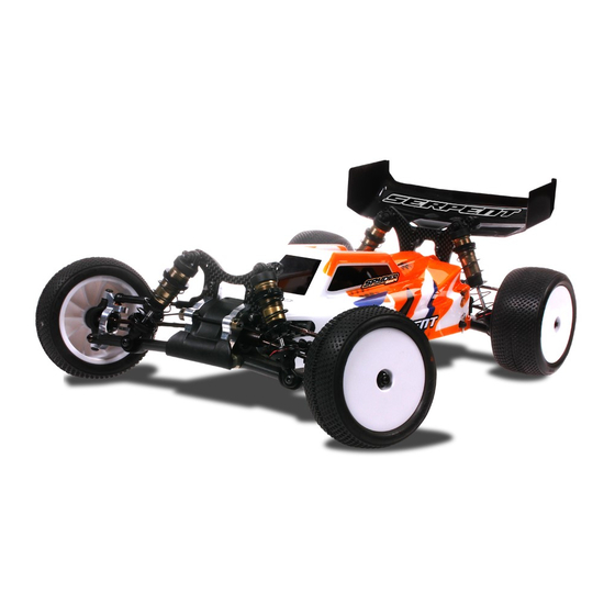
Summary of Contents for Serpent spyder SDX4
-
Page 2: Table Of Contents
REaD ThIS fIRST! The Serpent Spyder SDX4 is a state of the art 1/10 scale 4wd buggy which will give you the true Serpent - This is a highly technical hobby product, intended to be used in a safe racing environment. This car racing experience. - Page 3 hOW TO USE ThE maNUal lINES DESCRIpTION ICONS DESCRIpTION Each step contains a variety of numbers, lines, and symbols. The numbers represent the order in Each step contains a variety of symbols described below. which the parts should be assembled. The lines are described below. Step number;...
-
Page 4: Front And Rear Diff Assembly
fRONT aND REaR DIff aSSEmBly STEp 1 STEp 2 DIff Bag Add just enough oil to cover the large gear before assembling Follow step 1 to 5 twice to assemble 2 diffs, 1 for the front and 1 for the rear. the small satellite gears and cross pins. - Page 5 STEp 3 STEp 4 STEp 5 Fill the differential with silicone oil 1 mm above the crosspin, Do not overtighten the screws. M2.5x10 do NOT overfill. Use the silicone oil supplied in the kit. For the There is always a gap between correct cst value please check the default setupsheet.
-
Page 6: Center Assembly
CENTER aSSEmBly STEp 6 Bag 1 For the correct assembly of the rear suspension bracket follow the next instructions: 1- Assemble M3x18 screws to align the suspension bracket. 2- Fix the camber bracket with the M3x6 screw. 3- Remove M3x18 screw and proceed with step 7. M3x6 M3x18 M3x6... - Page 7 STEp 7 M3x10 M3x18 M3x8 M3x6 M3x6 M3x8 M3x6 M3x6 M3x6 M3x8 M3x10 M3x18...
- Page 8 STEp 8 STEp 9 Nylock Nut M3 M3x8 M3x8 M3x8 M3x8 M3x18 M3x18 Nylock Nut M3 M3x8...
-
Page 9: Rear Assembly
REaR aSSEmBly STEp 10 STEp 11 The pivotballs are used to ensure the complete free movement of the wishbones with the minimum 11.1 M2.5x4 play. For assembling them correctly follow the next recommendations: 1- The M3 shims must be assembled always in the front side of the wishbones. 2- The front pivotballs should be fully tightened. - Page 10 STEp 12 STEp 13 Bag 2 13.1 5x10x4 REAR ANTI-SqUAT The rear suspension bracket can be used in two different positions to adjust the anti-squat angle from 3 to 1 degrees. 13.2 1 DEGREE 3 DEGREES M3x6 Note the correct assembly of the bevel gear.
-
Page 11: Rear Gearbox Assembly
REaR gEaRBOX aSSEmBly STEp 14 STEp 15 STEp 16-a Assemble the REAR diff. 10x12x0.1 10x15x4 10x12x0.1 COMPLETE REAR GEARBOX ASSEMBLY 10x15x4 M3x15 M3x18 M3x8 M3x15 M3x8 M3x18 10x15x4... - Page 12 STEp 16-B STEp 17 After assembling the bulkheads in the step 16 it is needed to adjust rear wishbones pivotballs to ensure the complete free movement of the wishbones with the minimum play. For assembling them correctly follow the next recommendations: 1- Unscrew the rear pivotballs to adjust the wishbone play to the minimum.
- Page 13 STEp 18 Bag 3 18.1 REAR DEFAULT WHEELBASE SHIMS 2x10 M2x5 5x13x4 5x13x4 18.2 Nylock Nut M3 2x10 M2x5 Nylock Nut M3 5x13x4...
- Page 14 STEp 19 STEp 20 REAR CAMBERLINK LENGTH 26.5 mm M3x10 REAR CAMBERLINK POSITION Nylock Nut M3 Nylock Nut M3 M3x10...
- Page 15 STEp 21 M3x10 M3x10...
-
Page 16: Front Assembly
fRONT aSSEmBly STEp 22 STEp 23 Bag 4 22.1 The pivotballs are used to ensure the complete free movement of the wishbones with the minimum play. For assembling them correctly follow the next recommendations: 1- The rear pivotballs should be fully tightened. -
Page 17: Front Gearbox Assembly
fRONT gEaRBOX aSSEmBly STEp 24 STEp 25 STEp 26 Bag 5 24.1 5x10x4 10x15x4 24.2 10x12x0.1 Assemble the FRONT diff. COMPLETE FRONT GEARBOX 10x12x0.1 ASSEMBLY 10x15x4 Note the correct assembly of the bevel gear. M3x8 M3x8 5x10x4 10x15x4... - Page 18 STEp 27-a STEp 27-B STEp 28 After assembling the front bulkheads in the step 27-A it is needed to adjust front wishbones pivotballs to ensure the complete free movement of the wishbones with the minimum play. For assembling them correctly follow the M3x3 next recommendations: 1- Disassemble the front bumper...
- Page 19 STEp 29 Bag 6 1- Place the caster shims in the bushings 29.1 29.2 3X5X1 2- Place the bushings and shims onto the casterblock. 3- Slide the steering block assembly onto the caster- 5x10x4 block and fix with the M3x12 screws. 2x10 M3x12 M2x5...
- Page 20 STEp 30 STEp 31 31.1 FRONT CAMBERLINK LENGTH 24 mm 31.2 M3x8 M3x8 3x5x1 Nylock Nut M3 FRONT CAMBERLINK POSITION 3x5x1 M3x8 Nylock Nut M3...
-
Page 21: Steering Assembly
STEERINg aSSEmBly STEp 32 STEp 33 Bag 7 32.1 STEERING ROD LENGTH 24 mm Nylock Nut M3 M3x6 Nylock Nut M3 32.2 M3x6 M3x6 M3x6 M3x6 Nylock Nut M3... - Page 22 STEp 34 STEp 35 M3x8 4x7x2.5 M3x8 4x7x2.5 M3x8 4x7x2.5 4x7x2.5 4X7X2.5 M3x8...
- Page 23 STEp 36 STEp 37 M3x5 M3x5 Check how many teeth your servo spline has (23, 24 or 3x5x1 25) and use the right lever. M3x8 3x5x1 M3x8 3x5x1 M3x8 M3x5 M3x5 3x5x1 M3x5 M3x5 M3x8 M3x5...
-
Page 24: Slipper Assembly
SlIppER aSSEmBly STEp 38 STEp 39 Bag 8 39.1 2x10 10x15x4 Flanged SLIPPER INITIAL SETTING 39.2 2x10 0.5 to 1 mm 10x15x4 Flanged 2x10 10x15x4 Flanged... - Page 25 STEp 40 REaR mOTOR CONfIgURaTION DEfaUlT fRONT mOTOR CONfIgURaTION OpTIONal MOTORMOUNT AND BULKHEAD POSITION The motormount and bulkhead can be used in two different positions to change the weight distribution. REAR FORWARD REAR MOTOR MOTOR FRONT REAR M3x8 M3x8 M3x8...
- Page 26 STEp 41 DRIVESHAFTS LENGTH 72 mm M4x4 SHORT 78 mm LONG In case of using the motormount and bulkhead in the forward position the SHORT driveshaft must be assembled in the FRONT and the LONG driveshaft must be assembled in the REAR.
- Page 27 STEp 42 42.1 REaR mOTOR CONfIgURaTION DEfaUlT fRONT mOTOR CONfIgURaTION OpTIONal M2.5x6 42.2 M3x6 M2.5x6 42.2 M3x6 M2.5x6 M3x6 M3x6...
- Page 28 STEp 43 43.1 STEERING LINK LENGTH 30 mm 43.2...
-
Page 29: Shocks Assembly
ShOCkS aSSEmBly STEp 44 STEp 45 Bag 9 fR ShOCkS / Bag 10 RR ShOCkS 44.1 45.1 Note the correct orientation of the shock spacers . 2.5x6x0.5 Use some silicone oil during the assembly. Nut M2 For the correct piston holes and size please check the default setupsheet. - Page 30 STEp 46 STEp 47 46.1 46.2 SHOCKS LENGTH: Measure the Assemble the spring and spring- cup (align correctly) to complete shock length fully extended. 1-Bleed: push the shock- 1- Fill up with sillicone oil the shock. FRONT REAR rod all the way in slowly, fully using the silicone to allow excessive oil to oil supplied in the kit.
- Page 31 STEp 48 STEp 49 Bag 11 M3x20 Do not overtighten or squash Do not overtighten or squash M3x20 bushing with the nut and note bushing with the M3 plastic nut. orientation of the lower shock M3 Plastic Nut Flanged pivot ball. M3x10 M3 Plastic M3x12...
-
Page 32: Final Assembly
fINal aSSEmBly STEp 50 REaR mOTOR CONfIgURaTION DEfaUlT fRONT mOTOR CONfIgURaTION OpTIONal To avoid the car to run backwards when using this configuration, there are 2 options: 1) Change the speedo setting to “REV” (= reverse), if your speedo allows this. Use double sided tape 2) If not take out both differentials and turn them 180 degrees. - Page 33 STEp 51 REaR mOTOR CONfIgURaTION DEfaUlT fRONT mOTOR CONfIgURaTION OpTIONal 51.1 51.1 Pinion is not included in the Pinion is not included in the kit. Assemble the proper kit. Assemble the proper pinion for your set-up. pinion for your set-up. M3x10 M3x10 51.2...
- Page 34 STEp 52 STEp 53 M3x12 M3x10 M3x10 M3x10 M3x10 M3x12 M3x10...
- Page 35 STEp 54 Nut M4 Flanged 1- Rims included in the kit. 2- Rubber tyres not included in the kit. 3- Be sure to glue your rubber tyres to the wheels using Cyanoacrylate glue. Nut M4 Flanged Nut M4 Flanged...
-
Page 36: Exploded Views
2- Before painting the body, apply the precut masking sheet elements to the inside of the body. Follow the cleaning & painting instructions supplied by the polycarbonate paint supplier you choose. 3- Apply the Serpent and Spyder logo-decals on the body and wing. Clip small... - Page 37 EXplODED VIEWS INDEX gEaR DIffS EXplODED VIEW SlIppER EXplODED VIEW fRONT aND REaR gEaRBOXES EXplODED VIEW CENTRal EXplODED VIEW TRaNSmISSION EXplODED VIEW REaR EXplODED VIEW fRONT EXplODED VIEW STEERINg EXplODED VIEW fINal EXplODED VIEW TEam SERpENT NETWORk...
- Page 38 gEaRDIff aND SlIppER EXplODED VIEW GEARDIFF SLIPPER 500608 SDX4 Geardiff set fr/rr 500579 SDX4 Slipper set 804395 110208 1470 500580 500290 500555 909520 500556 500158 110135 100222 500583 500557 500582 500582 500158 110208 500158 500582 500581 500557 500213 opt 500580 500214 opt 500215 opt 500552...
- Page 39 fRONT aND REaR gEaRBOXES EXplODED VIEWS 500590 500559 500561 500560 500561 500590 1344 1315 1315 500558 500558 1344 110458 110458 110458 500608 500608 1344 110458 500590 500559 500560 1344 110124 110124 500590...
- Page 40 CENTRal EXplODED VIEW 110402 500578 500599 500550 110124 500595 110124 500577 110124 500549 110124 500628 opt 500596 500547 110183 110122 110159 110159 110104 110122 110122 500628 Suspension bracket FR-RR plus 2 SDX...
-
Page 41: Rear Exploded View
REaR EXplODED VIEW 110109 110109 110109 500576 110402 500554 110116 500161 500601 500347 500554 500597 1310 110116 110116 500347 110402 401391 500597 1310 500616 opt 1340 500624 opt 500605 500617 opt 110116 500546 500618 401391 500619 opt 500545 500620 opt 1340 500545 110165... -
Page 42: Front Exploded View
fRONT EXplODED VIEW 1310 500553 110116 110116 500347 500347 110116 401391 500575 1310 110116 401391 110124 500601 500611 opt 500612 opt 110402 500613 500614 opt 500572 500615 opt 110112 802260 500625 opt 500572 500626 opt 500544 500497 500604 500602 500366 500566 110409 500602... - Page 43 STEERINg EXplODED VIEW 110108 110124 110108 110130 110130 500591 110118 110124 500588 500606 500587 500587 500574 401134 401134 500585 804337 500607 500584 401134 500585 110118 500584 110402 500586 500584 500602 500629 opt 500573 411253 804124 110108 804130 401134 500602 110122 500572 802260 110157...
- Page 44 ShOCkS EXplODED VIEW 500183 500183 110153 500174 FRONT 500363 500175 REAR 500178 500176 opt 500487 500372 500177 500179 opt 500487 500180 opt 500222 opt 500223 opt 500224 opt 500225 opt 500226 FRONT 500227 opt 500228 opt 500229 opt 500230 opt 500231 opt 500136 500232 REAR...
- Page 45 fINal EXplODED VIEW 1602 1602 500598 110112 110183 500360 500594 1606 500567 110452 110183 500568 500374 500435 500593 110129 401687 110452 500570 110129 110140 500146 500136 500137 110140 500136 1647 500137 110109 110112 110183 1647 500105 500146 110109 500152 110122 110452 500152 500621...
-
Page 46: Team Serpent Network
TEam SERpENT NETWORk SPYDER SDX4 SPARE PARTS www.serpent.com/500020/spares/ SPYDER SDX4 OPTIONALS PARTS www.serpent.com/500020/Optionals/ SERPENT TOOLS www.serpent.com/product/Tools/ SERPENT MERCHANDISING www.serpent.com/product/Merchandising/... - Page 47 SERPENT WEBSITE AND BLOG www.serpent.com www.teamserpent.com www.dragon-rc.com SERPENT PROMO PAGES http://promo.serpent.com SERPENT FACEBOOK GROUPS http://promo.serpent.com/indexfb.htm SERPENT ADVANCED MANUALS http://promo.serpent.com/sam/ SERPENT SOCIAL MEDIA www.facebook.com/SerpentMRC www.youtube.com/user/SerpentMRC www.twitter.com/SerpentMRC www.plus.google.com/+SerpentModelcars/posts www.weibo.com/teamserpent...
- Page 48 #81040 1 Manual SDX4...
Need help?
Do you have a question about the spyder SDX4 and is the answer not in the manual?
Questions and answers