Advertisement
Quick Links
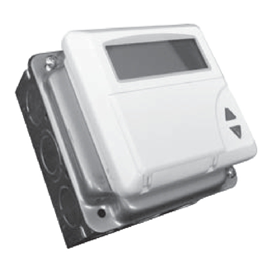
TC 204 Heating Controller
The TC204 is a multi-purpose heating controller with built-in programs for different types of heating systems.
General Data
Power requirement
24 volts ac, 25 va
Inputs
3 10k ohm ntc thermistors
1 digital
Outputs
3 digital
2 analog 0 - 10 volt dc
This manual covers outdoor reset of hot water heating systems using a mixing valve and a 3-point
floating actuator. For other applications see the expanded manual at www.paxtoncorp.com
Notes to the installer:
1. Program #1 - Outdoor reset control using a mixing valve, is the default program.
2. All defaults in program #1 will work in most cases.
3. Connect all sensors, the actuator wires and power supply. Set time & date (page 9)
and let the system stabilize, before making any program changes.
Nothing else needs to be done in most cases.
Wiring
The diagrams show ESBE #62E (Paxton VM62) & 92-2M (Paxton VM92) valve actuators . These are 3-wire
floating, 24 volt ac valve motors which fit ESBE 3-way & 4-way valves.
VM62 actuators are used with valve sizes 1/2" through 2": VM 92 actuators are used with valve sizes 2 1/2" - 6".
Actuators of this type have a common wire. Voltage applied between the common and one of the remaining wires
drives the valve open and voltage between the common the the remaining wire drives the valve closed. If no volt-
age is applied to either terminal the valve stays in place.
Other valves with different floating actuators may be used provided the voltage is 24 volts and the current draw
of the actuator does not exceed the capacity of the TC204 (25 VA). If these 2 conditions are not met the actuator
must be operated through intermediate relays.
Programs
There are eight programs in the TC204. This manual is for Program No.1 which is the default program.
Some not frequently used functions are not covered in this manual. Instructions for these as well as for all other
programs are available at:
Other programs provide outdoor reset by modulating valves that accept a 0 - 10 volt dc signal, outdoor reset by
direct boiler control, zone control without outdoor reset, and outdoor control of steam heating systems.
Program No. 1
Program 1 is Supply Water Temperature Control using a 3-point floating valve actuator. The control mode can be
Outdoor Reset with or without a room sensor, or direct control by room temperature only.
The supply temperature sensor must always be installed.
Outdoor reset is automatically initiated if the outdoor temperature sensor is installed.
Room temperature control is automatically initiated if the room temperature sensor is installed.
Additional functions are Pump Control, Auxiliary Output, and Return Water Low Limit (see page 8).
Temperature Sensors
The supply water and outdoor air temperature sensors are included with the TC204. A room temperature sensor
is optional. A room sensor is also built into the TC204, but to use it the TC204 must be installed in the controlled
space.
www.paxtoncorp.com
1
ver. 1.32-01
Advertisement

Summary of Contents for Paxton TC 204
- Page 1 Nothing else needs to be done in most cases. Wiring The diagrams show ESBE #62E (Paxton VM62) & 92-2M (Paxton VM92) valve actuators . These are 3-wire floating, 24 volt ac valve motors which fit ESBE 3-way & 4-way valves.
- Page 2 Notes: The TC 204 can be removed from the steel box cover and the external terminal board for installation directly in an occupied space. Loosen the connector on the circuit board and then the center screw under the lid of the controller.
- Page 3 Outdoor Reset Control with the VM62 Actuator. Black (counterclockwise) Brown (Clockwise) Blue (Common) VM62 Actuator Room or Return Sensor (Optional) Supply Water Sensor Outdoor Sensor If the valve turns in the wrong direction, reverse the brown & black wires on the VM62 actuator 24 Volts ac Power Sensor wires can be lengthened 25 va minimum...
- Page 4 VM92 Actuators Note: The 2 terminals marked L1 are not the same. The left one drives the actuator clock- wise and the right one drives the actuator N L1 L1 counter-clockwise. Output 2 on the TC204 increases heat. 1. Output to actuator – Less Heat 2.
- Page 5 TC204 Programming Instructions General There are 7 buttons. They are: Right & Left Step through values in a menu Set the Timer Select temperatures Inactive in Program 1 Up & Down Arrows Scroll through menus Clock and change values The time and date are set in the BASE menu. The clock stops after about 3 days without power and must be reset.
- Page 6 Menu 9 Valve Exercise MOT. 0 - 30 days Default 0 This line exercises the valve to keep it from sticking after a long period of inactivity. The valve periodically opens at 1:00 am and closes 3 minutes later. The line is inactive if it is set at “0”; otherwise the number is how often the event occurs: “1”...
- Page 7 Go to Menu 8 CURVE There are 3 adjustable values in this menu. Curve Design When you use a room sensor the reset curve is self adjusting. You need this section only if you donʼt use a room sensor and the default curve does not work for your region. - 10C1 32º...
- Page 8 Reset Curve Summary Function Menu Line Outdoor Cut-Off Temperature CUT.O Minimum Supply Temperature MIN W Maximum Supply Temperature MAX W Supply Temperature at 14º F -10C1 Supply Temperature at 50º F +10C1 220º 200º -10C1 180º MIN W 160º +10C1 140º...
- Page 9 Setting Room Temperatures Temperatures can be set with either the B key or in the BASE menu. Menu 1 BASE Press the key. You should see: TIMER Use this line to set the timer. Press the key again. DAY1 NITE1 SAVE1 These are room settings for the day, night, and long term setback mode. Even if you are not using room sensors, set these values.
- Page 10 Setting Times Times are set with a weekly program in which the Day, Night, and Economy cycles begin at set times on programmed days of the week. Optimized warm-up for the day cycle is also set in the Weekly Program. Date Programs, in which a cycle is programmed to begin and end on specific dates and hours, override the Weekly Program.
- Page 11 Optimization Menu 2 W.PR OPT1 0 - 40 Default 20 Skip this line initially. The colder it is outside and/or the further the room temperature is below set point the sooner the controller will start the warm-up cycle. The number in this line is a constant in the equation the TC204 uses to calculate the warm-up time.
- Page 12 The menus are: BASE Set the Date, Time, Temperatures, and Timer function. Readouts W.PR. Weekly Program There are 6 time periods that can be set to begin a day, night, or economy period. Each time can be set to begin on any day or combination of days of the week.
Need help?
Do you have a question about the TC 204 and is the answer not in the manual?
Questions and answers