Sony DSR-1800 Service Manual
Hide thumbs
Also See for DSR-1800:
- Service manual (468 pages) ,
- Operating instructions manual (120 pages) ,
- Brochure & specs (8 pages)
Table of Contents
Advertisement
Quick Links
DIGITAL VIDEOCASSETTE RECORDER
DSR-1800
DSR-1800P
DIGITAL VIDEOCASSETTE PLAYER
DSR-1600
DSR-1600P
SDI/AES/EBU INPUT/OUTPUT BOARD
DSBK-1801
SDTI (QSDI) INPUT/OUTPUT BOARD
DSBK-1802
i.LINK/DV INPUT/OUTPUT BOARD
DSBK-1803
SDI/AES/EBU OUTPUT BOARD
DSBK-1601
SDTI (QSDI) OUTPUT BOARD
DSBK-1602
SERVICE MANUAL
Volume 1 1st Edition
Advertisement
Table of Contents

Related Manuals for Sony DSR-1800


Summary of Contents for Sony DSR-1800
- Page 1 DIGITAL VIDEOCASSETTE RECORDER DSR-1800 DSR-1800P DIGITAL VIDEOCASSETTE PLAYER DSR-1600 DSR-1600P SDI/AES/EBU INPUT/OUTPUT BOARD DSBK-1801 SDTI (QSDI) INPUT/OUTPUT BOARD DSBK-1802 i.LINK/DV INPUT/OUTPUT BOARD DSBK-1803 SDI/AES/EBU OUTPUT BOARD DSBK-1601 SDTI (QSDI) OUTPUT BOARD DSBK-1602 SERVICE MANUAL Volume 1 1st Edition...
- Page 2 électrique, d’incendie ou de blessure n’effectuer que les réparations indiquées dans le mode d’emploi à moins d’être qualifié pour en effectuer d’autres. Pour toute réparation faire appel à une personne compétente uniquement. DSR-1800/1800P DSR-1600/1600P...
- Page 3 Mettre au rebut les batteries usagées conformément aux instructions du fabricant. ADVARSEL! Lithiumbatteri-Eksplosionsfare ved fejlagtig håndtering. Udskiftning må kun ske med batteri af samme fabrikat og type. Levér det brugte batteri tilbage til leverandøren. 1 (P) DSR-1800/1800P DSR-1600/1600P...
- Page 4 Klebestreifen ab oder geben Sie die Batterien einzeln in einen Plastikbeutel. Gooi de batterij niet weg. maar lever hem in als KCA. Bij dit produkt zijn batterijen geleverd. Wanneer deze leeg zijn, moet u ze niet weggooien maar inleveren als KCA. 2 (P) DSR-1800/1800P DSR-1600/1600P...
-
Page 5: Table Of Contents
Supplied Accessories .................. 2-2 2-6. Optional Accessories ................... 2-2 2-7. Rack Mounting .................... 2-3 2-8. Connectors....................2-5 2-8-1. Connectors/Cables (DSR-1800/P) ..........2-5 2-8-2. Connectors/Cables (DSR-1600/P) ..........2-6 2-8-3. Input/Output Signals of the Connectors ........2-7 2-9. Installation Setup and Adjustment ............2-10 2-9-1. - Page 6 Location and Function of Switches ..........5-3 5-2-2. How to Enter the Maintenance Menu ........5-3 5-2-3. How to Exit the Maintenance Menu .......... 5-3 5-3. Contents of Maintenance Menu ..............5-4 5-3-1. Menu Data Control ..............5-4 5-3-2. EDIT CHECK (DSR-1800/P) ............ 5-7 DSR-1800/P/1600/P...
- Page 7 7-13. TG1 Arm Assembly Replacement ............7-39 7-14. TG8 Arm Assembly Replacement ............7-41 7-15. Rail Assembly Replacement ..............7-43 7-16. Capstan Motor Replacement ..............7-49 7-17. Loading Motor Replacement..............7-51 7-18. Reel Shift Motor Assembly Replacement ..........7-52 7-19. MIC Assembly Replacement ..............7-54 DSR-1800/P/1600/P...
- Page 8 10-1-3. Reference Tape for Alignment ..........10-2 10-2. Audio Adjustment ..................10-4 10-2-1. Audio OUTPUT Level Adjustment ......... 10-4 10-2-2. Audio EE Level Adjustment (DSR-1800/P) ......10-4 10-3. Video Adjustment ..................10-5 10-3-1. INT SC Frequency Adjustment ..........10-6 10-3-2. HCK Frequency Adjustment ............ 10-6 10-3-3.
- Page 9 10-3-30. REC COMPOSITE Y/C Delay Adjustment (DSR-1800/P) .. 10-30 10-3-31. REC COMPONENT Y/C Delay Adjustment (DSR-1800/P) ................. 10-31 10-3-32. REC S VIDEO Y/C Delay Adjustment (DSR-1800/P) ..10-32 10-4. SDI/SDTI (Option Boards) ..............10-33 10-4-1. Free Run Adjustment ............. 10-33...
- Page 11 Purpose of this manual This manual is the Service Manual Volume 1 for the digital videocassette recorder DSR-1800/1800P and the digital videocassette player DSR-1600/1600P, the option boards SDI/AES/EBU Input/Output Board DSBK-1801, SDI/AES/EBU Output Board DSBK-1601, SDTI (QSDI) Input/Output Board DSBK-1802, SDTI (QSDI) Output Board DSBK-1602 and i.LINK/DV Input/Output Board DSBK-1803.
- Page 12 Section 8 Tape Path Alignment Describes the adjustment procedures of tape path system. Section 9 Electrical Alignment After Replacement Boards Describes the electrical adjustments after replacement boards. Section 10 Electrical Alignment Describes the electrical adjustment of each board. DSR-1800/P/1600/P V1...
- Page 17 POWER OVER OVER OVER OVER INPUT V:SDTI SDTI i.LINK VIDEO COMPOSITE Y-R,B S VIDEO SDI SG CH11/2 ANALOG AES/EBU SDI SG AUDIO CH23/4 ANALOG AES/EBU SDI SG PB FS 48k44.1k32k REC MODE 2CH4CH MARK...
- Page 21 (SUPER) DV IN/OUT SDTI(QSDI) DIGITAL AUDIO(AES/EBU) CH-1/2 CH-3/4 CH-1/2 CH-3/4 ANALOG VIDEO TIME CODE COMPONENT VIDEO OUT VIDEO IN S VIDEO COMPONENT VIDEO IN REF.VIDEO VIDEO OUT S VIDEO (SUPER) VIDEO CONTROL LEVEL LEVEL LEVEL LEVEL AUDIO IN AUDIO OUT MONITOR OUT HIGH HIGH...
- Page 22 CH-1/2 CH-3/4 CH-1/2 CH-3/4 LEVEL LEVEL LEVEL LEVEL AUDIO IN AUDIO OUT MONITOR OUT HIGH HIGH HIGH HIGH 600Ω 600Ω 600Ω 600Ω AUDIO CH-1 CH-2 CH-3 CH-4 CH-1 CH-2 CH-3 CH-4...
- Page 24 SAVE...
- Page 25 OVER OVER OVER OVER INPUT V:SDTI SDTI i.LINK VIDEO COMPOSITE Y-R,B S VIDEO SDI SG CH11/2 ANALOG AES/EBU SDI SG AUDIO CH23/4 ANALOG AES/EBU SDI SG PB FS 48k44.1k32k REC MODE 2CH4CH OVER OVER OVER OVER PB FS 48k44.1k32k OVER OVER OVER OVER...
- Page 27 OVER OVER OVER OVER INPUT V:SDTI SDTI i.LINK VIDEO COMPOSITE Y-R,B S VIDEO SDI SG CH11/2 ANALOG AES/EBU SDI SG AUDIO ANALOG AES/EBU SDI SG CH23/4 PB FS 48k44.1k32k REC MODE 2CH4CH OVER OVER OVER OVER PB FS 48k44.1k32k...
- Page 28 OVER OVER OVER OVER INPUT V:SDTI SDTI i.LINK VIDEO COMPOSITE Y-R,B S VIDEO SDI SG CH11/2 ANALOG AES/EBU SDI SG AUDIO CH23/4 ANALOG AES/EBU SDI SG PB FS 48k44.1k32k REC MODE 2CH4CH...
- Page 29 OVER OVER OVER OVER INPUT V:SDTI SDTI i.LINK VIDEO COMPOSITE Y-R,B S VIDEO SDI SG CH11/2 ANALOG AES/EBU SDI SG AUDIO CH23/4 ANALOG AES/EBU SDI SG PB FS 48k44.1k32k REC MODE 2CH4CH...
- Page 34 OVER OVER OVER OVER INPUT V:SDTI SDTI i.LINK VIDEO COMPOSITE Y-R,B S VIDEO SDI SG CH11/2 ANALOG AES/EBU SDI SG AUDIO ANALOG AES/EBU SDI SG CH23/4 PB FS 48k44.1k32k REC MODE 2CH4CH MARK...
- Page 37 OVER OVER OVER OVER INPUT V:SDTI SDTI i.LINK VIDEO COMPOSITE Y-R,B S VIDEO SDI SG CH11/2 ANALOG AES/EBU SDI SG AUDIO CH23/4 ANALOG AES/EBU SDI SG PB FS 48k44.1k32k REC MODE 2CH4CH OVER OVER OVER OVER INPUT V:SDTI SDTI i.LINK VIDEO COMPOSITE Y-R,B...
- Page 74 POWER OVER OVER OVER OVER PB FS 48k44.1k32k MARK...
- Page 77 SDI OUT AUDIO OUT(AES/EBU) SDTI(QSDI)OUT DV IN/OUT CH-1/2 CH-3/4 ANALOG VIDEO TIME AUDIO OUT MONITOR REF. VIDEO VIDEO S VIDEO COMPONENT VIDEO CODE AUDIO CH-1 CH-2 CH-3 CH-4 VIDEO CONTROL REMOTE (SUPER) ~AC IN...
- Page 78 AUDIO OUT MONITOR AUDIO CH-1 CH-2 CH-3 CH-4 AUDIO OUT(AES/EBU) CH-1/2 CH-3/4...
- Page 80 OVER OVER OVER OVER PB FS 48k44.1k32k...
- Page 81 OVER OVER OVER OVER PB FS 48k44.1k32k OVER OVER OVER OVER PB FS 48k44.1k32k...
- Page 86 OVER OVER OVER OVER PB FS 48k44.1k32k MARK...
- Page 87 OVER OVER OVER OVER PB FS 48k44.1k32k OVER OVER OVER OVER PB FS 48k44.1k32k...
-
Page 117: Installation Procedure
Section 2 Installation Be sure to install the DSR-1800/P/1600/P in location satisfying the required operational environment described below to assure the DSR-1800/P/1600/P superior performance and to maintain the excellent serviceability and accessibility. 2-1. Installation Procedure Start Determination of · · · 2-2. Operational Environment ·... -
Page 118: Installation Space
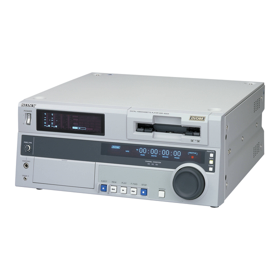
Note that it is not necessary to provide the space when the unit is mounted in a rack since the printed circuit boards can be repaired after it is pulled out. (33.7) DIGITAL VIDEOCASSETE RECODER DSR-1800 POWER REMOTE... -
Page 119: Rack Mounting
. Connect long enough cables on the connector panel, rail to the outside of the rack so that it meets the considering that the unit is pulled out. required specification. Outer menber L-angle Bracket W ER W ER W ER W ER L-angle Rack DSR-1800/P/1600/P... - Page 120 L-angles. Be sure to use the screws (B4 x 6) removed in step 3. Screws for L-angles are longer than ones for the side panels. Therefore, using the screws (PSW4 x 16) may cause trouble in the unit. DSR-1800/P/1600/P...
-
Page 121: Connectors
2-8. Connectors 2-8. Connectors 2-8-1. Connectors/Cables (DSR-1800/P) When external cables are connected to the connector on a connector panel during maintenance, the following (or equiva- lents) must be used. Connectors on DSR-1800/P Side Connector/Cable Panel indication Designation Sony Part No. -
Page 122: Connectors/Cables (Dsr-1600/P)
When external cables are connected to the connector on a connector panel during maintenance, the following (or equiva- lents) must be used. Connectors on DSR-1600/P Side Connector/Cable Panel indication Designation Sony Part No. ANALOG IN BNC, MALE 1-560-069-11 REF. VIDEO IN ANALOG OUT... -
Page 123: Input/Output Signals Of The Connectors
2-8. Connectors 2-8-3. Input/Output Signals of the Connectors INPUT (DSR-1800/P) BNC x2 (loop-through) REF.VIDEO : NTSC black burst, 0.286 V p-p, 75 Z, sync negative PAL black burst, 0.3 Vp-p , 75 Z sync negative VIDEO IN : BNC x2 (loop-through) Composite, 1.0 V p-p, 75 Z, sync negative... - Page 124 2-8. Maching Connectors OUTPUT (DSR-1800/P/1600/P) REF.VIDEO : BNC x1 NTSC composite sync, 0.286 V p-p, 75 Z, sync negative (with burst signal) PAL composite sync, 0.3 V p-p, 75 Z, sync negative (with burst signal) VIDEO OUT1, 2, 3(SUPER) : BNC x3 Composite, 1.0 V p-p, 75 Z, sync negative...
- Page 125 Y (G) RECEIVE A TRANSMIT A C (G) TRANSMIT B RECEIVE B Y (X) TRANSMIT COMMON RECEIVE COMMON C (X) PRIORITY IN PRIORITY OUT RECEIVE COMMON TRANSMIT COMMON RECEIVE B TRANSMIT B TRANSMIT A RECEIVE A FRAME GROUND FRAME GROUND DSR-1800/P/1600/P...
-
Page 126: Installation Setup And Adjustment
. In this case, video signal frame is delayed toward for audio signal. (2) SDTI/i.LINK button : SDTI (QSDI) ; Digital video/audio signal in SDTI (QSDI) format (DSBK- 1802 required) i.LINK ; Digital video and audio signals in i.LINK-compatible DV format (DSBK-1803 required) 2-10 DSR-1800/P/1600/P... - Page 127 (5) RESET (NO) : Used for the following purposes : . Initialization of the menu setting . “No” reply from the DSR-1800/P/1600/P to the inquiry. . COUNTER reset (on display block) (6) SET (YES) : Used for the following purposes : .
-
Page 128: On-Board Switch Setting
2-9. Installation Setup and Adjustment 2-9-3. On-board Switch Setting SSP-24 board (DSR-1800/P) S500 S400 SS-24 BOARD (A SIDE) Do not change the setting of switches when the “factory use” is shown in the description. Ref No. Description Factory Setting S400-1 HOURS METER can enter reset mode. -
Page 129: System Adjustment After Installation
. Adjust the SCH phase of this equipment to the system SCH with [SC PHASE] control on the sub control panel. . When this unit is connected to a switcher that does not have the sync switching function, the SYNC/ BURST level adjustment is required. DSR-1800/P/1600/P 2-13... -
Page 131: Location Of Main Parts
Section 3 Service Overview 3-1. Location of Main Parts 3-1-1. Location of Printed Circuit Boards DSR-1800/P/1600/P... - Page 132 MB-920 (DSR-1800/P) Mother board MB-927 (DSR-1600/P) DV-26 (DSBK-1803) i.LINK/DV input.output board (Option) SDI-61 (DSBK-1802) SDTI (QSDI) input.output board (Option : DSR-1800/P) SDI-61A (DSBK-1602) SDTI (QSDI) output board (Option : DSR-1600/P) SDI-62 (DSBK-1801) SDI/AES/EBU input.output board (Option : DSR-1800/P) SDI-62A (DSBK-1601)
- Page 133 3-1. Location of Main Parts Locations of Mechanism Deck Board Name Circuit Configuration SE-521 Mode sensor/tape end sensor/loading motor FG sensor SE-538 Tension sensor CN-1863 Sensor input/output board SE-525 LED signal board SE-522 Tape top sensor/reel position sensor (Mini/M/Standard) DR-428 Drum/mechanism control DSR-1800/P/1600/P...
- Page 134 Locations of Cassette Compartment Board Name Circuit Configuration CN-2021 Intermediate board between CC-84 and CC-83 CC-83 Cassette compartment mode detection/intermediate board CC-85 Cassette compartment cassette in detection CC-84 Cassette compartment cassette type detection CN-2022 Intermediate board between CC-85 and CC-84 DSR-1800/P/1600/P...
-
Page 135: Location Of Main Mechanical Parts
8 Brake solenoid @- Pinch roller 9 M stop solenoid assembly @= HC roller assembly !/ T brake assembly @[ Drum assembly !- MIC assembly @] Rail assembly != MIC holder assembly @\ Cassette compartment motor assembly ![ T reel motor DSR-1800/P/1600/P... -
Page 136: Location Of Sensors
Detects the top and end of a tape. 4 Condensation sensor The tension arm keeps the tension of a running tape Detects condensation occurred in DSR-1800/P/1600/P. constant during recording and playing. The tension 5 Tape top sensor sensor detects the mechanical position of the tension Detects the beginning of a tape that runs in the REV arm. - Page 137 2 The sensors PH1, PH2 and PH3 detect the movement of a cassette compartment by their combina- tion. 3 The sensors PH4 and PH5 detect that a mini cassette got inserted. The sensors PH4 and PH6 detect that a M cassette got inserted. The sensors PH4 and PH7 detect that a standard cassette got inserted. DSR-1800/P/1600/P...
-
Page 138: Functions Of Record Proof Hole And Record Proof Plug Of Cassette
Record proof hole Reel rotation stopper 4 3 2 1 Record proof plug Pin No. Function Equipped with built-in memory Not equipped with built-in memory Detecting tape thickness DATA Detecting tape type (Example: ME/MP) CLOCK Detecting tape application (Example: consumer/professional) DSR-1800/P/1600/P... -
Page 139: Removal/Installation Of Cabinet
Top panel Fixing screws (with stopper) Rear panel Claws B4 x 6 BV3 x 6 Claws Claws B4 x 6 Section A Claw Claws Left side panel Holes Claw Claw B4 x 6 B4 x 6 Right side panel DSR-1800/P/1600/P... - Page 140 (4) Detach the five claws of the rear panel from the holes of the chassis. (5) Reattach the rear panel in the reverse order of steps (1) to (4). 3-10 DSR-1800/P/1600/P...
- Page 141 (5) Insert the five knobs to the base. [Reference] [Reference] [Reference] [Reference] [Reference] Holes 3 x 6 If the knob easily comes off, widen the slot on the volume shaft using a flat tip screwdriver. PWH3 x 6 Claws Boss Front panel assembly 3-11 DSR-1800/P/1600/P...
-
Page 142: Removal/Reattachment Of The Cassette Compartment
(3) Reconnect the flexible card wire to the connector (CN1) of the CC-83 board. (4) Reattach the top panel. (Refer to Section 3-3.) Cassette compartment retainer assembly Fixing screws Fixing screw CC-83 board Cassette compartment Chassis Frexible card wire Positioning Positioning pin Positioning pins 3-12 DSR-1800/P/1600/P... -
Page 143: Removal/Reattachment Of The Boards
Attach the extension board to this unit and attach the board to be checked and adjusted to the top of the extension board. Extension board Card boards which can be connected DJ-498 SSP-24 (DSR-1800/P), IF-820 (DSR-1600/P), VPR-71 (DSR-1800/P), DPR-175 (DSR-1800/P), SSP-23 (DSR-1600/P) 3-13... -
Page 144: Removal/Reattachment Of The Boards
(2) Remove the card board. (Refer to Section 3-5-1.) (3) Pull out the claws of the duct from the square holes of the chassis, and remove the duct in the arrow direction. AC-212 board Harness (with INLET) Duct Chassis Claws Square holes 3-14 DSR-1800/P/1600/P... - Page 145 (2) Disconnect the CN4, CN10, CN11, CN3, CN19, CN20 CN302 and CN303 connectors from the DR-428 and CN21 connectors from the DR-428 board. board. (5) Disconnect the CN1 and CN2 connectors from the RP- 120 board (DSR-1800) or PRE-45 board (DSR-1600). DR-428 board CN10 CN17 Frame assembly, MD...
- Page 146 Positioning pin (2). (6) Reattach the front panel. Positioning pin B2 x 4 Positioning hole B2 x 4 Square holes DY-16 board Positioning hole DR-428 board B2 x 4 PWH 3 x 6 KY-484 board Flexible card wire 3-16 DSR-1800/P/1600/P...
- Page 147 Removal/Reattachment of the HP-108 board 78R board (DSR-1800/P) (1) Remove the front panel assembly. (1) Remove the DPR-175 board (DSR-1800/P)/SSP-23 (Refer to Section 3-3.) board (DSR-1600/P). (Refer to Section 3-5-1.) (2) Remove the two screws (BV3 x 6) securing the KY (2) Remove the two screws (PWH3 x 5) securing the FU- frame.
- Page 148 (7) Remove the nuts securing the HP VOL, HP jacks of Removal/Reattachment of the KY-484 board the HP-108 and remote controller jack, and remove the (DSR-1800/P)/484A board (DSR-1600/P) HP-108 board. (1) Remove the KY frame. (Refer to steps (1) to (6) of...
- Page 149 3-5. Removal/Reattachment of the Boards Removal/Reattachment of the MB-920 board (DSR-1800/P)/927 board (DSR-1600/P) MB-920 board (DSR-1800/P) CN202 MB-927 board (DSR-1600/P) CN301 (MB-920 board only) (1) Remove all the card boards. (Refer to Section 3-5-1.) (2) Disconnect the connectors (CN1, CN2, CN108,...
- Page 150 3-5. Removal/Reattachment of the Boards Removal/Reattachment of the RP-120 board (DSR-1800/P)/PRE-45 board (DSR-1600/P) (1) Set the frame assembly, MD in the vertical position. (Refer to Section 3-9-2.) (2) Disconnect the connectors (CN1 (RP-120 board only), CN2, CN3) of the RP-120 board/PRE-45 board.
- Page 151 (Refer to Section 7-18.) (12)Reattach the TG1 arm assembly. (Refer to Section 7-13.) P1.4 x 3.5 SE-521 board Square hole Claw of Positioning pin worm holder Flexible Flexible card wires card wire Square holes Positioning pin Flexible card wire 3-21 DSR-1800/P/1600/P...
- Page 152 (7) Reattach the SE-525 board in the reverse order of the removing steps (1) to (4). Tightening Torque : 0.1 N.m {1 kgf.cm} Claw LED holder assembly P1.4 x 2 Positioning hole SE-538 board Protruction Claw SE-525 board Rail assembly SE-525 board 3-22 DSR-1800/P/1600/P...
-
Page 153: Removal/Reattachment Of The Option Boards
Removal/Reattachment of the DV-26 (DSBK-1803) Boards board (1) Remove the DPR-175 board (DSR-1800/P)/SSP-23 . When removing, be sure to turn off the power first. board (DSR-1600/P). (Refer to Section 3-5-1.) . When attaching a new board, remove the screw (BV3 x (2) Remove the three screws (PWH3 x 5) securing the 6), and remove the blank panel. - Page 154 Removal/Reattachment SDI-61 board (DSBK- Removal/Reattachment SDI-62 board (DSBK- 1802)/61A board (DSBK-1602) 1801)/62A board (DSBK-1601) (1) Remove the DPR-175 board (DSR-1800/P)/SSP-23 (1) Remove the DPR-175 board (DSR-1800/P)/SSP-23 board (DSR-1600/P). (Refer to Section 3-5-1.) board (DSR-1600/P). (Refer to Section 3-5-1.) (2) Remove the three screws (PWH3 x 5) securing the (2) Remove the four screws (PWH3 x 5) securing the SDI-61/61A board.
-
Page 155: Notes On Repair Parts
Raise the portion marked “A” of the connector and release The following six types of flexible card wire are used in the lock. Pull out the flexible card wire. the DSR-1800/P/1600/P. Insertion method Take utmost care when handling the flexible card wires Insert the flexible card wire fully up to the marked line and because their life is extremely shortened by folding. - Page 156 Connect the flexible card wire after Flexible card wire checking for the correct side as shown. If the condition side and the insulation side are connected in the wrong direction, the circuit will not operate. Locked status 3-26 DSR-1800/P/1600/P...
- Page 157 Be careful that the flexible card wire is not slanted with respect to the connector. Flexible card wire Unlocked status Connector Connector Flexible card wire Locked status Flexible card wire Locked status 3-27 DSR-1800/P/1600/P...
-
Page 158: Replacement Of Lithium Battery
3-7. Replacement of Lithium Battery 3-7. Replacement of Lithium Battery Backup battery replacement procedure The SSP-24 board (DSR-1800/P) or SSP-23 board (DSR- When replacing the battery, insert the replacement battery 1600/P) board has the built-in lithium battery as the with the “+” and “_” ends correctly oriented. If the countermeasure for power failure. -
Page 159: Fixtures And Tools List
Brake torque gauge (CCW) (DJ-371) Brake torque adjustment J-6443-720-A (CW) Brake torque gauge (CW) (DJ-372) Brake torque adjustment J-6444-980-A Extension board (DJ-498) Extension board for DSR-1800/P/1600/P J-6444-610-B Path adjustment board (DJ-461) For tape path adjustment RF envelope detector fixture J-6444-720-A Path adjustment board... - Page 160 3-8. Fixtures and Tools list 2 3 4 9 !/ @/ @- @= 3-30 DSR-1800/P/1600/P...
-
Page 161: Servicing Positions Of The Frame Assembly, Md
Protrusion of the frame assembly, MD Hole Part A Claw of the frame assembly, MD Claw Part B Do not path adjustment and path checking in this position. There are after reattachment of the frame assembly, MD in regular position. 3-31 DSR-1800/P/1600/P... -
Page 162: Vertical Positions
(5) To return the frame assembly, MD to its original position, perform steps (1) to (4) in the reverse order. Claw of the frame Frame assembly, MD assembly, MD Claw Part A Frame assembly, MD Claw Part B Claw of the frame assembly, MD Part C 3-32 DSR-1800/P/1600/P... -
Page 163: Upgrading The System/Servo Cpu Program Version
3-10. Upgrading the System/Servo CPU Program Version 3-10. Upgrading the System/Servo CPU Program Version The DSR-1800/P/1600/P mounts the CPU for SY and SV on the SSP board and uses flash ROMs for loading this program. For re-writing flash ROMs, two methods are provided. -
Page 164: Version Upgrade From A Pc Through Rs-422
Operate in the order of “Select CPU.” → “ Designate hex.filename to be transferred.” → “Press Start button.”. During transferring, the status is displayed in between “PC Status” and “ Start, Cancel and Quit buttons”. The progress bar and the remaining time are displayed. 3-34 DSR-1800/P/1600/P... - Page 165 After the version upgrade is completed, turn off and on the power of the VTR. (In case of upgrading the same CPU or other CPU, it is not necessary to power down.) If properly finished, confirm that CPU versions written in the MAINTENANCE MENU are correct. 3-35 DSR-1800/P/1600/P...
-
Page 166: Upgrading The Fpga Program Version
3-11. Upgrading the FPGA Program Version 3-11. Upgrading the FPGA Program Version The DSR-1800/P/1600/P mounts the FPGA (field programmable gate alley) on the process board and uses flash ROMs for loading this program. The version of these flash ROMs mounted on the board can be upgraded using the following method. -
Page 167: Alarm Display
SETTING HAS BEEN CHANGED TO Detection : Checks the settings of switch DSR-1800 S400 on the SSP-24 board (DSR-1800/P)/SSP-23 board CHECK THE S400-5~8 (DSR-1600/P) and the con- SWITCH ON THE SS BOARD. tents of non-volatile memory (EEPROM). Operation after detection : None... - Page 168 SELECT I ONS OF THE SETUP MENU’S FACTORY USE Operation after detection : None I TEMS HAVE BEEN CHANGED. Display : The alarm is displayed until SET THESE I TEMS TO any key is pressed. FACTORY PRESET VALUES. DSR-1800/P/1600/P...
-
Page 169: Error Codes
EJECT mode. TAPE I S BE I NG EJECTED. The error code is displayed on the time counter. WA I T UNT I L TH I S I ND I CAT I ON GOES OFF. DSR-1800/P/1600/P... - Page 170 OF FOLLOW I NG CODE : The error code is displayed on the time counter. XX-XXX Perform Section “4-3-1. How to Take Out the Cassette Whose Tape is Slacked (MANUAL EJECT) ” when a cassette tape cannot be ejected with the emergency EJECT mode. DSR-1800/P/1600/P...
-
Page 171: Display Of Previously Detected Error Codes
4-2. Error Codes 4-2-1. Display of Previously Detected Error Codes When the DSR-1800/P/1600/P detects an internal abnormality, the error code is memorized in EEPROM. (Excluding error code 9X-XXX) A maximum of 8 error codes detected previously, starting from the latest error code, can be displayed. -
Page 172: Main Codes And Sub Codes
5 : FG detected. 6 : Rotating direction error detected. 7 : Excessive tension detected. 8 : Abnormal current detected. 9 : The full top or full end of a tape cannot be released. A : Retry in progress (Unthreading and re-threading) DSR-1800/P/1600/P... - Page 173 4 : Reference track pulse of the record side (R-TRKT) 1 : System control main CPU 5 : Reference frame pulse of the record side (R-FLTT) (SSP-24 (DSR-1800/P)/SSP-23 (DSR-1600/P), IC501) 6 : Reference track pulse of the playback side (P-TRKD) 2 : Keyboard u-COM (KY-484, IC102)
-
Page 174: Error Codes
Failed to detect the T reel FG during search. Failed to detect the S and T reel FGs during search. Detected the abnormal direction of S and T reel rotation during search. Detected slack tape during PLAY and REC. DSR-1800/P/1600/P... - Page 175 Displayed until operates normally any key is after the error is pressed. solved. Failed to detect the capstan FG by the FG check during Cassette tape Displayed until the cassette tape insertion. will be ejected. next cassette is inserted. DSR-1800/P/1600/P...
- Page 176 Detected the abnormal current in the cassette up/down motor. AUTO OFF EJECT Displayed until the (Emergency EJECT) next cassette is Failed to complete the cassette down motion within the inserted. specified time. Failed to complete the cassette up motion within the specified time. 4-10 DSR-1800/P/1600/P...
- Page 177 Detected an abnormality of cassette compartment position EJECT sensor. Detected an abnormality of fan motor. Only error is displayed. Detected an abnormality of cassette top/end sensor LED. STOP PLAY, EJECT Detected an abnormality of tension sensor. AUTO OFF EJECT (Emergency EJECT) DSR-1800/P/1600/P 4-11...
- Page 178 SPCON detected abnormality in R-TRKT. SPCON detected abnormality in R-FLTT. The servo main microprocessor detected abnormality of P-FLTD. The servo sub microprocessor detected abnormality of P-TRKD. The servo main microprocessor detected abnormality of R-FLTD. The servo sub microprocessor detected abnormality of R-TRKD. 4-12 DSR-1800/P/1600/P...
- Page 179 Track pair communication error between SPCON and A1R Rear. Communication error between SPCON and AIF-INDI. Communication error between SPCON and ACTL. Communication error between SPCON and REC-DSP. Communication error between SPCON and PB-DSP. Communication error between SPCON and OUT-DSP. DSR-1800/P/1600/P 4-13...
-
Page 180: Possible Causes Of Errors
↓ When a cassette compartment is lock after it is exchanged, the trouble is caused by the cassette compartment. Otherwise the trouble is caused by cassette compartment the defective drive circuit. DR-428 board 4-14 DSR-1800/P/1600/P... - Page 181 . S and T reel FG amp is defective. as intended. 6. Tension regulator is defective. Check the magnet position in the tension adjust SSP-24 board (DSR-1800/P)/ menu. SSP-23 board (DSR-1600/P), Confirm that OK appears on display. SE-538 board, DR-428 board 7.
-
Page 182: Countermeasure In An Emergency
(6) Turn the manual eject gear B (red) in the arrow Bamboo skewer Reel table (T) direction until the cassette compartment completely comes into cassette out state. Manual eject gear A (red) 4-16 DSR-1800/P/1600/P... -
Page 183: Head Cleaning When Head Clogging Occurs
The pinch roller is pressed against the capstan shaft to set REV.SEARCH to five-times speed. . Never move the cleaning cloth in the vertical direction against the video head because it may break the head. . Turn the power switch off when cleaning the video head. DSR-1800/P/1600/P 4-17... - Page 184 Reel position will be changed as shown below in accor- dance with the number of pressing the switch. Mini Make sure to turn off switches S400-4 on the SSP-24 board (DSR-1800/P)/SSP-23 board (DSR-1600/P) after the adjustment. 4-18 DSR-1800/P/1600/P...
-
Page 185: Menu Structure
Contents of the maintenance menu are displayed on the video monitor connected to the VIDEO OUT 2 (SUPER) connector or the SDI OUTPUT 2 (SUPER) connector and the time counter of DSR-1800/P1600/P. Values in parenthesis ( ) are time counter display. - Page 186 MEMORY DISPLAY (>MEM Check) SY MEMORY DISPLAY (>> SY MEM.) SV MEMORY DISPLAY (>> SV MEM.) SP MEMORY DISPLAY (>> SP MEM.) KY MEMORY DISPLAY (>> KY MEM.) CM DISPLAY (>> CM DISP.) DATA DISPLAY (>Data Check) SP DATA DISPLAY (>>SP DATA) DSR-1800/P/1600/P...
-
Page 187: How To Operate Maintenance Menu
5-2-2. How to Enter the Maintenance Menu 1. While pressing the [&] key, press the [MENU] key. The DSR-1800/P1600/P enters the maintenance menu. The maintenance menu appears on the video monitor. 2. Select the desired item using the [(] key and the [)] key. The cursor shown with a white background moves to the selected item. -
Page 188: Contents Of Maintenance Menu
5. When an item is selected, press the [*] key. The contents of the selected item appear. 6. Press the [&] key to exit MENU DATA CONTROL and return to the main menu. 7. Press the [MENU] key to exit the maintenance menu. DSR-1800/P/1600/P... - Page 189 EEPROM in the DR-428 board. . When the SET UP MENU is upgraded by ROM’s version upgrade, an alarm message appears after the ROM is replaced. Either initialize the SET UP MENU or execute “LOAD MENU DATA” when the alarm appears. DSR-1800/P/1600/P...
- Page 190 Pressing the [MENU] key returns to the main menu. In the case of trouble : Loading of the data will not start if SET UP MENU data has not been saved or the saved SET UP MENU data contains an error. DSR-1800/P/1600/P...
-
Page 191: Edit Check (Dsr-1800/P)
5-3. Contents of Maintenance Menu 5-3-2. EDIT CHECK (DSR-1800/P) 5-3-2. EDIT CHECK (DSR-1800/P) Enables the editing function to be checked without using a remote controller. Operating procedure 1. Enter the maintenance menu. MAINTENANCE MENU MENU DATA CONTROL 2. Move the cursor to “EDIT CHECK” which is displayed with a EDIT CHECK white background using the [(], [)] keys. - Page 192 5-3. Contents of Maintenance Menu 5-3-2. EDIT CHECK (DSR-1800/P) Enables the MANUAL EDIT by selecting each mode. [VIDEO|INSERT] Pressing the [REC] and [PLAY] keys simultaneously enters the VIDEO INSERT mode. [A1|INSERT] Pressing the [REC] and [PLAY] keys simultaneously enters the AUDIO CH-1 INSERT mode.
-
Page 193: Servo Check
10. To check other menus and submenus, repeat steps 4 to 9. 11. Press the [MENU] key to exit the maintenance menu. If the [MENU] key is pressed while the check is in progress, the check operation is forcibly ended and the display returns to the main menu. DSR-1800/P/1600/P... - Page 194 The respective items of “SENSOR CHECK” are described below : 1 CASS-COMPARTMENT Checks the respective switches of the cassette compartment. SW/Sensor Applicable board CC-85 CC-84 CC-84 board CC-85 board 1. Execute the CASS-COMPARTMENT. 2. Confirm that the sensors are all OFF with no cassette inserted. 5-10 DSR-1800/P/1600/P...
- Page 195 5. Insert the standard cassette and confirm that the status of the sensor is the monitor display shown right. 6. Insert the M-ADPT (Cassette adaptor for DVCPRO) and confirm that the status of the sensor is the monitor display shown right. * _ _ : not care DSR-1800/P/1600/P 5-11...
- Page 196 [OFF] on the monitor display. In the case of trouble : If the display does not change check whether the tape-top sensor or the tape-end sensor itself is defective. Check also the tape-top/tape-end sensor circuit (DR-428, SE-521/ 522 board). 5-12 DSR-1800/P/1600/P...
- Page 197 30 minutes to detect [DRY]. In the case of trouble : If the display does not change from DRY to WET!, check whether the HUMID sensor itself is defective. Check also the HUMID sensor amplifier (DR-428 board). DSR-1800/P/1600/P 5-13...
- Page 198 2. Confirm the monitor display is as shown right. 3. Press the REC INHIBIT switch. Confirm that ON is displayed on the monitor display. In the case of trouble : If OFF is not displayed, check the sensor on the MIC arm. 5-14 DSR-1800/P/1600/P...
- Page 199 If the brake solenoid does not emit the operating sound and the T reel motor does not rotate in the specified direction even though pressing the [(] and [)] keys, check the T reel motor assembly and reel motor driver circuit (DR-428 board). DSR-1800/P/1600/P 5-15...
- Page 200 SSP-24 (DSR- 1800/P)/SSP-23 board (DSR-1600/P). Check also the DR-428 board (the driver circuit and the threading FG amplifier circuit) and the SE-512 board (the sensor). 5-16 DSR-1800/P/1600/P...
- Page 201 In the case of trouble : If the monitor display does not change, check the cassette compartment motor, the SSP-24 (DSR-1800/P)/SSP-23 board (DSR-1600/P) (the sensor input circuit) and the CC-83 board (the sensor).
- Page 202 3. Press the [*] key again. Confirm that [REVERSE ... OK] appears on the monitor display. In the case of trouble : If the monitor display does not change, check the capstan motor and the capstan motor driver circuits (the DR-428 board). 5-18 DSR-1800/P/1600/P...
- Page 203 PG : [EXIST] In the case of trouble : If the monitor display does not change, check the drum motor, the DR-428 board (the drum motor driver circuit, the drum FG amp circuit and the drum PG amp circuit). DSR-1800/P/1600/P 5-19...
- Page 204 If the reel table does not move or the monitor display does not change, check the reel position motor, the reel MINI/M/STD position sensor (the SE-522 and DR-428 boards) and reel position motor driver circuit (the DR-428 board). 5-20 DSR-1800/P/1600/P...
- Page 205 Doing so, the monitor display returns to the main menu. In the case of trouble : If the pinch solenoid does not operate, check the pinch solenoid and the driver circuit (the DR-428 board). DSR-1800/P/1600/P 5-21...
- Page 206 6. Power off the unit, and connect the flexible card wire to cassette compartment. In the case of trouble : If the M plunger solenoid does not operate, check the M plunger solenoid and its driver circuit (the DR-428 board). 5-22 DSR-1800/P/1600/P...
-
Page 207: Servo Adjust
8. To check other menus and submenus, repeat steps 4 to 7. 9. Press the [MENU] key to exit the maintenance menu. If the [MENU] key is pressed while the adjustment is in progress, the adjustment operation is forcibly ended and the display returns to the main menu. DSR-1800/P/1600/P 5-23... - Page 208 In the case of trouble : When “ADJUST INCOMPLETE” appears on the monitor display, check the DR-428 board (the reel FG amplifier circuit, the reel motor driver circuit) and the S-reel motor. 5-24 DSR-1800/P/1600/P...
- Page 209 2. After completing adjustment, confirm that “COMPLETE” appears. Adjustment item capstan fg adjust In the case of trouble : When “ADJUST INCOMPLETE” appears on monitor display, check the DR-428 board (the capstan motor driver circuit, the capstan FG amplifier circuit) and the capstan motor. DSR-1800/P/1600/P 5-25...
- Page 210 3. Enter “MAINTENANCE MENU” and select “TENSION” from “SERVO ADJUST” using the [(], [)] keys. 4. Press the [*] key to move to the next display. 5. When the display appears, press the key to start the adjustment. 5-26 DSR-1800/P/1600/P...
- Page 211 Press the [STOP] key. 8. Keep pressing the [(], [)] keys until the DV torque cassette reading agrees with the specification value on display. 9. When adjustment is completed, press the [*] key. Specification is as indicated on the display. DSR-1800/P/1600/P 5-27...
- Page 212 5-3. Contents of Maintenance Menu 5-3-4. Servo Adjust 10. The display changes as shown in the right, and the DSR-1800/ P/1600/P enters the tension regulator magnet position check mode. 11. If the check is completed unsatisfactorily, the display changes as shown in the right.
- Page 213 20. Press the [EJECT] key and remove the DV torque cassette. 21. Confirm that the message “COMPLETE” appears on the display. Press the [EJECT] key to return to the ADJUST menu. When adjustment is complete, attach the cassette compartment. DSR-1800/P/1600/P 5-29...
-
Page 214: Tape Path Adjust
5-3-5. Tape Path Adjust 5-3-5. Tape Path Adjust Executes the adjustment of the tape path. (1) TRACKING ADJUST For adjustment of “TRACKING ADJUST”, refer to section 8-2. (2) RF SWITCHING POSITION For adjustment of “RF SWITCHING POSITION”, refer to section 8-3. 5-30 DSR-1800/P/1600/P... -
Page 215: Electrical Adjust
“ELECTRICAL ADJUST” is selected and its lower-layer submenu appears. 4. Move the cursor displayed with a white background to a desired item using the [(] and [)] keys. 5. Press the [*] key to select the desired item. DSR-1800/P/1600/P 5-31... - Page 216 3. Press the [&] key to return to the ADJUST menu. 4. Press the [MENU] key to exit the maintenance menu. In the case of trouble : If “INCOMPLETE” appears on the monitor display, check the RP-120 board (DSR-1800/P)/PRE-45 board (DSR-1600/P) (the PLL circuit). 5-32 DSR-1800/P/1600/P...
- Page 217 If “INCOMLETE” is displayed on the monitor; 1 Send the small length of the tape forward and repeat step 2 again. 2 If “INCOMLETE” is still displayed after performing 1, check the RP-120 board (DSR-1800/P)/PRE-45 board (DSR- 1600/P) (the EQ circuit). DSR-1800/P/1600/P 5-33...
- Page 218 If “INCOMLETE” is displayed on the monitor; 1 Send the small length of the tape forward and repeat step 2 again. 2 If “INCOMLETE” is still displayed after performing 1, check the RP-120 board (DSR-1800/P)/PRE-45 board (DSR- 1600/P) (the EQ circuit). 5-34 DSR-1800/P/1600/P...
- Page 219 Main E → Main O 7. Confirm that the DATA on the screen is 0000* through 000F*. 8. Pressing the [MENU] key return to the main menu. If press the key during confirmation, perform the EQ AUTO adjustment.5 DSR-1800/P/1600/P 5-35...
- Page 220 5-3. Contents of Maintenance Menu 5-3-6. Electrical Adjust 4. REC CURRENT 1. Selected the REC CURRENT. 2. Press the [(], [)] keys and the [&], [*] keys to adjust the data to “C0”. 3. Press the key to save the data. 5-36 DSR-1800/P/1600/P...
- Page 221 (Press the keys in this order : [HOLD], keys, to set the time counter to 00, which facilitates the operation.) 2. Connect an oscilloscope as follows : Check : TP301 & TP401/RP-120 board (DSR-1800/P) GND : E300 & E401 TRIG : TP300 3. Select the FE CHECK.
- Page 222 4. After completing the adjustment, the display returns automati- CONTROLLER. cally to the maintenance menu. DATA SET SET KEY ABORT MENU KEY 7. PROCESS CHECK This menu is for the factory use only. 8. REF CHECK This menu is for the factory use only. 5-38 DSR-1800/P/1600/P...
- Page 223 2. As “RP DATA INITIALIZE” will be displayed on the screen, press the key when initializing the adjusted data. After initialization, be sure to perform the following three adjustments in Section “5-3-6. Electrical Adjust.” 1. PLL F0 2. EQ AUTO ADJ 4. REC CURRENT DSR-1800/P/1600/P 5-39...
-
Page 224: Service Support
6. After completing the check, press the [MENU] key to return to the main menu. 7. To check other menus and submenus, repeat steps 4 to 6. 8. Press the [MENU] key to exit the maintenance menu. 5-40 DSR-1800/P/1600/P... - Page 225 2. MANUAL EJECT For the operating procedure of how to take out a tape when the EJECT is inoperable, refer to section 4-3. 3. DIAGNOSTICS CONTROL 1 CLEAR ERROR LOG Clears the error history from the ERROR LOG. DSR-1800/P/1600/P 5-41...
-
Page 226: Dsbk
6. After completing the check, press the [MENU] key to return to the main menu. 7. To check other menus and submenus, repeat steps 4 to 6. 8. Press the [MENU] key to exit the maintenance menu. 5-42 DSR-1800/P/1600/P... -
Page 227: Dsbk
(When DSBK-1803 is installed.) The message NONE appears for the DVIO, SDI, DIF and AIFI when the optional board is not installed in the DSR-1800/P1600/ Contents which are shown in the time counter display can be changed using the [(], [)]keys. -
Page 228: Dsbk
TO MENU : MENU KEY The message NONE appears for the DVIO, SDI and DIF when the optional board is not installed in the DSR-1800/P1600/P. Contents which are shown in the time counter display can be changed using the [(], [)]keys. -
Page 229: Periodic Inspection List
Item Part No. Name Menu No. 2000 4000 6000 8000 Drum assembly A-8327-026-A DEH-19A-R (For DSR-1800/P) T2 A-8327-027-A DEH-20A-R (For DSR-1600/P) T2 Tape drive system blocks Pinch solenoid A-8279-203- Pinch Solenoid assembly Brake solenoid 1-454-930-11 Solenoid plunger Reel motor (T) -
Page 230: Hours Meter
(except for the still mode during search) CT : THREADING Numbers of times of threading and unthreading Example : The following display indicates that the accumulated hours of drum rotation at the threaded-end position is 1500 hours. DSR-1800/P/1600/P... - Page 231 VIDEO IN SDTI/i.LINK COUNTOR SEL INPUT SELECT MOUNTER SELECT CH-1,1/2 MENU RESET(NO) SYNC PHASE SC PHASE SET(YES) CH-2,3/4 TC PRESET DSR-1800/P MENU SET(YES) COUNTOR SEL MOUNTER SELECT MENU RESET(NO) SYNC PHASE SC PHASE SET(YES) DSR-1600/P MENU SET(YES) 1. Press the [MENU] key.
- Page 232 6-2. Hours Meter 3. How to Reset 1. DSR-1800/P ; S400-1 on the SSP-24 board to ON. DSR-1600/P ; S400-1 on the SSP-23 board to ON. 2. Press the [MENU] key. 3. Select HOURS METER using [(], [)] keys. 4. Select the desired item to reset using [(], [)] keys.
-
Page 233: Maintenance Upon Completion Of Repair
. Never move the cleaning cloth in vertical direction with respect to the drum rotation (up and down with respect to the drum) during cleaning. . After cleaning, wipe off moisture using a dry cleaning cloth. . Turn off the main power before cleaning a unit. DSR-1800/P/1600/P... -
Page 234: Cassette Compartment Entrance Cleaning
Clean the rear block of the cassette guide assembly with a cleaning cloth moistened with a cleaning fluid. Rear block of the cassette guide assembly Cassette guide area (cleaning) prevent foreign materials from dropping into a unit. Front panel block DSR-1800/P/1600/P... -
Page 235: General Information On Parts Replacement And Adjustment
DSR-1800/P/1600/P not so far as specified. (Refer to section 3-4.) . When the connector of the cassette compartment is removed, the protection circuit starts functioning. Refer to section “4-3-3. Operating the VTR without a Cassette Tape.” to operate the DSR-1800/P/1600/ P without the cassette compartment. -
Page 236: Tightening Torque And Handling Of Washers
[Reference] [Reference] DSR-1800/P/1600/P uses many small screws that easily fall inside the machine when removing and re- assembling parts. To avoid this risk, magnetize the screwdriver bit slightly enough to prevent small screws from falling into the machine. However, when installing the drum assembly, never use a magnetized screwdriver. -
Page 237: Drum Replacement
3. Remove the top plate. (Refer to Section 3-3.) 4. Remove the cassette compartment assembly. (Refer to Section 3-4.) Tool . Cleaning cloth : 3-184-527-01 . Cleaning fluid : 9-919-573-01 . Torque screwdriver bit (for M1.4) : J-6325-110-A . Torque screwdriver (for 3 kgf.cm) : J-6325-400-A DSR-1800/P/1600/P... - Page 238 BV3 x 6 (2) Disconnect the connectors (CN301, CN302) of the DR-428 board, and connectors (CN200, CN201, CN202 (RP-120 board only) of the PR-120 board (DSR-1800)/PRE- Part A 45 board (DSR-1600), and remove the frame assembly, MD. 2. Disconnecting the connectors...
- Page 239 Positioning pin Cleaning (4) While moving the drum assembly in the direction of the arrow (counterclockwise Hole direction), tighten the three screws in the order of a, b, c. Tightening torque : 0.1 N.m {1 kgf.cm} Positioning pin Installation surface DSR-1800/P/1600/P...
- Page 240 Frame assembly, MD (CN12) on the DR-428 board, and flexible card wires to the connectors (CN1 (RP-120 board only, CN2) on the RP-120 board (DSR-1800/P)/ PRE-45 board (DSR-1600/P). DR-428 board . Be careful not to insert the flexible card wire obliquely.
- Page 241 DR-428 board, and connectors (CN200, CN301 CN302 Frame assembly, MD CN201, CN202 (RP-120 board only) of the CN202 CN201 PR-120 board (DSR-1800)/PRE-45 board BV3 x 6 CN200 (DSR-1600). BV3 x 6 (2) Insert the bosses of the front panel into the holes of the frame assembly, MD, and align the positioning pin and positioning hole.
-
Page 242: S/T Brake Assembly Replacement
. Torque screwdriver’s bit (for M2) : J-6325-380-A . Torque screwdriver (for 3 kgf.cm) : J-6325-400-A . Washer extracting fixture (A) : J-6082-234-A . Washer mounting fixture Ø1.5 : J-6082-231-A . Cleaning cloth : 3-184-527-01 . Cleaning fluid : 9-919-573-01 . Tweezers DSR-1800/P/1600/P... - Page 243 (Refer to Section 7-19.) 5. Removing the reel cover P1.4 x 3 Remove the screw, and then release the two claws to remove the reel cover S or T. Reel cover S P1.4 x 3 Reel cover T Claw Claw Claw Claw DSR-1800/P/1600/P...
- Page 244 . If the torque is high, hook the brake spring on the c portion. . If the torque is low, hook the brake spring on the a portion. 7-10 DSR-1800/P/1600/P...
- Page 245 L push plate aligned with the two protrusions on the RLR assembly. Tightening Torque : 0.1 N.m {1 kgf.cm} 11. Reattaching the frame assembly, MD Reattach the frame assembly, MD. (Refer to Section 7-2 Step 7.) Protrusion 7-11 DSR-1800/P/1600/P...
-
Page 246: Brake Solenoid Replacement
. Torque screwdriver’s bit (for M1.4) : J-6325-110-A . Torque screwdriver’s bit (for M2) : J-6325-380-A . Torque screwdriver (for 3 kgf.cm) : J-6325-400-A . Washer extracting fixture (A) : J-6082-234-A . Washer mounting fixture Ø1.5 : J-6082-231-A . Tweezers 7-12 DSR-1800/P/1600/P... - Page 247 Brake assembly pulled in direction. (3) Pull out the harness of the solenoid from the square hole in the left side of the chassis with P1.4 x 3.5 the brake assembly lifted up. Harness Chassis Hole CN15 7-13 DSR-1800/P/1600/P...
- Page 248 Brake base pin screw locking compound. Tightening Torque : 0.5 N.m {5 kgf.cm} (9) Reattach the brake slider assembly to the brake base assembly with a new stop washer. 7-14 DSR-1800/P/1600/P...
- Page 249 (2) Following the pop-up menu in the mainte- nance menu, enter SERVO CHECK, PLUNGER CHECK, REEL BRAKE in order and select REEL BRAKE. (3) Check that the brake solenoid ON/OFF switches smoothly by presing the [AUDIO|IN] key and the [IN] key. 7-15 DSR-1800/P/1600/P...
-
Page 250: Pinch Roller Replacement
4. Remove the cassette compartment. (Refer to Section 3-4.) Tools . Washer extracting fixture (A) : J-6082-234-A . Washer mounting fixture Ø1.5 : J-6082-231-A . Cleaning cloth : 3-184-527-01 . Cleaning fluid : 9-919-573-01 . Grease (SG-941) : 7-662-001-39 . Tweezers 7-16 DSR-1800/P/1600/P... - Page 251 MD chassis, while fitting the slotted hole in the pinch limiter assembly on the shaft on the pinch solenoid assembly, and fix it with a new stop washer (1.5). Adjustment after replacement 3. Checking the tape path adjustment (Refer to Section 8-4.) 7-17 DSR-1800/P/1600/P...
-
Page 252: Elevator Cam Replacement
4. Remove the cassette compartment. (Refer to Section 3-4.) Tools . Washer extracting fixture (A) : J-6082-234-A . Washer mounting fixture Ø1.5 : J-6082-231-A . Cleaning cloth : 3-184-527-01 . Cleaning fluid : 9-919-573-01 . Grease (SGL-941) : 7-662-001-39 . Tweezers 7-18 DSR-1800/P/1600/P... - Page 253 (7) Fit the compressed coil spring on the shaft. Intermittent portion 3. Reattaching the pinch limiter No.7 gear assembly Reattach the pinch limiter assembly. (Refer to Section 7-5.) Adjustment after replacement 4. Checking the tape path adjustment. (Refer to Section 8-4.) 7-19 DSR-1800/P/1600/P...
-
Page 254: Pinch Solenoid Assembly Replacement
4. Remove the cassette compartment. (Refer to Section 3-4.) Tools . Torque screwdriver’s bit (for M1.4) : J-6325-110-A . Torque screwdriver (for 3 kgf.cm) : J-6325-400-A . Washer extracting fixture (A) : J-6082-234-A . Washer mounting fixture Ø1.5 : J-6082-231-A . Tweezers 7-20 DSR-1800/P/1600/P... - Page 255 Reconnect the harness to the connector (CN20) on the DR-428 board with tweezers. 5. Reattaching the pinch limiter assembly Reattach the pinch limiter assembly. (Refer to Section 7-5.) Adjustment after replacement 6. Checking the tape path adjustment (Refer to Section 8-4.) 7-21 DSR-1800/P/1600/P...
-
Page 256: Reel Motor (T) Assembly Replacement
1. Set the unit to the unthreading end status after the unit to the standard cassette position. 2. Power off the unit. 3. Remove the top panel. (Refer to Section 3-3.) 4. Remove the cassette compartment. (Refer to Section 3-4.) 7-22 DSR-1800/P/1600/P... - Page 257 6. Removing the RMP (T1) retainer T drawer arm assembly assembly (1) Remove the screw (a) with the T-drawer arm assembly drawn lightly in the arrow direc- tion. (2) Remove the screw (b) and remove the RMP (T1) retainer assembly. 7-23 DSR-1800/P/1600/P...
- Page 258 (7) Insert the flexible card wire in the square hole in the MD chassis. (8) Tighten the screw a and next b to reattach the slide shaft. Tightening Torque : 0.1 N.m {1 kgf.cm} RS plate assembly Cleaning Square hole 7-24 DSR-1800/P/1600/P...
- Page 259 13. Reattaching the frame assembly, MD Reattach the frame assembly, MD. (Refer to Section 7-2 Step 7.) Adjustment after replacement 14. T-REEL ONLY adjustment (Refer to Section 5-3-3.) 15. TENSION adjustment (Refer to Section 5-3-3.) 16. Tape path adjustment (Refer to Section 8-2.) 7-25 DSR-1800/P/1600/P...
-
Page 260: Reel Motor (S) Assembly Replacement
4. Remove the cassette compartment. (Refer to Section 3-4.) Tools . Torque screwdriver’s bit (for M1.4) : J-6325-110-A . Torque screwdriver’s bit (for M2) : J-6325-380-A . Torque screwdriver (for 3 kgf.cm) : J-6325-400-A . Cleaning cloth : 3-184-527-01 . Cleaning fluid : 9-919-573-01 7-26 DSR-1800/P/1600/P... - Page 261 (1) Remove the screw (a) with the S tension regulator arm assembly drawn lightly in the arrow direction. (2) Remove the screw (b), then remove the RMP (S1) retainer assembly. Screw (a) P1.4 x 3.5 P1.4 x 3.5 RMP retainer (S1) assembly 7-27 DSR-1800/P/1600/P...
- Page 262 (7) Insert the flexible card wire in the square hole Slot in the MD chassis. (8) Tighten the screw a and next b to reattach RS plate assembly the slide shaft. Cleaning Tightening Torque : 0.1 N.m {1 kgf.cm} MD chassis 7-28 DSR-1800/P/1600/P...
- Page 263 9. Reattaching the frame assembly, MD Reattach the frame assembly, MD. (Refer to Section 7-2 Step 7.) Adjustment after replacement 10. S-REEL ONLY alignment (Refer to Section 5-3-3.) 11. TENSION alignment (Refer to Section 5-3-3.) 12. Tape path adjustment (Refer to Section 8-2.) 7-29 DSR-1800/P/1600/P...
-
Page 264: M Stop Solenoid Assembly Replacement
4. Remove the cassette compartment. (Refer to Section 3-4.) Tools . Torque screwdriver’s bit (for M1.4) : J-6325-110-A . Torque screwdriver’s bit (for M2) : J-6325-380-A . Torque screwdriver (for 3 kgf.cm) : J-6325-400-A . Screw locking compound : 7-432-114-11 7-30 DSR-1800/P/1600/P... - Page 265 (3) Extract the compressed coil spring from the iron core of the plunger solenoid removed in step (2) and fit the spring on a new solenoid Plunger solenoid iron core. Compression spring Iron core 7-31 DSR-1800/P/1600/P...
- Page 266 Tightening Torque : 0.2 N.m {2 kgf.cm} Hole for Hole for screw (7) Ensure the stopper driving plate returns to the screw original position after being pressed in the arrow direction and released. Plunger solenoid Notch Pins Screw locking compound 7-32 DSR-1800/P/1600/P...
- Page 267 (4) Reconnect the harness of the M stop solenoid to the connector (CN13) on the DR-428 Connector (CN13) board. 5. Reattaching the frame assembly, MD Reattach the frame assembly, MD. (Refer to Section 7-2 Step 7.) DR-428 board 7-33 DSR-1800/P/1600/P...
-
Page 268: S Tension Regulator Assembly Replacement
4. Remove the cassette compartment. (Refer to Section 3-4.) Tools . Torque driver’s bit (for M1.4) : J-6325-110-A . Torque driver (for 3 kgf.cm) : J-6325-400-A . Cleaning cloth : 3-184-527-01 . Cleaning fluid : 9-919-573-01 . Tweezers 7-34 DSR-1800/P/1600/P... - Page 269 The column pushes the spring under unthreading end status. Positioning pin Post of No.3 gear Unless satisfy these conditions, perform the step (2) and after. (7) Turn the manual eject cover counterclock- wise to bring to the unthreading end position. 7-35 DSR-1800/P/1600/P...
- Page 270 Wipe the tape guides of the S tension regulator and the TG1 arm assemblies with a cleaning cloth moistened with cleaning fluid. Adjustment after replacement 9. TENSION adjustment (Refer to Section 5-3-3.) 10. Tape path adjustment (Refer to Section 8-2.) 7-36 DSR-1800/P/1600/P...
-
Page 271: T Drawer Arm Assembly Replacement
1. Let the unit into the unthreading position. 2. Power off the unit. 3. Remove the top panel. (Refer to Section 3-3.) 4. Remove the cassette compartment. (Refer to Section 3-4.) Tools . Cleaning cloth : 3-184-527-01 . Cleaning fluid : 9-919-573-01 . Tweezers 7-37 DSR-1800/P/1600/P... - Page 272 Wipe the tape guide on the T drawer arm assem- Sleeve bly with a cleaning cloth moistened with cleaning No.6 gear fluid. T gear Adjustment after cleaning 5. Checking the tape path adjustment (Refer to Section 8-4.) T spring Grease Shaft Slit T gear MD chassis 7-38 DSR-1800/P/1600/P...
-
Page 273: Tg1 Arm Assembly Replacement
3. Remove the top panel. (Refer to Section 3-3.) 4. Remove the cassette compartment. (Refer to Section 3-4.) Tools . Torque screwdriver’s bit (for M1.4) : J-6325-110-A . Torque screwdriver (for 3 kgf.cm) : J-6325-400-A . Cleaning cloth : 3-184-527-01 . Cleaning fluid : 9-919-573-01 7-39 DSR-1800/P/1600/P... - Page 274 2. Cleaning the tape guide Wipe the tape guide on the TG1 arm assembly with a cleaning cloth moistened with cleaning fluid. Adjustment after replacement 3. TENSION adjustment (Refer to Section 5-3-3.) 4. Checking the tape path adjustment (Refer to Section 8-4.) 7-40 DSR-1800/P/1600/P...
-
Page 275: Tg8 Arm Assembly Replacement
. Torque screwdriver’s bit (for M1.4) : J-6325-110-A . Torque screwdriver (for 3 kgf.cm) : J-6325-400-A . Washer extracting fixture (A) : J-6082-234-A . Washer mounting fixture Ø1.5 : J-6082-231-A . Cleaning cloth : 3-184-527-01 . Cleaning fluid : 9-919-573-01 . Tweezers 7-41 DSR-1800/P/1600/P... - Page 276 2. Cleaning the tape guide Wipe the tape guide on the TG8 arm assembly with a cleaning cloth moistened with cleaning fluid. Adjustment after replacement 3. Adjustment after replacement Checking the tape path adjustment (Refer to Section 8-4.) 7-42 DSR-1800/P/1600/P...
-
Page 277: Rail Assembly Replacement
4. Remove the cassette compartment. (Refer to Section 3-4.) Tools . Torque screwdriver’s bit (for M1.4) : J-6325-110-A . Torque screwdriver (for 3 kgf.cm) : J-6325-400-A . Cleaning cloth : 3-184-527-01 . Cleaning fluid : 9-919-573-01 . Tweezers 7-43 DSR-1800/P/1600/P... - Page 278 (1) Disconnect the flexible card wire from the connector (CN2) on the SE-522 board. Use extreme care not to fold and not to scratch the flexible card wire when discon- necting. SE-522 board Connector (CN2) Flexible card wire 7-44 DSR-1800/P/1600/P...
- Page 279 Use extreme care not to scratch the drum and the tape guide when removing. Also great care should be taken; not to fold and not to scratch the flexible card wire of the LED holder assembly when disconnecting. Rail assembly Flexible card wire 7-45 DSR-1800/P/1600/P...
- Page 280 Shuttle (R) assembly Gear (5) Unlock each two claws located on the left, right and middle side of the LED holder assembly with tweezers, and remove the LED holder assembly from the rail assembly. Claw Claw LED holder assembly 7-46 DSR-1800/P/1600/P...
- Page 281 Shuttle (L) assembly far as it will go, and align the positioning hole of the shuttle (L) assembly with the positioning hole of the rail assembly. Rail assembly Gear Positioning hole Shuttle (L) asembly Rail plate Positioning hole 7-47 DSR-1800/P/1600/P...
- Page 282 . T drawer arm assembly . S tension regulator assembly . Shuttle (R) assembly . Shuttle (L) assembly Adjustment after replacement 14. TENSION adjustment (Refer to Section 5-3-3.) 15. Tape path adjustment (Refer to Section 8-2.) 7-48 DSR-1800/P/1600/P...
-
Page 283: Capstan Motor Replacement
3. Remove the top panel. (Refer to Section 3-3.) 4. Remove the cassette compartment. (Refer to Section 3-4.) Tools . Torque screwdriver’s bit (for M1.4) : J-6325-110-A . Torque screwdriver (for 3 kgf.cm) : J-6325-400-A . Cleaning cloth : 3-184-527-01 . Cleaning fluid : 9-919-573-01 7-49 DSR-1800/P/1600/P... - Page 284 6. Cleaning the Capstan shaft Wipe the capstan shaft with a cleaning cloth moistened with cleaning fluid. Adjustment after replacement 7. CAPSTAN ONLY adjustment (Refer to Section 5-3-3.) 8. Checking the tape path adjustment (Refer to Section 8-4.) 7-50 DSR-1800/P/1600/P...
-
Page 285: Loading Motor Replacement
(3) Fix the loading motor assembly with the two screws. Tightening Torque : 0.1 N.m {1 kgf.cm} 3. Reconnecting the connector Reconnect the harness to the connector (CN10) Motor gear on the DR-428 board with tweezers. FG gear assembly 7-51 DSR-1800/P/1600/P... -
Page 286: Reel Shift Motor Assembly Replacement
. Torque screwdriver’s bit (for M1.4) : J-6325-110-A . Torque screwdriver (for 3 kgf.cm) : J-6325-400-A . Washer extracting fixture (A) : J-6082-234-A . Washer mounting fixture Ø1.5 : J-6082-231-A . Cleaning cloth : 3-184-527-01 . Cleaning fluid : 9-919-573-01 . Tweezers 7-52 DSR-1800/P/1600/P... - Page 287 (CN21) on the DR-428 board. 4. Reattaching the pinch solenoid assembly Reattach the pinch solenoid assembly. (Refer to Section 7-7.) 5. Reattaching the pinch limiter assembly Reattach the pinch limiter assembly. (Refer to Section 7-5.) 7-53 DSR-1800/P/1600/P...
-
Page 288: Mic Assembly Replacement
4. Remove the cassette compartment. (Refer to Section 3-4.) Tools . Torque screwdriver’s bit (for M1.4) : J-6325-110-A . Torque screwdriver (for 3 kgf.cm) : J-6325-400-A . Washer extracting fixture (A) : J-6082-234-A . Washer mounting fixture Ø1.5 : J-6082-231-A . Tweezers 7-54 DSR-1800/P/1600/P... - Page 289 Reel shift motor gear T reel table 5. Removing the MIC spring Unhook the hooks on the both ends of the MIC spring which hold the MIC arm and the RLR assemblies. RLR assembly MIC spring MIC assembly 7-55 DSR-1800/P/1600/P...
- Page 290 Fit the two guide holes in the MIC assembly on the pins on the MD chassis, and fix the assembly with the two screws and a new stop washer. Tightening Torque : 0.1 N.m {1 kgf.cm} Reel plate shaft 7-56 DSR-1800/P/1600/P...
- Page 291 Reconnect the flexible card wire to the connector (CN16) on the DR-428 board located on the back side of the MD chassis. RLR assembly 11. Reattaching the frame assembly, MD Reattach the frame assembly, MD. (Refer to Section 7-2 Step 7.) MIC spring MIC assembly 7-57 DSR-1800/P/1600/P...
-
Page 292: Mic Holder Assembly Replacement
. Torque screwdriver’s bit (for M1.4) : J-6325-110-A . Torque screwdriver (for 3 kgf.cm) : J-6325-400-A . Washer extracting fixture (A) : J-6082-234-A . Washer mounting fixture Ø1.5 : J-6082-231-A . Washer mounting fixture Ø1.2 : J-6082-232-A . Tweezers 7-58 DSR-1800/P/1600/P... - Page 293 4. Reattaching the MIC assembly Reattach the MIC assembly. (Refer to Section 7-19.) MIC arm assembly 5. Reattaching the frame assembly, MD Reattach the frame assembly, MD. (Refer to Section 7-2 Step 7.) 7-59 DSR-1800/P/1600/P...
-
Page 294: Hc Roller Assembly Replacement
4. Remove the cassette compartment. (Refer to Section 3-4.) Tools . Torque screwdriver’s bit (for M1.4) : J-6325-110-A . Torque screwdriver (for 3 kgf.cm) : J-6325-400-A . Washer extracting fixture (A) : J-6082-234-A . Washer mounting fixture Ø1.8 : J-6082-233-A 7-60 DSR-1800/P/1600/P... - Page 295 Avoid bare-handed touch to the HC roller assembly. In addition, do not give an excessive force to it at removal and reattachment, it may cause deformation. Operation supporting the back side of the HC HC roller arm assembly roller assembly by fingers is required. 7-61 DSR-1800/P/1600/P...
- Page 296 : OK iron core of the head cleaner assembly is in the pull-in state by being pressed in the arrow direction. 6. Reconnecting the connector Drum Roller Reconnect the harness to the connector (CN11) on the DR-428 board. 7-62 DSR-1800/P/1600/P...
-
Page 297: Head Cleaner Solenoid Replacement
2. Power off the unit. 3. Remove the top panel. (Refer to Section 3-3.) 4. Remove the cassette compartment. (Refer to Section 3-4.) Tools . Torque screwdriver’s bit (for M1.4) : J-6325-110-A . Torque screwdriver (for 3 kgf.cm) : J-6325-400-A 7-63 DSR-1800/P/1600/P... - Page 298 3. Reattaching the head cleaner assembly Reattach the head cleaner assembly. Spec: 1.5 to 1.8 mm (Refer to Section 7-21.) 4. Checking the performance of the head cleaner assembly Check the performance of the head cleaner assembly. (Refer to Section 7-21.) 7-64 DSR-1800/P/1600/P...
-
Page 299: Cassette Compartment Motor Replacement
(1) Remove the harness of the motor gear from Motor gear assembly the connector (CN3) on the CC-83 board in Screw M2 the cassette compartment. (2) Remove the motor gear assembly from the cassette compartment by removing the two screws. Harness CC-83 board 7-65 DSR-1800/P/1600/P... -
Page 300: Dsr-1800
B of the motor gear assembly by a finger. (4) Apply a grain of grease on the worm gear in the motor gear assembly. (5) Reconnect the harness of the motor gear assembly to the connector (CN3) on the CC-83. Specification 45d ±10d 7-66 DSR-1800/P/1600/P... -
Page 301: Switching Regulator Replacement
Cover, power 2. Replacing the switching regulator (1) Remove the three screws (BV3 x 6), and Ground wire remove the cover, power. Also remove the harness connector connected to the side connector (7P). Connector (7P) Connector (10P) Connector (4P) 7-67 DSR-1800/P/1600/P... - Page 302 (7P), and attach the cover, power using the three screws. When attaching the cover, power using the screws, also tighten the ground wire. 3. Reconnecting the connectors CN203 Switching regulator Reconnect the two connectors removed in step 1. 7-68 DSR-1800/P/1600/P...
-
Page 303: General Information For Tape Path Adjustment
8-967-999-26 (PAL) 2. Tape guide adjustment driver Tape guide adjustment driver The following tape guide adjustment driver which is available as the Sony service tool is necessary for height adjustment of tape guide. . Tape guide adjustment driver : J-6082-362-A 3. - Page 304 [(] or [)] key. MENU MENU RESET(NO) SET(YES) TC PRESET For DSR-1800/P SET (YES) (3) Press the [*] key. This selects “TAPE PATH ADJUST” and menu of the lower level directory appears. MENU RESET(NO)
- Page 305 8-1. General Information for Tape Path Adjustment (5) Press the [*] key to show the “START OK?” display. MENU RESET(NO) MENU TC PRESET SET(YES) For DSR-1800/P SET (YES) (6) Press the key. MENU RESET(NO) MENU SET(YES) TC PRESET For DSR-1800/P SET (YES) (7) Display the “TRACKING ADJUST”...
- Page 306 S3 (Tension regulator) S reel Standard cassette M cassette Mini cassette T reel 6. Tape running condition Capstan shaft Tension regulator Head drum S reel T reel The hatched areas (marked by /////) are contacting with tape or pressing tape. DSR-1800/P/1600/P...
- Page 307 (1) Setting of the tape path adjustment board Connect the connector CN4 and CN2 on the tape path adjustment board with the connector CN303 on the MB-920 board (DSR-1800/P)/MB-927 board (DSR- 1600/P) using the path adjustment board connection Setting Function cable DJ-472.
- Page 308 8-1. General Information for Tape Path Adjustment [Preference] [Preference] [Preference] [Preference] [Preference] (3) Measuring points/signal for adjustment DSR-1800/P Signal name Board Measuring point * * * * * Head SWITCHING RF output DJ-461 (signal after envelope detection) REC E Switching pulse output...
-
Page 309: Tape Path Adjustment
Fig.1, turn the max. guide S2 clockwise to obtain the flat waveform. 4/5 Div This adjustment must end with the clockwise min. 3 Div rotation of the guide S2. Specification : max. _ min. < 4/5 Div Fig.1 DSR-1800/P/1600/P... - Page 310 Guide T2 Entrance T2 clockwise to obtain the flat waveform. side Exit side max. This adjustment must end with the clockwise rotation of the guide S2. 4/5 Div min. 3 Div Specification : max. _ min. < 4/5 Div Fig.3 DSR-1800/P/1600/P...
- Page 311 6. Measure the minimum amplitude of the RF waveform, and confirm that the amplitude difference between the max. maximum and the minimum of the RF waveform 4/5 Div satisfies the specification. 3 Div min. Specification : max. _ min. < 4/5 Div DSR-1800/P/1600/P...
-
Page 312: Rf Switching Position Adjustment
[(] or [)] key. MENU RESET(NO) MENU SET(YES) TC PRESET For DSR-1800/P SET (YES) 3. Press the [*] key. “TAPE PATH ADJUST” is selected and its lower layer submenu appears. MENU RESET(NO) MENU... - Page 313 4. Move the cursor to “RF SWITCHING POSITION” which is displayed with a white background using the [(] or [)] key. MENU RESET(NO) MENU SET(YES) TC PRESET For DSR-1800/P SET (YES) 5. Select “START OK?” by pressing the [*] key. MENU RESET(NO) MENU SET(YES) TC PRESET...
- Page 314 When the “ADJUST INCOMPLETE” appears on the monitor screen, check that the alignment tape which is played back is XH5-1A2 for NTSC, or XH5-1AP2 for PAL. 9. Press the [MENU] key to return to the maintenance menu. 8-12 DSR-1800/P/1600/P...
-
Page 315: Tape Path Adjustment Confirmation
RF waveform satisfies the specification. 6. Confirm that fluctuation of the RF waveform satisfies the specification. Fluctuations 4/5 Div or less 3 Div Specification : Fluctuation ( ) with in 4/5 divisions or less. 8-13 DSR-1800/P/1600/P... -
Page 316: Search Forward (X5) Waveform Check
6. Confirm that the RF waveform raises up within two max. seconds at the specified amplitude when the mode is 4/5 Div changed from search FORWARD (x5) to PLAY. 3 Div min. Specification : max. _ min. < 4/5 Div 8-14 DSR-1800/P/1600/P... -
Page 317: Search Reverse (X5) Waveform Check
6. Confirm that the RF waveform raises up within two seconds at the specified amplitude when the mode is max. changed from search REVERSE (x5) to PLAY. 4/5 Div 3 Div min. Specification : max. _ min. < 4/5 Div 8-15 DSR-1800/P/1600/P... -
Page 318: Rf Waveform Raiseup Check
4. Confirm that the RF waveform raises up within two seconds at the specified amplitude when the mode is Specification : max. _ min. < 4/5 Div changed from FF → PLAY and from REW → PLAY. 8-16 DSR-1800/P/1600/P... -
Page 319: Tape Curl Check At Tape Guide
Tape running condition Tape guide (Contact with upper flange) (Runs in the center) (Contact with lower flange) (Curled) (Folded) (Dropped) Contact with D : Curled E : Folded F : Dropped Contact with Runs in center upper flange lower flange 8-17 DSR-1800/P/1600/P... -
Page 321: Adjustment/Check Items When Replacing Board
9-1. Adjustment/Check Items When Replacing Board No adjustment is required for the board other than below. Board name Setting/Adj. (Reference Section) Contents SSP-24 board (DSR-1800/P) 10-2. Audio Adjustment 10-2-1. Audio OUTPUT Level Adjustment 10-2-2. Audio EE Level Adjustment 5. Maintenance Menu 5-3-4. -
Page 323: Electrical Alignment Overview
Section 10 Electrical Alignment 10-1. Electrical Alignment Overview 10-1-1. List of Adjustment Parts IF-820 (DSR-1600/P) SSP-24 (DSR-1800/P) RV201 PB COMPOSITE Y/C Delay ....10-16 RV1151 CH-1 EE Level ..........10-4 RV203 PB COMPONENT Y/B-Y Delay ... 10-17 RV1251 CH-2 EE Level ..........10-4 RV204 COMPONENT B-Y OUT Level .... -
Page 324: Measuring Equipment And Tools
21 : 00 Blanking Marker 24 : 00 Line 17 (R-Y OFF) 27 : 00 Line 17 (B-Y OFF) 30 : 00 *1 Audio levels are _ _ _ _ _ 20 dBFS (Reference), except 1 kHz 0 dBFS part. 10-2 DSR-1800/P/1600/P... - Page 325 21 : 00 Blanking Marker 24 : 00 Line 17 (R-Y OFF) 27 : 00 Line 17 (B-Y OFF) 30 : 00 *1 Audio levels are _ _ _ _ _ 18 dBFS (Reference), except 1 kHz 0 dBFS part. 10-3 DSR-1800/P/1600/P...
-
Page 326: Audio Adjustment
10-2. Audio Adjustment 10-2-1. Audio OUTPUT Level Adjustment 10-2-2. Audio EE Level Adjustment (DSR-1800/P) 10-2. Audio Adjustment 10-2-1. Audio OUTPUT Level Adjustment Conditions for adjustment Specification Adjustment . MENU AUDIO OUTPUT CH-1, 2, 3, 4 (600 Z loaded) [DSR-1800/P] ENHANCED CH-1 ;... -
Page 327: Video Adjustment
PROCESS CONTROL Ctrl dev ; REMOTE [Connection] Connect some equipment as following unless otherwise specified. (Connection 1) DSR-1800/P/1600/P Oscilloscope COMPONENT IN (DSR-1800/P) Video signal generator (NTSC : TSG-130A) REF. VIDEO IN (PAL : TSG-131A) CH-1 (75 Z : OFF) COMPONENT OUT... -
Page 328: Int Sc Frequency Adjustment
10-3-1. INT SC Frequency Adjustment 10-3-2. HCK Frequency Adjustment 10-3-1. INT SC Frequency Adjustment Conditions for adjustment Specification Adjustment Oscilloscope or voltmeter [DSR-1800/P] [DSR-1800/P] 1 Mesure the voltage (Vo) at TP1202/ . STOP mode 1RV1201/VPR-71 (F-2) VPR-71 (F-2). 2 Measure the voltage at TP1204/... -
Page 329: Component Y Out Level Adjustment
Specification Adjustment [For NTSC] COMPONENT Y OUT (75 Z terminated) WFM or Oscilloscope . Setup add ; ON (A) Y/S-Y Level [DSR-1800/P] . PB mode 1RV900/VPR-71 (E-5) 75 % Color bars/XH5-1A2 TRIG : REF. VIDEO [DSR-1600/P] [For PAL] 1RV400/IF-820 (C-5) WFM or Oscilloscope . -
Page 330: Component R-Y Out Level Adjustment
10-3-6. SETUP OFF Chroma Level Check 10-3-5. COMPONENT R-Y OUT Level Adjustment Conditions for adjustment Specification Adjustment [For NTSC] COMPONENT R-Y OUT (75 Z terminated) [DSR-1800/P] WFM or Oscilloscope 1RV706/VPR-71 (F-6) . Setup add ; ON TRIG : REF. VIDEO . PB mode [DSR-1600/P]... -
Page 331: S Video Out Y Level Check
Specification Adjustment WFM or Oscilloscope VIDEO OUT 1 (75 Z terminated) . PB mode 75 % Color bars/XH5-1A2 (for NTSC) (A) Video Level [DSR-1800/P] 100 % Color bars/XH5-1AP2 (for PAL) 1RV902/VPR-71 (D-6) TRIG : REF. VIDEO [DSR-1600/P] 1RV402/IF-820 (B-5) Spec. -
Page 332: Video Out 2 Video Level Adjustment
10-3-9. VIDEO OUT 2 Video Level Adjustment Conditions for adjustment Specification Adjustment WFM or Oscilloscope VIDEO OUT 2 (75 Z terminated) [DSR-1800/P] . PB mode 1RV905/VPR-71 (E-5) 75 % Color bars/XH5-1A2 (for NTSC) TRIG : REF. VIDEO 100 % Color bars/XH5-1AP2 (for PAL) -
Page 333: Enc Sc Leak Adjustment
VIDEO OUT 1 (75 Z terminated) . PB mode 75 % Color bars/XH5-1A2 (for NTSC) (A) V SC Leak [DSR-1800/P] 100 % Color bars/XH5-1AP2 (for PAL) (B) U SC Leak (A) V SC Leak . Set the time axis of the WFM to magnifi-... -
Page 334: U-V Axis (B-Y, R-Y) Phase Adjustment
Specification Adjustment . PB mode VIDEO OUT 1 (75 Z terminated) [Flow] (A) Burst preset 1PHASE control/Vector (A) Burst preset [DSR-1800/P] . PB mode (B) V-axis (U/V OFFSET) 1RV1100/VPR-71 (G-5) Quad Phase/XH5-1A2 or XH5-1AP2 (05:20-06:00) TRIG : REF. VIDEO [DSR-1600/P]... -
Page 335: Pb Video Out 1 Chroma/Burst Level Adjustment
75 % Color bars/XH5-1A2 (for NTSC) 100 % Color bars/XH5-1AP2 (for PAL) (A) Burst preset 1PHASE control/Vector (B) ENC R-Y LEVEL [DSR-1800/P] The “Setup ON/OFF” setting of the DSR- ENC B-Y LEVEL ENC R-Y LEVEL 2000 and that a vectorscope must have 1RV800/VPR-71 (F-4) been set to the same position beforehand. - Page 336 10-3-12. PB VIDEO OUT 1 Chroma/Burst Level Adjustment Conditions for adjustment Specification Adjustment WFM or Oscilloscope Step 2 Burst Level [DSR-1800/P] . PB mode 1RV804/VPR-71 (E-4) 75 % Color bars/XH5-1A2 (for NTSC) TRIG : REF. VIDEO 100 % Color bars/XH5-1AP2 (for PAL)
-
Page 337: Pb S Video Chroma Level Adjustment
10-3-13. PB S VIDEO Chroma Level Adjustment Conditions for adjustment Specification Adjustment WFM or Oscilloscope S VIDEO (C) OUT (75 Z terminated) [DSR-1800/P] . Setup add ; ON 1RV901/VPR-71 (E-5) . PB mode TRIG : REF. VIDEO 75 % Color bars/XH5-1A2 (for NTSC) -
Page 338: Pb Composite Y/C Delay Adjustment
10-3-15. PB COMPOSITE Y/C Delay Adjustment 10-3-15. PB COMPOSITE Y/C Delay Adjustment Conditions for adjustment Specification Adjustment . PB mode VIDEO OUT 1 (75 Z terminated) [DSR-1800/P] Mod 12.5T/XH5-1A2 or XH5-1AP2 1RV701/VPR-71 (H-2) (07:50-08:20) TRIG : INT/WFM [DSR-1600/P] 1RV201/IF-820 (C-2) -
Page 339: Pb Component Y/C Delay Adjustment
10-3. Video Adjustment 10-3-16. PB COMPONENT Y/C Delay Adjustment 10-3-16. PB COMPONENT Y/C Delay Adjustment [Connection for reference] Using for an oscilloscope [DSR-1800/P] DSR-1800/P/1600/P (A) 1RV703 (B) 1RV705 COMPONENT R-Y OUT CH-2 [DSR-1600/P] COMPONENT B-Y OUT (A) 1RV203 Oscilloscope (B) 1RV205... -
Page 340: Pb Int Sch Phase Adjustment (Dsr-1800/P)
10-3. Video Adjustment 10-3-17. PB INT SCH Phase Adjustment (DSR-1800/P) 10-3-17. PB INT SCH Phase Adjustment (DSR-1800/P) Conditions for adjustment Specification Adjustment . PB mode VIDEO OUT 1 (75 Z terminated) 75 % Color bars/XH5-1A2 (for NTSC) 100 % Color bars/XH5-1AP2 (for PAL) - Page 341 10-3. Video Adjustment 10-3-18. REF. VIDEO OUT Sync/Burst Level Adjustment/Check (DSR-1800/P) 10-3-18. REF. VIDEO OUT Sync/Burst Level Adjustment/Check (DSR-1800/P) Conditions for adjustment Specification Adjustment WFM or Oscilloscope REF. VIDEO OUT (75 Z terminated) . PB mode 75 % Color bars/XH5-1A2 (for NTSC)
-
Page 342: Ref. Int Sch Phase Adjustment (Dsr-1800/P)
10-3. Video Adjustment 10-3-19. REF. INT SCH Phase Adjustment (DSR-1800/P) 10-3-19. REF. INT SCH Phase Adjustment (DSR-1800/P) Conditions for adjustment Specification Adjustment . PB mode REF. VIDEO OUT (75 Z terminated) 75 % Color bars/XH5-1A2 (for NTSC) 100 % Color bars/XH5-1AP2 (for PAL) -
Page 343: Spck Error Adjustment (Dsr-1800/P)
10-3. Video Adjustment 10-3-20. SPCK Error Adjustment (DSR-1800/P) 10-3-20. SPCK Error Adjustment (DSR-1800/P) (Connection) 75 % CB (NTSC) DSR-1800/P 100 % CB (PAL) Video signal generator VIDEO IN (NTSC : TSG-130A) (PAL : TSG-131A) REF VIDEO IN Conditions for adjustment... - Page 344 10-3. Video Adjustment 10-3-21. COMPOSITE 4Fsc PLL DC Check/Adjustment (DSR-1800/P) 10-3-21. COMPOSITE 4Fsc PLL DC Check/Adjustment (DSR-1800/P) Conditions for adjustment Specification Adjustment Oscilloscope TP401/VPR-71 (A-2) . EE mode . VIDEO IN ; 75 % Color bars (for NTSC) [Check] 100 % Color bars (for PAL) .
-
Page 345: Rec Y Clamp Level Adjustment (Dsr-1800/P)
10-3. Video Adjustment 10-3-22. REC Y Clamp Level Adjustment (DSR-1800/P) 10-3-22. REC Y Clamp Level Adjustment (DSR-1800/P) Conditions for adjustment Specification Adjustment WFM or Oscilloscope COMPONENT Y OUT (75 Z terminated) 1RV503/VPR-71 (B-3) . EE mode . COMPONENT IN ; Pluse & Bar Check that only NTSC Setup add ;... -
Page 346: Rec Y Level Adjustment (Dsr-1800/P)
10-3. Video Adjustment 10-3-23. REC Y Level Adjustment (DSR-1800/P) 10-3-23. REC Y Level Adjustment (DSR-1800/P) Conditions for adjustment Specification Adjustment WFM or Oscilloscope COMPONENT Y OUT (75 Z terminated) 1RV500/VPR-71 (B-4) . EE mode . COMPONENT IN ; TRIG : REF. VIDEO... -
Page 347: Rec Component R-Y Level Check (Dsr-1800/P)
10-3. Video Adjustment 10-3-24. REC COMPONENT R-Y Level Check (DSR-1800/P) 10-3-25. REC COMPONENT B-Y Level Check (DSR-1800/P) 10-3-24. REC COMPONENT R-Y Level Check (DSR-1800/P) Conditions for adjustment Specification Adjustment WFM or Oscilloscope COMPONENT R-Y OUT (75 Z terminated) . EE mode . -
Page 348: Rec A/D Y Level Adjustment (Dsr-1800/P)
10-3. Video Adjustment 10-3-26. REC A/D Y Level Adjustment (DSR-1800/P) 10-3-26. REC A/D Y Level Adjustment (DSR-1800/P) (Connection) DSR-1800/P 75 % CB (for NTSC) WFM or Oscilloscope 100 % CB (for PAL) Video signal generator VIDEO IN COMPONENT (NTSC : TSG-130A) -
Page 349: Rec Composite Y Level Adjustment (Dsr-1800/P)
10-3. Video Adjustment 10-3-27. REC COMPOSITE Y Level Adjustment (DSR-1800/P) 10-3-27. REC COMPOSITE Y Level Adjustment (DSR-1800/P) Conditions for adjustment Specification Adjustment WFM or Oscilloscope VIDEO OUT 1 (75 Z terminated) 1RV300/VPR-71 (B-5) . EE mode . VIDEO IN ; 75 % Color bars (for NTSC) TRIG : REF. - Page 350 10-3. Video Adjustment 10-3-28. REC COMPOSITE Chroma Level Adjustment (DSR-1800/P) 10-3-28. REC COMPOSITE Chroma Level Adjustment (DSR-1800/P) Conditions for adjustment Specification Adjustment . EE mode VIDEO OUT 1 (75 Z terminated) . VIDEO IN ; 75 % Color bars (for NTSC)
-
Page 351: Rec S Video Chroma Level Adjustment (Dsr-1800/P)
10-3. Video Adjustment 10-3-29. REC S VIDEO Chroma Level Adjustment (DSR-1800/P) 10-3-29. REC S VIDEO Chroma Level Adjustment (DSR-1800/P) Conditions for adjustment Specification Adjustment . EE mode S VIDEO (C) OUT (75 Z terminated) . S VIDEO IN ; 75 % Color bars (for NTSC) -
Page 352: Rec Composite Y/C Delay Adjustment (Dsr-1800/P)
10-3. Video Adjustment 10-3-30. REC COMPOSITE Y/C Delay Adjustment (DSR-1800/P) 10-3-30. REC COMPOSITE Y/C Delay Adjustment (DSR-1800/P) (Connection) DSR-1800/P Video signal generator REF. VIDEO IN (NTSC : TSG-130A) (PAL : TSG-131A) VIDEO IN COMPOSITE Oscilloscope CH-1 COMPONENT OUT CH-2 TRIG... - Page 353 10-3. Video Adjustment 10-3-31. REC COMPONENT Y/C Delay Adjustment (DSR-1800/P) 10-3-31. REC COMPONENT Y/C Delay Adjustment (DSR-1800/P) [Connection for reference] Using for an oscilloscope DSR-1800/P COMPONENT R-Y OUT CH-2 COMPONENT B-Y OUT Oscilloscope CH-1 COMPONENT Y OUT (A) 1RV506 INV/ADD mode...
-
Page 354: Rec S Video Y/C Delay Adjustment (Dsr-1800/P)
10-3. Video Adjustment 10-3-32. REC S VIDEO Y/C Delay Adjustment (DSR-1800/P) 10-3-32. REC S VIDEO Y/C Delay Adjustment (DSR-1800/P) (Connection) DSR-1800/P REF. VIDEO IN Video signal generator (NTSC : TSG-130A) (PAL : TSG-131A) S VIDEO IN Oscilloscope CH-1 COMPONENT OUT... -
Page 355: Free Run Adjustment
10-4. SDI/SDTI (Option Boards) 10-4-1. Free Run Adjustment 10-4. SDI/SDTI (Option Boards) 10-4-1. Free Run Adjustment (Connection) DSR-1800/P/1600/P Oscilloscope Frequency counter SDI-61, 61A (TP) SDI-62, 62A Conditions for adjustment Specification Adjustment Step 1 1RV401 (B-5)/ TP401 (C-5)/SDI-62, 62A . E-E mode SDI-62, 62A (SDI ENC FREQ.) -
Page 357: Dsr-1600/1600P
2 V AC range are suitable. (See Fig. A) To Exposed Metal Parts on Set 0.15 µ F 1.5 k Z voltmeter (0.75V) Earth Ground Fig A. Using an AC voltmeter to check AC leakage. DSR-1800/1800P DSR-1600/1600P... - Page 358 DSR-1800 (UC) DSR-1800P (CE) DSR-1600 (UC) Printed in Japan Sony Corporation DSR-1600P (CE) E 2000. 10 08 Communication System Solutions Network Company 9-955-242-11 ©2000...
Need help?
Do you have a question about the DSR-1800 and is the answer not in the manual?
Questions and answers