Advertisement
Available languages
Available languages
Quick Links
01JP01CV1-UC.p65
DSBK-1801/1802/1803/1601/1602
Option Board
(for DSR-1800/1600 series)
設置説明書
3
ページ
Installation Instructions
Manuel d'installation
Installationsanleitung
Istruzioni per l'installazione
お買い上げいただきありがとうございます。
電気製品は、安全のための注意事項を守らないと、
火災や人身事故になることがあります。
•
ご使用にあたっては、デジタルビデオカセットレコーダー本体
に付属の取扱説明書の「安全のために」 と 「
をよくお読みください。お読みになったあとは、いつでも見ら
れるところに必ず保管してください。
•
本基板の取り付けは、必ずお買い上げ店またはソニーのサービ
ス窓口にご依頼ください。
DSBK-1801/1802/1803
DSBK-1601/1602
2000 Sony Corporation
Page 1
New CID FONT
3-204-692-02(1)
Page 9
Page 16
Seite 23
Pagina 30
警告」 、 「
6/6/01, 2:54 PM
Adobe PageMaker 6.5J/PPC
3-204-692-02(1)
JP
GB
FR
DE
IT
注意」
Advertisement

Related Manuals for Sony DSBK-1801


Summary of Contents for Sony DSBK-1801
- Page 1 Seite 23 Istruzioni per l’installazione Pagina 30 お買い上げいただきありがとうございます。 電気製品は、安全のための注意事項を守らないと、 火災や人身事故になることがあります。 • ご使用にあたっては、デジタルビデオカセットレコーダー本体 に付属の取扱説明書の「安全のために」 と 「 警告」 、 「 注意」 をよくお読みください。お読みになったあとは、いつでも見ら れるところに必ず保管してください。 • 本基板の取り付けは、必ずお買い上げ店またはソニーのサービ ス窓口にご依頼ください。 DSBK-1801/1802/1803 DSBK-1601/1602 2000 Sony Corporation 01JP01CV1-UC.p65 Page 1 6/6/01, 2:54 PM Adobe PageMaker 6.5J/PPC New CID FONT DSBK-1801/1802/1803/1601/1602 3-204-692-02(1)
- Page 2 01JP02REG-UC.p65 Page 2 6/6/01, 3:18 PM Adobe PageMaker 6.5J/PPC...
- Page 3 日本語 目次 お客様へ ................. 概要 ..................取り付け ................. お客様へ 6 ページ以降の設置説明 ( 「取り付け」の項)は、特約店およびソニーの サービス窓口用の設置説明書です。 お客様がこの設置説明書に記載された作業を行う と、 火災や、 感電やけ がなどの人身事故につながる こ とがあ り ます。 お客様自身では絶対に取り付け作業をしないでく ださい。 本基板の取り付けは、 必ずお買い上げ店またはソニーのサービス窓口に ご依頼く ださい。 01JP03TOC-UC.p65 Page 3 6/6/01, 2:54 PM Adobe PageMaker 6.5J/PPC New CID FONT DSBK-1801/1802/1803/1601/1602 3-204-692-02(1)
- Page 4 取り付け 概要 DSBK-1801/1802/1803/1601/1602は、 ソニーデジタルビデオカセッ ト レ コーダー/プレーヤーDSR-1800/1600用の別売り基板です。 各基板の特 長は以下のとおりです。 DSBK-1801 DSBK-1803 DSBK-1802 DSBK-1601 DSBK-1602 SDI( )/AES/EBU シリアルデジタルインターフェース インプット アウト プットボード DSBK-1801 デジタルビデオカセッ ト レコーダーDSR-1800に装着すると、 D1フォーマッ トのデジタルビデオ / オーディ オ信号の入出力が可能になり ます。 また、 AES/EBUフ ォーマッ トのデジタルオーディ オ信号の入出力も可能になり ま す。 SDTI(QSDI) DSBK-1802 インプット...
- Page 5 ト ステーシ ョ ンに対して、 SDTI(QSDI)フ ォーマッ トのビデオ/オーディ オ/タ イ ムコー ド信号を標準速度で転送でき るよ う になり ます。 また、 DSR-1600か ら他のDVCAM VTRに対して、 圧縮信号をそのまま転送する こ とが可能 になり ます。 ..................................1) i.LINKは、 IEEE1394-1995およびその拡張仕様を示す呼称です。 i.LINK と は商標です。 01JP04BOD-UC.p65 Page 5 6/6/01, 2:54 PM Adobe PageMaker 6.5J/PPC DSBK-1801/1802/1803/1601/1602 3-204-692-02(1) New CID FONT...
- Page 6 取り付け 取り付け DSR-1801/1802/1803/1601/1602をDSR-1800/1600(以下、 「本体」 とい います)に取り付ける手順は、次のとおりです。 ご注意 取り付け作業を開始する前に、 本体および基板の保護のため、 必ず本体 の電源を切ってく ださい。 本体の天板を外す。 本体の後面パネルからブラ ンクパネルを外す。 どのブラ ンクパネルを外すかは、 取り付ける基板によって異なり ます。 DSBK-1801 の場合は、 ブラ ンクパネル 2 枚を外します。 (下図参照) DSBK-1801/1601 本体の後面パネル を取り付けるときに外す。 DSBK-1802/1602 を取り付けるときに外す。 DSBK-1803 を取り付けるときに外す。 ブランクパネルの外しかた 01JP04BOD-UC.p65 Page 6 6/6/01, 2:54 PM Adobe PageMaker 6.5J/PPC...
- Page 7 基板側の取り付けネジ穴を、本体側の取り付けネジ穴に合わせる。 本体の後面パネル側 DSBK-1802/1602 用取り 付けネジ穴 箇所 DSBK-1801/1601 DSBK-1803 用取り 用取り 付けネジ穴 箇所 付けネジ穴 箇所 DSBK-1803 例: の場合 DSBK-1803 本体の後面パネル側 基板側の取り付けネジ穴 01JP04BOD-UC.p65 Page 7 6/6/01, 2:54 PM Adobe PageMaker 6.5J/PPC DSBK-1801/1802/1803/1601/1602 3-204-692-02(1) New CID FONT...
- Page 8 取り付け 基板中央部を押して、 基板下側にある端子と本体側の端子を結合さ せてから、基板に付属のネジで基板を固定する。 例: DSBK-1803 の場合 本体の天板を取り付ける。 01JP04BOD-UC.p65 Page 8 6/6/01, 2:54 PM Adobe PageMaker 6.5J/PPC DSBK-1801/1802/1803/1601/1602 3-204-692-02(1) New CID FONT...
- Page 9 • EN55103-2: Electromagnetic Susceptibility (Immunity) This product is intended for use in the following Electromagnetic Environment(s): E1 (residential), E2 (commercial and light industrial), E3 (urban outdoors) and E4 (controlled EMC environment, ex. TV studio). 02GB05REG-UC.p65 6/6/01, 3:05 PM DSBK-1801/1802/1803/1601/1602 3-204-692-02(1)
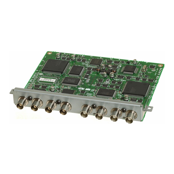
- Page 10 Installation Table of Contents Overview ................. 10 Installation ..............12 Overview The DSBK-1801/1802/1803/1601/1602 are optional boards for the Sony DSR-1800/1800P Digital Videocassette Recorder and DSR-1600/1600P Digital Videocassette Player. They have the following features. DSBK-1801 DSBK-1803 DSBK-1802 DSBK-1601 DSBK-1602 DSBK-1801 SDI (Serial Digital Interface)/AES/EBU Input/Output...
- Page 11 When installed in the DSR-1600/1600P, allows SDTI (QSDI)- format video, audio, and timecode signals to be output at normal speed to the Sony EditStation. This board also allows compressed signals to be output from the DSR-1600/1600P to other DVCAM VCRs.
- Page 12 • Before starting the installation operation, be sure to switch off the power of the videocassette recorder or player. Proceed as follows to install an optional DSBK-1801/1802/ 1803/1601/1602 board in the DSR-1800/1800P/1600/1600P (called “the unit” below). Remove the top panel of the unit.
- Page 13 The blank panel to remove depends on the optional board you are installing. To install the DSBK-1801 or DSBK-1601, you need to remove two blank panels (see the figure below). Remove to install the DSBK-1801/1601. Rear panel of unit Remove to install the DSBK-1802/1602.
- Page 14 Rear panel of unit Attachment screw holes for DSBK-1802/1602 (3 holes) Attachment screw holes for Attachment screw holes for DSBK-1801/1601 (4 holes) DSBK-1803 (3 holes) Example: Installing the DSBK-1803 DSBK-1803 Rear panel of unit Attachment screw holes on the board 02GB06BOD-UC.p65...
- Page 15 Press down on the center of the board to connect the connector of the board to the connector of the unit, and then fasten the board in place with the supplied screws. Example: Installing the DSBK-1803 Replace the top panel of the unit. 02GB06BOD-UC.p65 6/6/01, 3:06 PM DSBK-1801/1802/1803/1601/1602 3-204-692-02(1)
- Page 16 Ce produit est prévu pour être utilisé dans les environnements électromagnétiques suivants: E1 (résidentiel), E2 (commercial et industrie légère), E3 (urbain extérieur) et E4 (environnement EMC contrôlé ex. studio de télévision). Sommaire Aperçu ................17 Installation ..............19 03FR07TOC-UC.p65 6/6/01, 3:06 PM DSBK-1801/1802/1803/1601/1602 3-204-692-02(1)
- Page 17 Aperçu Les cartes DSBK-1801/1802/1803/1601/1602 sont des cartes optionnelles destinées aux magnétoscopes enregistreurs numériques DSR-1800/1800P et aux magnétoscopes lecteurs numériques DSR-1600/1600P Sony. Voici leurs caractéristiques. DSBK-1801 DSBK-1803 DSBK-1802 DSBK-1601 DSBK-1602 Carte d’entrée/sortie SDI (interface numérique série)/AES/EBU DSBK-1801 Installée dans un DSR-1800/1800P, cette carte permet l’entrée et sortie de signaux vidéo et audio numériques en format D1, et...
- Page 18 A l’installation dans un DSR-1800/1800P/1600/1600P, elle permet la connexion du magnétoscope enregistreur ou lecteur à des connecteurs DV compatibles i.LINK d’autres appareils Sony pour permettre le montage et la copie de signaux numériques. Carte de sortie SDI/AES/EBU DSBK-1601 Installée dans un DSR-1600/1600P, elle permet la sortie de signaux vidéo et audio numériques en format D1, et celle de...
- Page 19 • Avant de commencer l’installation, n’oubliez pas de mettre le magnétoscope enregistreur ou lecteur hors tension. Procédez comme suit pour installer une carte DSBK-1801/ 1802/1803/1601/1602 dans un DSR-1800/1800P/1600/1600P (appelé ci-dessous “l’appareil”). Retirez le panneau supérieur de l’appareil.
- Page 20 La plaque de suppression à retirer dépend de la carte en option à installer. Pour installer la DSBK-1801 ou DSBK-1601, retirez deux plaques de suppression (voir la figure ci-dessous). Panneau arrière de Retirez pour installer la DSBK-1801/1601.
- Page 21 Panneau arrière de l’appareil Trous à vis de fixation pour DSBK-1802/1602 (3 trous) Trous à vis de fixation pour Trous à vis de fixation pour DSBK-1801/1601 (4 trous) DSBK-1803 (3 trous) Exemple: Installation de la DSBK-1803 DSBK-1803 Panneau arrière de l’appareil Trous à...
- Page 22 Appuyez sur le centre de la carte pour raccorder le connecteur de la carte au connecteur de l’appareil, puis fixez la carte en place avec les vis fournies. Exemple: Installation de la DSBK-1803 Remettez le panneau supérieur de l’appareil en place. 03FR08BOD-UC.p65 6/6/01, 3:06 PM DSBK-1801/1802/1803/1601/1602 3-204-692-02(1)
- Page 23 Dieses Produkt ist für den Einsatz unter folgenden elektromagnetischen Bedingungen ausgelegt: E1 (Wohnbereich), E2 (kommerzieller und in beschränktem Maße industrieller Bereich), E3 (Stadtbereich im Freien) und E4 (kontrollierter EMV-Bereich, z.B. Fernsehstudio). Inhaltsverzeichnis Übersicht ................ 24 Installation ..............26 04DE09TOC-UC.p65 6/6/01, 3:06 PM DSBK-1801/1802/1803/1601/1602 3-204-692-02(1)
- Page 24 Installation Übersicht DSBK-1801/1802/1803/1601/1602 sind optionale Karten für den Digital Videocassette Recorder DSR-1800/1800P und den Digital Videocassette Player DSR-1600/1600P von Sony. Sie haben die nachstehend aufgeführten Merkmale. DSBK-1801 DSBK-1803 DSBK-1802 DSBK-1601 DSBK-1602 DSBK-1801 SDI (Serial Digital Interface)/AES/EBU Ein-/ Ausgangskarte Bei Installation in den DSR-1800/1800P ist die Ein- und Ausgabe von digitalen Video- und Audiosignalen im Format D1 möglich sowie auch die Ein- und Ausgabe von digitalen...
- Page 25 Bei Einbau in einen DSR-1800/1800P/1600/1600P erlaubt diese Karte den Anschluß des Videorecorders oder Players an i.LINK-kompatible DV-Buchsen von anderen Geräten von Sony zum Schneiden und Überspielen von digitalen Signalen. DSBK-1601 SDI/AES/EBU-Ausgangskarte Bei Installation in den DSR-1600/1600P ist die Ausgabe von digitalen Video- und Audiosignalen im D1-Format möglich...
- Page 26 • Stellen Sie vor der Installation sicher, daß die Stromversorgung des Videorecorders oder Players abgeschaltet ist. Gehen Sie gemäß dem nachstehend beschriebenen Verfahren zum Einbau einer optionalen Karte DSBK-1801/1802/1803/ 1601/1602 in den DSR-1800/1800P/1600/1600P vor (im folgenden als “Gerät” bezeichnet). Entfernen Sie die obere Abdeckung des Geräts.
- Page 27 Entfernen Sie die Blindplatte von der Rückseite des Geräts. Die abzunehmende Blindplatte richtet sich nach der einzubauenden optionalen Karte. Zur Installation der DSBK-1801 oder DSBK-1601 müssen Sie zwei Blindplatten entfernen (siehe die folgenden Abbildung). Zur Installation der DSBK-1801/1601 Rückseite des entfernen.
- Page 28 Befestigungsschrauben des Geräts. Rückseite des Geräts Bohrungen der Befestigungsschrauben für DSBK-1802/1602 (3 Stellen) Bohrungen der Befestigungsschrauben Bohrungen der Befestigungsschrauben für für DSBK-1801/1601 DSBK-1803 (3 Stellen) (4 Stellen) Beispiele: Installation der DSBK-1803 DSBK-1803 Rückseite des Geräts Schraubenbohrungen auf der Karte 04DE10BOD-UC.p65...
- Page 29 Drücken Sie auf die Mitte der Karte, damit sich die Steckverbinder von Karte und Gerät miteinander verbinden, und sichern Sie dann die Karte in ihrer Position mit den mitgelieferten Schrauben. Beispiele: Installation der DSBK-1803 Bringen Sie die obere Abdeckung wieder an. 04DE10BOD-UC.p65 6/6/01, 3:06 PM DSBK-1801/1802/1803/1601/1602 3-204-692-02(1)
- Page 30 Questo prodotto è destinato all’uso nei seguenti ambienti elettromagnetici: E1 (residenziali), E2 (commerciali e industriali leggeri), E3 (esterni urbani) e E4 (ambienti EMC controllati, ad esempio studi televisivi). Indice Descrizione ..............31 Installazione ..............33 05IT11TOC-UC.p65 6/6/01, 3:06 PM DSBK-1801/1802/1803/1601/1602 3-204-692-02(1)
- Page 31 DSBK-1803 DSBK-1802 DSBK-1601 DSBK-1602 DSBK-1801 Scheda di ingresso/uscita SDI (Serial Digital Interface)/AES/EBU Quando è installata sul DSR-1800/1800P, permette l’ingresso e l’uscita di segnali digitali video e audio nel formato D1 e permette inoltre l’ingresso e l’uscita di segnali digitali audio nel formato AES/EBU.
- Page 32 DSBK-1803 Scheda di ingresso/uscita i.LINK Quando è installata sul DSR-1800/1800P/1600/1600P, permette di collegare il videoregistratore o videolettore a connettori DV compatibili i.LINK di altri dispositivi Sony per eseguire il montaggio e la duplicazione di segnali digitali. DSBK-1601 Scheda di uscita SDI/AES/EBU Quando è...
- Page 33 • Prima di iniziare l’operazione di installazione, assicurarsi di spegnere il videoregistratore o videolettore. Procedere come segue per installare una scheda opzionale DSBK-1801/1802/1803/1601/1602 sul DSR-1800/1800P/1600/ 1600P (chiamato “apparecchio” qui sotto). Rimuovere il pannello superiore dell’apparecchio. (Continua) 05IT12BOD-UC.p65...
- Page 34 Rimuovere il pannello cieco appropriato dal pannello posteriore dell’apparecchio. Il pannello cieco da rimuovere dipende dalla scheda opzionale che si vuole installare. Per installare la DSBK-1801 o DSBK-1601, è necessario rimuovere due pannelli ciechi (vedere la figura sotto). Rimuovere per installare la Pannello posteriore DSBK-1801/1601.
- Page 35 Pannello posteriore dell’apparecchio Fori per vite di fissaggio per DSBK-1802/1602 (3 fori) Fori per vite di fissaggio per Fori per vite di fissaggio per DSBK-1801/1601 (4 fori) DSBK-1803 (3 fori) Esempio: Installazione della DSBK-1803 DSBK-1803 Pannello posteriore dell’apparecchio Fori per vite di fissaggio sulla scheda (Continua) 05IT12BOD-UC.p65...
- Page 36 Premere in basso sul centro della scheda per collegare il connettore della scheda al connettore dell’apparecchio e quindi fissare la scheda in posizione con le viti in dotazione. Esempio: Installazione della DSBK-1803 Rimettere il pannello superiore dell’apparecchio. Sony Corporation Printed in China 05IT12BOD-UC.p65 6/6/01, 3:06 PM DSBK-1801/1802/1803/1601/1602 3-204-692-02(1)
Need help?
Do you have a question about the DSBK-1801 and is the answer not in the manual?
Questions and answers