Table of Contents
Advertisement
Advertisement
Table of Contents

Subscribe to Our Youtube Channel
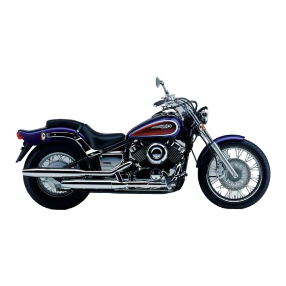
Summary of Contents for Yamaha XVS650 ’97
- Page 3 Supplementary Service Manual together with the following manual. XVS650 ’97 SERVICE MANUAL: 4VR-AE1 XVS650 ’97 SUPPLEMENTARY SERVICE MANUAL © 1997 by Yamaha Motor Co., Ltd. First Edition, January 1997 All rights reserved. Any reproduction or unauthorized use without the written permission of Yamaha Motor Co., Ltd.
-
Page 4: Important Information
EB001000 NOTICE This manual was produced by the Yamaha Motor Company primarily for use by Yamaha dealers and their qualified mechanics. It is not possible to include all the knowledge of a mechanic in one manual, so it is assumed that anyone who uses this book to perform main- tenance and repairs on Yamaha motorcycles has a basic understanding of the mechanical ideas and the procedures of motorcycle repair. -
Page 5: How To Use This Manual
EB002000 HOW TO USE THIS MANUAL MANUAL ORGANIZATION This manual consists of chapters for the main categories of subjects. (See “Illustrated sym- bols”) 1st title 1: This is the title of the chapter with its symbol in the upper right corner of each page. - Page 6 EB003000 ILLUSTRATED SYMBOLS Illustrated symbols 1 to 9 are printed on SPEC the top right of each page and indicate the INFO subject of each chapter. 1 General information 2 Specifications INSP 3 Periodic inspections and adjustments 4 Engine 5 Cooling system 6 Carburetion 7 Chassis 8 Electrical...
-
Page 7: Table Of Contents
CONTENTS GENERAL INFORMATION ................1 MOTORCYCLE IDENTIFICATION............1 VEHICLE IDENTIFICATION NUMBER ..........1 MODEL LABEL..................1 SPECIFICATIONS ..................... 2 GENERAL SPECIFICATIONS ..............2 MAINTENANCE SPECIFICATIONS ............3 ENGINE ....................3 ELECTRICAL..................3 CHASSIS ....................4 CABLE ROUTING ..................5 CARBURETION ....................7 AIR INDUCTION SYSTEM (AIS) <For CH, A>... -
Page 9: General Information
MOTORCYCLE IDENTIFICATION INFO EB100000 GENERAL INFORMATION MOTORCYCLE IDENTIFICATION VEHICLE IDENTIFICATION NUMBER EB100010 The vehicle identification number 1 is stamped into the right side of the steering head. MODEL LABEL The model label 1 is affixed to the frame. This information will be needed to order spare parts. -
Page 10: Specifications
SPEC GENERAL SPECIFICATIONS SPECIFICATIONS GENERAL SPECIFICATIONS Model Standard Model XVS650 Model code: 4XP1/2 (CH, A) 4XR1/2 (D, F, NL, GB, E) Basic weight (with oil and a full fuel tank): 227 kg (D, F, NL, GB, E) 229 kg (CH, A) –... -
Page 11: Maintenance Specifications
SPEC MAINTENANCE SPECIFICATIONS MAINTENANCE SPECIFICATIONS ENGINE Item Standard Limit Carburetor: I. D. mark 4XR 00 (D, F, NL, GB, E) 4XP 00 (CH, A) ---- ← Main jet (M.J) ---- ← Main air jet (M.A.J) ---- Jet needle (J.N) 4CZ11-3 4CT2-2 ---- Needle jet... -
Page 12: Chassis
SPEC MAINTENANCE SPECIFICATIONS Item Standard Limit 30 A × 1 Reserve ---- 15 A × 1 Reserve ---- 10 A × 1 Reserve ---- CHASSIS Tightening torques Tightening torque Part to be tightened Thread size Remarks m·kg Brake pedal – 4 –... -
Page 13: Cable Routing
SPEC CABLE ROUTING CABLE ROUTING Å Position the spark plug lead in front of the fuel tank. 1 Thermo switch ı Pass the fuel tank breather hose through the hose 2 Spark plug lead 3 Fuel tank breather hose guide. Ç... - Page 14 SPEC CABLE ROUTING Å To the rollover valve 1 Fuel tank breather hose ı To the engine 2 Carburetor Ç From the fuel cock 3 Fuel hose Î Position the hose clip tabs downward. 4 Fuel filter ‰ From the fuel tank 5 Spark plug lead Ï...
-
Page 15: Carburetion
CARB AIR INDUCTION SYSTEM (AIS) <For CH, A> CARBURETION EB601000 AIR INDUCTION SYSTEM (AIS) <For CH, A> AIR INJECTION This system burns the unburned exhaust gases by injecting fresh air (secondary air) at the exhaust port. This is to reduce the output of the hydrocarbons. -
Page 16: Air Induction System Inspection
CARB AIR INDUCTION SYSTEM (AIS) <For CH, A> ı ı Ç Ç ı Î Ç Å ı Ç 1 Reed valve AIR INDUCTION SYSTEM INSPECTION 2 Air filter 1.Inspect: 3 Air cut-off valve Hose connections 4 Carburetor joint (front cylinder) Poor connections →...


Need help?
Do you have a question about the XVS650 ’97 and is the answer not in the manual?
Questions and answers