Riello RL 190 Installation, Use And Maintenance Instructions
Two-stage operation
Hide thumbs
Also See for RL 190:
- Installation, use and maintenance instructions (88 pages) ,
- Two-stage operation (60 pages) ,
- Installation, use and maintenance instructions (80 pages)

Subscribe to Our Youtube Channel
Related Manuals for Riello RL 190


Summary of Contents for Riello RL 190
- Page 1 Installation, use and maintenance instructions Gas oil burner Two-stage operation CODE MODEL TYPE 20032719 RL 190 673 T1 20033310 (2) - 04/2011...
-
Page 3: Table Of Contents
Contents Declaration....................................3 Information and general warnings............................4 Information about the instruction manual ........................4 2.1.1 Introduction.................................. 4 2.1.2 General dangers................................4 2.1.3 Danger: live components............................. 4 Guarantee and responsibility............................5 Guidance for the use of bio fuel blends up to 10%...................... 5 2.3.1 Information and general instructions ........................... - Page 4 Contents Burner calibration ...............................21 7.3.1 Combustion head setting ............................21 7.3.2 1st and 2nd stage nozzles ............................21 7.3.3 Pump pressure .................................22 7.3.4 1st stage fan air gate valve .............................22 7.3.5 2st stage fan air gate valve .............................22 Burner operation ................................23 7.4.1 Burner starting ................................23 7.4.2 Steady state operation ...............................24...
-
Page 5: Declaration
The quality is guaranteed by a quality and management system certified in accordance with UNI EN ISO 9001. Manufacturer's Declaration RIELLO S.p.A. declares that the following products comply with the NOx emission limits specified by German standard “1. BImSchV release 26.01.2010”. -
Page 6: Information And General Warnings
Information and general warnings Information and general warnings Information about the instruction manual 2.1.1 Introduction 2.1.3 Danger: live components The instruction manual supplied with the burner: This symbol indicates operations which, if not car- is an integral and essential part of the product and must not ried out correctly, lead to electric shocks with le- be separated from it;... -
Page 7: Guarantee And Responsibility
All components within the hydraulic circuit suitable for manual, operating negligence, incorrect installa- bio fuel use and supplied by Riello will be identified as Bio com- tion and carrying out of non authorised modifica- patible. No warranty is given in relation to the use of components... -
Page 8: Information And General Instructions
If this is not completed then due to the hydro- In no event shall Riello (and its subsidiaries) be liable for any in- scopic nature of Bio fuel, it will effectively clean the tank,... -
Page 9: Safety And Prevention
Safety and prevention Safety and prevention Introduction The burners have been designed and built in compliance with the type and pressure of the fuel, the voltage and frequency of the current regulations and directives, applying the known technical electrical power supply, the minimum and maximum deliveries for rules of safety and envisaging all the potential danger situations. -
Page 10: Technical Description Of The Burner
3 / 220-380 / 60 3 / 220V / 60Hz - 3N / 380V / 60Hz Auxiliary voltage : 230/50/60 230V / 50-60Hz 110/50/60 110V / 50-60Hz 3/400/50 230/50-60 BASIC DESIGNATION EXTENDED DESIGNATION Models available Designation Electrical supply Code RL 190 3/400/50 20032719 20033310... -
Page 11: Technical Data
Technical description of the burner Technical data Model RL 190 Type 673 T1 Output stage 1423 - 2443 Delivery Mcal/h 1224 - 2100 kg/h 120 - 206 stage 759 - 1423 Mcal/h 653 - 1224 kg/h 64 - 120 Fuel... -
Page 12: Packaging - Weight
Tab. B. • The weight of the burner complete with packaging is indicat- ed in Tab. B. Fig. 1 RL 190 1270 Tab. B Overall dimensions The maximum dimensions of the burner are given in Fig. 2. The maximum dimension of the burner, without casing, when Bear in mind that inspection of the combustion head requires the open is give by measurement I. -
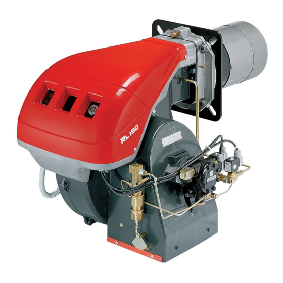
Page 13: Burner Description
Bio blend, it will be essential to use flexible oil 2 - Nipples for flexible hoses lines suitable for bio fuel use. Please contact Riello for further information. WARNING 1 - Thermal insulation screen 4 - Extensions 13) for slide bars 12)(Fig. 5) -
Page 14: Installation
In the event of doubt, do not use the burner; contact the supplier. CAUTION The packaging elements (wooden cage or card- RIELLO S.p.A. board box, nails, clips, plastic bags, etc.) must not 0036 I−37045 Legnago (VR) -
Page 15: Installer/Servicer Notes For The Use Of Gas Oil With Bio Blends Up To 10
The burner hydraulic components and flexible oil lines must burner technical manual). be suitable for bio fuel use (check with Riello if in doubt). If a Bio blend is in use the installer must seek information Riello have carefully chosen the specification of the bio... -
Page 16: Blast Tube Length
12 bar 14 bar In order to guarantee that emissions do not vary, recommended 5.00 19.2 21.2 23.1 251.4 and/or alternative nozzles specified by Riello in the Instruction 5.50 21.1 23.3 25.4 276.3 and warning booklet should be used. 6.00 23.1... -
Page 17: Nozzle Assembly
Installation Use nozzles with a 60° spray angle at the recom- mended pressure of 12 bar. WARNING As a rule the two nozzles have equal deliveries but the 1 stage nozzle may have a delivery less than 50% of the total delivery when a reduction of the counter-pressure peak is desired at the moment of starting (the burner allows good combustion rates also with a 40 - 100 % ratio between the 1... -
Page 18: Gas Oil Supply
DANGER You are advised to use additional filters on the fuel supply line. Riello recommends a good quality fuel filter at the tank (Fig. 14 - Fig. 15) and a secondary filter CAUTION (100 for gas oil and 15... -
Page 19: 5.10.3 Single-Pipe Circuit
Installation 5.10.3 Single-pipe circuit In order to obtain single-pipe working it is necessary to unscrew the return hose, remove the by-pass screw 6)(Fig. 25) and then screw the plug 7)(Fig. 25). The distance “P” must not exceed 10 meters in order to avoid subjecting the pump's seal to excessive strain;... -
Page 20: Pump
Bio blend, it will be essential to use flexible oil Before starting the burner, make sure that the lines suitable for bio fuel use. tank return line is not clogged. Please contact Riello for further information. WARNING Obstructions in the line could cause the seal- WARNING ing organ located on the pump shaft to break. -
Page 21: Electrical System
Electrical connections Electrical wiring must be made in accordance with the regulations currently in force in the country of destination and by qualified personnel. Riello S.p.A. declines all liability for modifications WARNING or connections other than those shown on these diagrams. -
Page 22: Calibration Of Thermal Relay
Electrical system Calibration of thermal relay This is required to avoid motor burn-out in the event of a signifi- cant increase in power absorption caused by a missing phase. • If the motor is star-powered, 400V, the cursor should be po- sitioned on "MIN". -
Page 23: Start-Up, Calibration And Operation Of The Burner
Start-up, calibration and operation of the burner Start-up, calibration and operation of the burner Notes on safety for the first start-up The first start-up of the burner must be carried out Check the correct working of the adjustment, com- by qualified personnel, as indicated in this manual mand and safety devices. -
Page 24: Pump Pressure
Start-up, calibration and operation of the burner 7.3.3 Pump pressure 12 bar: this is the pressure calibrated in the factory which is usually sufficient for most purposes. Sometimes, this pressure must be adjusted to: 10 bar: in order to reduce fuel delivery. This adjustment is pos- sible only if the surrounding temperature remains above 0°C. -
Page 25: Burner Operation
Start-up, calibration and operation of the burner Burner operation 7.4.1 Burner starting Starting phases with progressive time intervals shown in sec- onds: control device TL closes. After about 3s: The control box starting cycle begins. 0 s: 2 s: The fan motor starts. 3 s: The ignition transformer is connected. -
Page 26: Steady State Operation
Start-up, calibration and operation of the burner 7.4.2 Steady state operation Systems not equipped with control device TR (jumper wire installed) System equipped with one control device TR The burner is fired as described in the case above. If the temper- Once the starting cycle has come to an end, the command of the ature or pressure increase until control device TL opens, the stage solenoid valve passes on to the control device TR that... -
Page 27: Maintenance
Maintenance Maintenance Notes on safety for the maintenance The periodic maintenance is essential for the good operation, Before carrying out any maintenance, cleaning or checking oper- safety, yield and duration of the burner. ations: It allows you to reduce consumption and polluting emissions and to keep the product in a reliable state over time. -
Page 28: Opening The Burner
Maintenance Pump Nozzles The delivery pressure must be stable. The depression must be Do not clean the nozzle openings; do not even open them. less than 0.4 bar. Unusual noise must not be evident during pump The nozzle filters however may be cleaned or replaced as re- operation. -
Page 29: Burner Start-Up Cycle Diagnostics
Maintenance Burner start-up cycle diagnostics During start-up, indication is according to the Tab. I: Sequences Colour code Pre-purging Ignition phase Operation, flame ok Operating with weak flame signal Electrical supply lower than ~ 170V Lock-out Extraneous light Key: Yellow Green Tab. -
Page 30: Faults - Possible Causes - Solutions
Faults - Possible causes - Solutions Faults - Possible causes - Solutions Find a list of faults, causes and possible solutions for a set of failures that may occur and result in irregular burner operation or no functioning at all. If a burner malfunction is detected, first of all: •... - Page 31 Faults - Possible causes - Solutions SIGNAL FAULT POSSIBLE CAUSE SOLUTION The burner does Control device TR does not close Adjust or replace not pass to 2nd Defective control box Replace stage 2nd stage solenoid valve coil defective Replace Piston jammed in valve unit Replace entire unit Fuel passes to 2nd Low pump pressure...
-
Page 32: A Appendix - Accessories (Optional)
3); Degassing units are provided in two versions: fasten Status to the bracket using the screws 4) supplied with the kit. Burner Code RL 190 (without filter) 20034277 RL 190 (with filter) 20034281 Degassing unit characteristics Burner output 80 kg/h max Fuel pressure 0.7 bar max... - Page 33 Appendix - Accessories (optional) 1st stage operating hours Total hours - 2nd stage operating hours Number of firings Press button "count". Resetting operating hours and number of firings Press the three “reset” buttons simultaneously. Non-volatile memory The operating hours and the number of firings will remain in the memory even in the case of electrical power failures.
-
Page 34: B Appendix - Electrical Panel Layout
Appendix - Electrical panel layout Appendix - Electrical panel layout ELECTRICAL EQUIPMENT FACTORY-SET D3236 Fig. 3 The burner leave the factory preset for 400V power supply. If 230V power supply is used, change the motor connection from star to delta and change the setting of the thermal cut-out as well. - Page 35 Appendix - Electrical panel layout Key to layout Motor contactor Photoresistor Switch: burner off - on Switch: 1 stage operation Terminal strip Fan motor RMO... Control box Thermal cut-out Ignition transformer Burner ground (earth) connection 1st stage solenoid valve stage solenoid valve Safety solenoid valve Connector for STATUS 4 pole socket...
Need help?
Do you have a question about the RL 190 and is the answer not in the manual?
Questions and answers