
Subscribe to Our Youtube Channel
Related Manuals for dixell iPRO


Summary of Contents for dixell iPRO
- Page 1 PROGRAMMABLE CONTROLLER OPERATION MANUAL iPRO.GENIUS Vers. 1.0 ________________________________________________________________________________________________________ 1592025400 – Vers. 1.0...
- Page 2 ________________________________________________________________________________________________________ 1592025400 – Vers. 1.0...
- Page 3 4.13 Expansion module (specifications and connections) 4.14 Other connections HOW TO START Ethernet 10/100 connection Direct connection (between iPRO and PC with a cable) Intranet/Ethernet connection (Local Area Network) Port forwarding Modem connection ISAGRAF INSTALLATION AND SET-UP Requirements How to install the ISaGRAF software...
- Page 4 8. PROGRAMMING LANGUAGES ST language – General concepts FBD language – General concepts 8.2.1 FBD example – ON/OFF regulator FB function block 8.3.1 Introduction of Function Block FB 8.3.2 How to create the FB 8.3.3 How to use the FB inside the programs 8.3.4 Exportation and Importation of FB Configuration files...
- Page 5 14. CONNECTIVITY 14.1 Ethernet 10/100 and Serial bus 14.2 How to configure the bus and variables 14.2.1 Define the BUS (GENLINE board) 14.2.2 Define the I/O (GENAI, GENAO, GENDI, GENDO boards) 14.2.3 Define the new variable(s) in the dictionary 14.2.4 Link between variables and boards 15.
- Page 6 MAINTENANCE (SERVICING) INSTRUCTIONS IN THE LITERATURE ACCOMPANYING THE APPLIANCE. WARNING: Dixell Spa can accept no responsibility for any possible damage due the usage of not supported modems. Dixell Spa. reserves itself the right to modify this manual without notice. The last version available can be downloaded from the website.
- Page 7 3. INTRODUCTION 3.1 Main Features iPRO family, dedicated whether for HVAC units (iPRO Chill and Domo) or for general purposes and refrigeration (iPRO Genius), is characterized by the most advanced technology in connectivity and processing speed. It is based on a powerful platform that includes one hardware configuration that is able to expand the actual solution in the market, and a software that, thanks to the ISaGRAF®...
- Page 8 I/O expansion modules. • Two master and slave RS485 serial output. • ModBUS-RTU standard communication protocol that allows connection to Dixell digital controllers, to XWEB supervising and controlling systems or to applications developed by third Party Systems.
- Page 9 3.5 ISaGRAF In order to create programs that will be uploaded into the iPro series Dixell has selected ISaGRAF®; a software environment that enables you to create local or distributed control systems. ISaGRAF® offers a combination of a highly portable, robust management engine (Virtual Machine) and an intuitive application development environment (Workbench).
- Page 10 • LD: Ladder Diagram 3.7 Development tools IPRO-TOOL is a complete tool, provided by Dixell, that allows the final user to work independently to create programs for iPRO controllers, taking advantage of all the programmable series potential. The package includes manuals and the WIZMATE software, a useful instrument that allows a simple iPRO controllers programming mode.
- Page 11 The user can choose between two options: 3.8 Upgrade programs from previous version of ISaGRAF (3.x) For iPRO is possible to manage programs that have been developed with ISaGRAF 3.x version; it is not possible the opposite. If the program contains ISaGRAF standard function block, they can be converted automatically.
- Page 12 If necessary, inside the CD-ROM you will find the Java Virtual Machine program distributed by Sun® Microsystems. Dixell S.p.a. is not responsible for any kind of damage occurring after the loading of the Java Virtual Machine program into the user’s PC.
- Page 13 4. BASIC Input/Output CONFIGURATION Configurable means that every inputs or output can be configured different each other. ________________________________________________________________________________________________________ 1592025400 – Vers. 1.0 - 13...
- Page 14 4.1 Power Supply 4.2 Analog Inputs (Probes PTC-NTC) ________________________________________________________________________________________________________ 1592025400 – Vers. 1.0 - 14...
- Page 15 4.3 Analog Inputs (Pressure transducers 4÷20mA, probes 0÷20mA) 4.4 Analog Inputs (Pressure transducers 0÷1V, Ratiometric 0÷5V - 0÷10V) 4.5 Analog Inputs (Probes 0÷1V - 0÷10V) ________________________________________________________________________________________________________ 1592025400 – Vers. 1.0 - 15...
- Page 16 4.6 Analog Outputs (0÷10V - 4÷20mA signal for condenser controls) 4.7 Analog Outputs (PWM signal for fan speed module) ________________________________________________________________________________________________________ 1592025400 – Vers. 1.0 - 16...
- Page 17 4.8 Analog Outputs (proportional signal 0÷10V, 4÷20mA for actuators/ servo-motors) 4.9 Analog Outputs (configured to control remote relay) ________________________________________________________________________________________________________ 1592025400 – Vers. 1.0 - 17...
- Page 18 4.10 Digital Inputs 4.11 Digital Outputs ________________________________________________________________________________________________________ 1592025400 – Vers. 1.0 - 18...
- Page 19 4.12 Visograph connection IT IS VERY IMPORTANT TO RESPECT THE POLARITY OF CONNECTIONS TO AVOID THE DAMAGING OF THE VISOGRAPH. ________________________________________________________________________________________________________ 1592025400 – Vers. 1.0 - 19...
- Page 20 4.13 Expansion Module (specifications and connections) Power supply: 24V Vac/dc Analog Inputs: 7 configurable 0÷1V, 0÷5V, 0÷10V, 0÷20mA, 4÷20mA, NTC, PTC, DI Analog Outputs: 3 configurable 0÷10V ( or DO for relay) Digital Inputs: 3 (free contacts) Digital Output: 6 relay 5A 250V Can bitrate = 100Kbit/s Connection: 1 CANBus (set-up this value...
- Page 21 4.14 Other connections For all the other connections, please refer to the section No. 14. ________________________________________________________________________________________________________ 1592025400 – Vers. 1.0 - 21...
- Page 22 • To connect more iPRO; different applications on different iPRO to exchanges variables. • To send mail and sms; you can program your iPRO so that it can sends mail/sms on time or on demand. • To visit your own website; you can program iPRO with your own web site. With a standard browser, a user can read/write variables.
- Page 23 • Disconnect your computer from the data network of your company and connect the PC with the iPRO through the Crossover cable. • The personal computer has to be set in the same network of the iPRO. o In the windows environment click with the mouse on “start” button o Choose “Control Panel”...
- Page 24 Launch the browser in your computer and write the following web site address: http://192.168.0.250/panel (if your IP is different, write the correct one): If necessary is possible to change the IP address; click the Configuration button and in the IP box write the new address (for example if your IP address is: 192.168.0.233). Click “OK”...
- Page 25 If everything is ok, the message will be: Now it is necessary to restart the iPRO. To test the connection follows the procedure in the chapter 5.3. ________________________________________________________________________________________________________ 1592025400 – Vers. 1.0 - 25...
- Page 26 The Intranet or Ethernet connection should be initially managed by the net administrator that will assign one free IP address to reach the iPRO. This number is an example of what you should expect with the default IP of the iPRO: 192.168.0.250.
- Page 27 If the connection is OK, in this window you will see the following information: 5.4 Port forwarding Port forwarding allows remote computers (e.g. public machines on the Internet) to connect to a specific computer within a private LAN. The ports that have to be opened are: •...
- Page 28 6. ISAGRAF INSTALLATION AND SET-UP 6.1 Requirements To develop the software with ISaGRAF are necessary: • Software (it is possible to install the program from the CD or download it from the ISaGRAF Website). • To have the ISaGRAF USB KEY 6.2 How to install the ISaGRAF software Insert the CD in your computer;...
- Page 29 Please install ONLY the programs selected as showed here below: …and then: “Next” These are the programs that you are installing… …and then: “Next” ________________________________________________________________________________________________________ 1592025400 – Vers. 1.0 - 29...
- Page 30 …select: “Install” Choose the languages… …select: “Next” At the end of the installation, please restart the computer …select: “Finish” ________________________________________________________________________________________________________ 1592025400 – Vers. 1.0 - 30...
- Page 31 Downloads. Then choose the ISaGRAF version to download (before to do this, check the Dixell website to verify the latest revision approved by Dixell). The procedure to install and set-up of ISaGRAF software is the same as above.
- Page 32 Second, in the disk “C:\” , copy the folder “Dixell” as showed here below. Inside this folder, there is the DIXELL GFL (general function library). You can find this folder inside the Dixell website in the “ISaGRAF Function Blocks” section. ________________________________________________________________________________________________________ 1592025400 –...
- Page 33 6.5 Start with the new Project Launch the ISaGRAF program and select: File - Open Project/Library The file to open is inside the project that we have saved in: • C:\Programmi\ICS Triplex ISaGRAF\Projects\ISaGRAF 5.1\Prj This is the folder where your project has been saved Double click on Prj ________________________________________________________________________________________________________...
- Page 34 When you have opened your project, it is important to import the “tdb” file. This file has been generated by Dixell to describe the property of iPRO to the ISaGRAF workbench; this file include all the latest information about the improvement of the standard application of iPRO.
- Page 35 Then save and compile again; The new messages should be: All these file are available in the Dixell web site (www.dixell.com) inside the support area. Pay attention because if you have already developed your project with an old version of the tdb file is not necessary to import the new one in your project.
- Page 36 If the vertical bar is not visible, move the “Config” window until the vertical bar will appear. Write inside the box the IP address of your iPRO, then OK. Now the set-up of ISaGRAF is completed and you can start with your application.
- Page 37 Resource: it is your project; inside there are the elements of your project. The elements of your project are: Programs: it is the software that you develop to execute your application. In this picture, for every PLC Cycle, iPRO executes the programs: Read_Inputs Regulator_status_of_controller Regulator _Fans ……...
- Page 38 To check the Cycle Timing choose: Edit Properties Settings During the Debug is possible to verify if the PCT is correct. Choose: Debug Diagnosis, and in the Timing tab all these information are available. ________________________________________________________________________________________________________ 1592025400 – Vers. 1.0 - 38...
- Page 39 Besides you can save them in the library and also protect them with a password. These FB can be developed by ISaGRAF, Dixell and from third party. Variables: they are values that can change during the execution of the program.
- Page 40 • ADDRESS: where to save the value of the variable In the example here below, it is possible to understand how to define the variables. There are some important information that have to be taken in consideration when: the TYPE of the variable is REAL; use this kind of variable only if strictly necessary (for operation with Log, Exp, Cos,…).
- Page 41 7.2 How to make a regulator ON-OFF The purpose of this example is to introduce how to develop a program with ISaGRAF; this first example will be developed with the ST language. Our target is to create a Regulator ON-OFF for Compressor (Direct Action). The diagram of this regulator is: The meaning of this diagram is: •...
- Page 42 Now the new group has been created and we have called it “Group1”. Double click on Group1: Double click below name to fill in all the fields (Name, Comment, Type, Address…) For each variable we have to define the characteristics: Here we have also define the “Address”;...
- Page 43 Change the window from the Dictionary to the Program Click on Insert Add Program and choose the language that you prefer: This example will be developed in ST language. The new program will be called Regulator_for_compressor. The next step is to write the program (double click on Regulator_for_compressor): ________________________________________________________________________________________________________ 1592025400 –...
- Page 44 Comment Program Comment In the example here above, the variables are not linked with the physical output; these variables are only logical. To link these variables with the physical output we have to write another program. The new program will be: ________________________________________________________________________________________________________ 1592025400 –...
- Page 45 The physical input and output are defined inside the Variable Groups “SysParameters”. The AI are the analog inputs, the DI are the digital inputs, the AO are the analog outputs and the DO are the digital outputs. The ConfAI is the value to configure the probe type; for example if your AI01 is a PTC probe, ConfAI01 = 1.
- Page 46 At this moment, we are able to execute the program in two different ways: SIMULATION Execution without the iPRO; this is the first debug of the program because it is immediate and complete (see page 48 for procedure). DEBUG TARGET The application is running on iPRO.
- Page 47 In this window choose “Select All” and then “Download”. Then “Stop and download”. At the end of the transferring this message will appear in the bottom of ISaGRAF. ________________________________________________________________________________________________________ 1592025400 – Vers. 1.0 - 47...
- Page 48 The red semaphore means that the SIMULATION or DEBUG TARGET are running. To stop the execution is enough to click on semaphore. During the execution of the program we can read, write and lock the variables. If you click this icon the variables will appear;...
- Page 49 Here below you can see what is happened: It is also possible to lock and unlock the variable; for example we can lock the variable of compressor. During the test, to avoid to damage the compressor, we can lock the compressor in off (variable must be FALSE) and then change all the other variables to understand what happen in all the other resource of our application (fan, pump, valve,…).
- Page 50 Once the DEBUG is finished, it is important to UNLOCK all the variables. To do this is enough to click on DEBUG DIAGNOSIS, choose the tab “Locked Variables”, and select “Unlock All” as showed here below. ________________________________________________________________________________________________________ 1592025400 – Vers. 1.0 - 50...
- Page 51 7.3 Debug Step by Step This function is useful to check in your application what happen when the inputs change; you can see in which part of your application the program is stopped because it is waiting some new information or event. To enable this function, click on the Resource bar and , with the right button of the mouse, chose Properties;...
- Page 52 Open your program and with this icon add the breakpoints; place the cursor at the beginning of the line of your program and click the breakpoint icon. The red point means that there is a breakpoint in that line of the program. You can add other breakpoint.
- Page 53 BE AWARE: when the debug test has been completed and you are in the DEBUG TARGET, to enable the Watchdog is necessary to reboot the Target (iPRO). When you will launch the debug, the ISaGRAF workbench will ask you the following information;...
- Page 54 The window with your application will be open; a yellow arrow will show you the position where the debug is arrived (obviously if there are breakpoints). Our Debug is arrived here The commands available for the “Debug Step by Step” are: •...
- Page 55 7.4 The ISaGRAF instruction manual Once you have installed the ISaGRAF environment, it is possible to find the complete documentation of ISaGRAF development tool inside the folder: C:\Programmi\ICS Triplex ISaGRAF\Documentation 5.1\Users Guide\..\workbench.pdf ________________________________________________________________________________________________________ 1592025400 – Vers. 1.0 - 55...
- Page 56 8. PROGRAMMING LANGUAGES 8.1 ST language – General concepts The environment of ST language is composed by: • STATEMENT assignment priority IF, THEN, ELSE, ELSIF, END_IF; binary selection CASE, OF, ELSE, END_CASE; selection WHILE, REPEAT, END_WHILE, END_REPEAT; iterations FOR, TO, BY, DO, END_FOR; indexed iterations RETURN;...
- Page 57 • STRING ASSIGNMENT direct copy CONCATENATION concatenates two strings COMPARISON =, <>, >=, <=, >, < alphabetical order • CONVERSION FUNCTION ANY_TO_BOOL conversion to boolean ANY_TO_DINT conversion to double INT ANY_TO_REAL conversion to real ANY_TO_TIME conversion to timer ANY_TO_STRING conversion to string Example: If we have two variables: SEC (type DINT) and SEC1 (type TIME) the assignation: SEC1 := SEC;...
- Page 58 8.2 FBD language – General concepts ________________________________________________________________________________________________________ 1592025400 – Vers. 1.0 - 58...
- Page 59 8.2.1 FBD example – ON/OFF regulator The purpose of this example is to develop the same example of before but with the FBD language. The steps are the same of example No.1 except for the step when you have to add the program;...
- Page 60 Once the FBD is open, we have to put the elements of our application; the first element is the Hysteresis block. Click the icon and then positioning it in the window. With the tab here below select the block and then press OK. To confirm the operation click the icon The other elements to put are the variables (defined in the Group1).
- Page 61 • Recognize if these programs have similar parts. • Recognize if the FB necessary for your programs already exist Take the FB from ISaGRAF library Take the FB from Dixell Library Take the FB from your personal library Develop a new FB for your application •...
- Page 62 • you can create and save for yourself a personal library • you can use a lot of FB made by ISaGRAF, Dixell or third party • the debug of the whole program is more quickly (save time and money)
- Page 63 8.3.2 How to create the FB Starting from the Example No. 1, we can consider to control the following resources: • Fan motor • Alarm for high temperature • Alarm for low temperature The diagram for each of them is: Inverse Action Direct Action Inverse Action...
- Page 64 We can summarize the four diagrams in 2 diagrams: Now we have all the elements to create a FB that we call ONOFF_Regulator. Add a new Function Block using the ST language: This is our new function block; click on it with the right key of the mouse and choose “Parameters / Local Variables”.
- Page 65 Add the 5 variables: Double click on ONOFF_Regulator to write the program in ST language: This is the Function Block that we have created just now: Remember that you can use this FB when you want and all the times that you need. ________________________________________________________________________________________________________ 1592025400 –...
- Page 66 8.3.3 How to use the FB inside the programs More or less the steps are the same used to write the program for Regulator ON/OFF; the only difference is that we have to add the “INSTANCE” to recall the FB inside the variables group.
- Page 67 The last step is to write the program with ST and FBD languages: It is very important to understand that the list of the inputs is not random; the sequence of the inputs must be like the sequence of the instance. TEMPERATURE FALSE SET+BAND...
- Page 68 To complete the job, SAVE, COMPILE and EXECUTE your project. The same program written with FBD language will be: The considerations regarding the FB are: • The description of regulator is immediate and complete. • Every regulator is based on Function Block “ONOFF_Regulator”. •...
- Page 69 8.3.4 Exportation and Importation of FB Through different ISaGRAF applications is possible to transfer the function blocks. • Exportation Select the function block to export (in this example ONOFF_Regulator). Choose File Export Select the directory to save the file (the extension of the file is .pxf). When the process will be finished, choose close in the following window.
- Page 70 • Importation Choose File Import Exchange File Select Import from file: Choose the file saved before or the file in your library (file extension is pxf): ________________________________________________________________________________________________________ 1592025400 – Vers. 1.0 - 70...
- Page 71 Select the exchange file to import: Select the elements to import: If you want it is possible to change the name of function block Check the result of procedure and exit: Now in your project, in the function block folder you will find the ONOFF_Regulator. ________________________________________________________________________________________________________ 1592025400 –...
- Page 72 “. (dot)” not at the first position of the name. The iPRO can manage up to 5 .bin files; inside the iPRO you can save different .bin files for different users: for example one file for service people, one file for production, etc...
- Page 73 6= NET 7=Net Gateway 9=MODSLAVE_Parameters The files can be transfer to the iPRO using the USB; at the end the iPRO will reboot automatically with the new configuration. (It is not necessary to write all the parameters). 8.4.4 File SPALT The spalt files are files necessary to program the iPRO to send e-mail and sms.
- Page 74 • maileth.spalt this file include the parameters necessary to send mail through internet. An example of configuration is: EMAIL_FROM=ipro EMAIL_TO=mario.rossi@libero.it EMAIL_SUBJECT=”test mail” EMAIL_SMTP_SERVER=smtp.libero.it EMAIL_AUTH=on EMAIL_USER=ipro400@gmail.com EMAIL_PASS=ipro400d EMAIL_TLS=on Compile with correct values each field. • mailmodem.spalt this file include the parameters necessary to send mail through the modem.
- Page 75 An example of configuration is: SMS_NUMBER=+391234567890 Compile with correct values each field. All these files can be transfer to the iPRO through the USB. ________________________________________________________________________________________________________ 1592025400 – Vers. 1.0 - 75...
- Page 76 (ISaGRAF file); besides, you can download the application (isadix file – crypted) with the USB key to the iPRO, if the two password are the same (the password inside the iPRO and the password of the new file).
- Page 77 • If the procedure has been correct the message in the ISaGRAF window will be: If you try do download another application without or with a different password the message showed by ISaGRAF will be: To remove the password the procedure is the same as above but in the configuration properties you have to cancel the password.
- Page 78 All these procedure can be done with the iPRO software tool. • From iPRO to PC To transfer the application from iPRO to the PC it is necessary to know the password of application inside the iPRO; if the application is not protected the default password is Dixell.
- Page 79 (only if the IPRO has the same password) • From PC to iPRO To transfer the application from PC to the iPRO it is necessary to know the password of application inside the iPRO; if the application is not protected the default password is Dixell.
- Page 80 All the isadix files created can be downloaded directly in the iPRO using the USB key. It is enough to put the file isadix inside the folder “app” in the USB. For each iPRO and each “app” folder it is possible to use only one isadix file. ________________________________________________________________________________________________________ 1592025400 –...
- Page 81 9.3 How to protect the function block FB When one or more function blocks have been developed than is possible to protect them with a password. The function blocks are visible in the project but to open or modify them it is necessary the password.
- Page 82 Try to save, close and open again the project. Now the block is protect and the colour is red. The exportation and importation are possible but in any case the block will be protected. Only if you know the password will be possible to remove the protection and open the block. To remove the password, double click on the function block: Write the password and confirm;...
- Page 83 “updater-2008090300”. This is iPRO’s IP folder with inside the files only for the single iPRO. If there are more iPRO is enough to create more folders with different IP; inside the IP folders the structure have to be the same.
- Page 84 Visograph, it is enough to create only the “bin” folder. To download or upload the files the procedure is the following: • Introduce the USB key in the usb port of the Ipro. • When the yellow led will blink, the file has been downloaded or uploaded; now you can remove the USB key.
- Page 85 11.1 How to install VISOPROG software To install VISOPROG software are necessary: • Software CD. • To have the PRODUCT KEY (provided by Dixell) Insert the CD in your PC and launch the program and then follow the instruction as showed here below Choose “Avanti”.
- Page 86 Fill in with these information: - Username - Company name - Product Key Then “Avanti”. Choose “Completa….”, then “Avanti”. ________________________________________________________________________________________________________ 1592025400 – Vers. 1.0 - 86...
- Page 87 Choose “Installa.”. Now the installation is completed: choose “Fine” to close the windows ________________________________________________________________________________________________________ 1592025400 – Vers. 1.0 - 87...
- Page 88 • : in this case you have to send the two codes (Product Key and Installation key ) to Dixell by fax or mail to get the Activation Key. • : in this case you can get the Activation Key automatically (an Internet Connection is required) From this moment you can work with VISOPROG.
- Page 89 Open the project copied just now: And choose the file “Keyboard”: Now we have to sep-up the program with some information: • Language to use.(Environment Language) • Connection between Visoprog and iPRO. (Environment Instrument) • Project options (File Options) ________________________________________________________________________________________________________ 1592025400 –...
- Page 90 11.3.1 Environment Language This set-up defines the language used in your environment. Select: Environment Language and choose your preferred language. Pay attention because if your language is not included in the standard languages, you can add it for yourself. Go inside the folder “Languages” that you can find in your default installation directory.
- Page 91 11.3.2 Environment Connection This set-up defines the connection between your personal computer and the iPRO. Select: Environment Instrument and choose the iPRO device. 11.3.3 Project Options This set-up defines all the options of your project. Select: File Options. In these window there are the...
- Page 92 In this window you can define the fonts of your project; for each project you can choose 4 fonts. In every moment you can change the fonts (click on Edit and choose the new one), but pay attention that in your project the previous font will be updated automatically with the new one.
- Page 93 To create and manage your vocabulary in the best way please follows these suggestions: • Define the multi-languages to use in your project. Click this icon and choose the languages to add. • Define the language to use (this is the language that you will see in VISOPROG during the developing of your project);...
- Page 94 First click on “A” , then “B”, “C”, “D” and “E”; in the left table you will see the following structure: Click Import and then OK to finish the procedure. Now your vocabulary has been imported in your project. In this window is possible to associate the variables between the ISaGRAF and VISOPROG projects;...
- Page 95 • Define the ISaGRAF project to link in VISOGRAPH project. Select the ISaGRAF project where Import and Export the variables: • Import the Variables. Confirm the operation. If you click on Variables you will find the variables defined in the project “Example1”. Now is possible to export the excel file, modify and then import the file again;...
- Page 96 In this window there are the images that is possible to use in your project. With the buttons is possible: Add or update the single image. Delete, save and load the whole list of images. Export the single image to modifies it. The recognized formats for images are .gif, .jpg, .bmp, .ico, .emf and .wmf.
- Page 97 In this window you can define the destination folder for your .bin file. The bin file is the compiled file of your project. This is the file to download in your VISOGRAPH interface. In this option is possible to decide which languages to add in the bin file. ________________________________________________________________________________________________________ 1592025400 –...
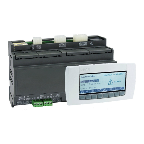
- Page 98 12. VISOGRAPH The VISOGRAPH Human Interface is a graphic lcd display necessary to visualize all the variables defined in the iPRO (remember that only the variables with an address defined in the ISaGRAF project can be visualized). The main characteristics are: •...
- Page 99 The VISOPROG workbench is the environment developed by Dixell to build the human interface in the VISOGRAPH graphic lcd. VISOPROG reads the ISaGRAF project from the iPRO and imports directly variables and function blocks to create automatically the basic interface; then the developer completes the interface adding functionality through the keys.
- Page 100 13.3 The STAGE area The STAGE area is the structure of the project. VISOGRAPH is organized as a sequence of menu called Stages; then, inside each stage, it is possible to create one (SINGLE PAGE) or more pages (MULTIPLE PAGES). If you are inside the stage with multiple pages, it is possible to work in one page for time and the active page is in yellow colour.
- Page 101 In the picture here below an example: Name of the stage This configuration means that after 10 seconds from “Stage1” the display will showed the stage “AI”. attention because the TimeOut period is multiple of 5 seconds. Other information available in this area are: •...
- Page 102 13.4 The STAGE EDITOR area The STAGE EDITOR area is the area where to create the interface of the stage. In this area through the control bar is possible to add labels, variables, Images and switch variables/labels. Inside the control bar there are five options: VarLabel: With this control you can add the variables to visualize the value;...
- Page 103 13.5.1 Object Properties All the controls in VISOPROG have some properties. The properties can be modified thanks to the Object Properties tab. The properties for the control (for example the Dixell image) are: • Left X it is the top left corner value, in the X coordinate, of the control.
- Page 104 In the second window it is possible to put the controls in different layers. to add a new layer to delete a layer For each single layer it is possible to set the visibility, lock/unlock and name. In the third window it is possible to manage the buttons for each stage; here you can add, edit and delete the buttons as well as the functionality.
- Page 105 In the other window you can export the picture and also simulate the variables value; it is enough to write the word or the number inside the box. Click this icon to export the picture. All the words or numbers write here are showed in the picture above.
- Page 106 • Mask pointer to state list is the variable is showed as state (active only with “State” checked) • Read from Excel if checked (= 1) means that previous properties cannot change. If unchecked (= 0) the application can change them. •...
- Page 107 Database of images o Compiler file In this way you have all the elements necessary to build your human interface for the iPRO. It is possible to change any element of the configuration during the developing of your project.
- Page 108 To import the variables used in ISaGRAF project choose: FILE OPTION and then Variables & States tab (or click the icon, in the menu bar, Operations to do in this section are: • Link VISOPROG with the ISaGRAF project Isagraf Linked project •...
- Page 109 and we can also modify the characteristic of the stage1: The EXIT mode is TIMEOUT: - Timeout = 1 (is multiple of 5 seconds) - Stage = Stage2 (after 5 second the display will jump to the Stage2) In the Stage2 I want to visualize the temperature, the compressor status and add buttons to change page where I can verify the set-point and hysteresis.
- Page 110 Double click on “-XXXXXX” variable to define the properties: In this windows we have defined: - which variable is visualized - the sign and how many digits are visualized To preview the result of the stage, click on “Main View” tab: To simulate some value, fill in this box.
- Page 111 Now we have to add the compressor status; in the next example you can see how to do this with a different solutions. We can show the same result with: - a “DxSwitchVarLabel” - a “DxImage” - a “DxAnimImage” To add the “DxSwitchVarLabel” we have to click the icon and insert the control in the stage.
- Page 112 To add the “DxImage” we have to click the icon and insert the control in the stage. Then double click in the control to define the properties: In the window “General” there is the Image database; you can choose the image that you want to visualize.
- Page 113 • To add the “DxAnimImage” we have to click the icon and insert the control in the stage. Then double click in the control to define the properties: Preview of animation. In the window “General” there is the Image database; you can choose the images that you want to visualize.
- Page 114 This stage is composed of a single page; to add another page click the icon and the second page will appear. In this new page we will add the set-point and the hysteresis; it is clear that we have to add also some buttons to change the pages. In the picture here above we have added four labels (SET, BAND and °C) and two variables.
- Page 115 The buttons are completely programmable; in the pages of the stage we have to add some images and then define the buttons in the “Object Properties”. In our project is enough to put two buttons with the function of page down and page up. In the Stage 2 add two images: For these two images the flag “ScrollLock”...
- Page 116 The first button to define is T1. The window here below will appear automatically and we have to set it in the following way: To add the buttons T8 the procedure is the same but the setting is different: ________________________________________________________________________________________________________ 1592025400 –...
- Page 117 97) With this file you can decide to download it immediately in your VISOGRAPH (the IPRO and the VISOGRAPH have to be connected with your PC): Write here the address of your IPRO. ________________________________________________________________________________________________________ 1592025400 –...
- Page 118 The other way is to copy this file in the USB key to download it inside the IPRO (in this second case it is necessary to use the function block “UPDATE_VISOGRAPH”). 13.6.1 Fine tuning of your project After the download we can see in our VISOGRAPH that there are some things to modify.
- Page 119 • ScrollLock Option This option is available only for the images in the first page of the stages. To modify our project it is necessary to select the icon “Down Page” and uncheck the option “ScrollLock” in the “Object Properties” tab. For the “Up Page”...
- Page 120 To declare the two variables as modifiable, select, one by one, the variables and in the Object Properties uncheck the flag “Disabled”. Select the variables and uncheck flag “Disabled”. It is also possible to define the range limits; practically you can decide the range min and max of your variables.
- Page 121 After this, add the new images in the page but in a new layer called “SET_BAND variables”: This is the new layer where we have added the icons; the arrow means in which layer we are working. These are the new three icons for the buttons.
- Page 122 T6 button Our project is completed and the final VISOPROG environment is like below: Compile and download again the project in the VISOGRAPH graphic display to check the improvements. ________________________________________________________________________________________________________ 1592025400 – Vers. 1.0 - 122...
- Page 123 13.7 Features included In the next chapters there are more information about the buttons, the disabled property, the controls visibility and how to create the stages automatically. 13.7.1 Buttons combination and actions It is possible to activate a command only if two ore more buttons are kept pressed together. If the buttons T3 and T5 are kept pressed together, from the Stage2 we will jump to the Stage1;...
- Page 124 In the button properties there are a lot of combination to choose: • Jump to Stage: specify the stage to jump. • Active Input: if the control is a variable allow to change the value and confirm it. otherwise allow to do “conditional jump”. REMARK: available only if the flag “Disabled”...
- Page 125 Choose in which variable you need to write the value (double click in the variable) and write the sentence that you prefer between these two structures: WRT($SET=250) in this case we have used the label of the variable WRT($0769=250) in this case we have used the address of the variable If you want to change the status of the variable RL02 between “0”...
- Page 126 • Jump to stage and back: allow to come back to the previous stage. 13.7.2 Disabled property unchecked (active element) As already seen in the previous example, if the flag “Disabled” is unchecked: • for a VARIABLES: the value is modifiable. In the stage are necessary three buttons: Active Input, UP Value and DOWN value.
- Page 127 13.7.4 Automatic Stages The automatic stage is a procedure that will help you to create one or more stage quickly. It is no more necessary to add the controls one by one but all together in one time. Choose Add Automatic Stage. In this window you can decide which controls add in the stage, the positioning in the human interface and the preview of the stage.
- Page 128 These are the two pages of the new stage. The Stage3 is the new stage just now created “AUTOMATIC STAGE”. ________________________________________________________________________________________________________ 1592025400 – Vers. 1.0 - 128...
- Page 129 Your decisions have to be taken considering, at least, these elements: • Speed • Number of nodes • External hardware • Protocol The typical configuration is: 1. IPRO with XWEB RS485 slave 2. IPRO with a network of Dixell devices RS485 master ________________________________________________________________________________________________________ 1592025400 – Vers. 1.0 - 129...
- Page 130 Before to start with the configuration, there are some information to take in consideration: • Only DINT and BOOL variables can be read and write through the bus. • The total number of variables that iPRO can exchange through the buses depends on ISaGRAF USB Key (128, 256 or unlimited I/O).
- Page 131 Analogs Inputs • DIX_IO_GENAO boards to configure Analogs Outputs For example, I need to connect (through the RS485 Master) the iPRO with the Dixell device “XT” to control the temperature of its probe. The steps, necessary to do this are: 1.
- Page 132 This is the new board to add. This is the board number and the number increase automatically. Then confirm and the new board will be added in your project. Double click on “Parameters” to configure the GENLINE board. To complete the configuration, confirm with “OK” and save ________________________________________________________________________________________________________ 1592025400 –...
- Page 133 • max baud-rate is 19200 (par_5). • do not change the “fixed strings” (name and par_4). • the iPRO with GENLINE MDB is MASTER. It can read and write variables from slaves. The other Buses are the ETHERNET and CAN; the configurable tables for these buses are: ________________________________________________________________________________________________________ 1592025400 –...
- Page 134 • if the number of channels is > 1, variables needs to have a consecutive addresses. This is the situation when your iPRO has to read 10 variables with address from 100 to 109; in this case declare one GENAI board with Number of Channels = 10.
- Page 135 • If the number of channels is > 1 but the addresses are not consecutive, will be necessary to define different boards. This is the situation when your iPRO has to read 3 variables with address 100, 101 and 104; in this case declare two GENAI: the first to read the variables with address 100 and 101 (the Number of Channels = 2), the second to read the variable with address 104 (Number of Channels = 1).
- Page 136 The meaning of these parameters is: Some information about the GENAI, GENAO, GENDI and GENDO boards of MDB: • if par_2 and/or par_3 are names of variables, ISaGRAF application can change node and variable address to read and write. Some information about the GENAI, GENAO, GENDI and GENDO boards of ETH: •...
- Page 137 14.2.3 Define the new variable(s) in the dictionary The new I/O has to be defined in the dictionary; it is necessary to add the new variable(s) in a new or existing group of variables. In our example we have to add the variable AI11; for this variable (and in any case for each variable), it is important to declare: •...
- Page 138 AI11. From the unwired variables the AI11 will disappear and the description in the GENAI ID point will become: Now save, compile and download the application in your iPRO. ________________________________________________________________________________________________________ 1592025400 – Vers. 1.0...
- Page 139 15. ADMINISTRATOR SITE Inside the iPRO, as default, there is a Website where is possible to get some information about the configuration, the working status and the variables value. To see the website launch, in your browser, the command: • http://192.168.0.250/panel (if your IP is different, write the correct one) The “HOME”...
- Page 140 Click on “CONFIGURATION” to check and change the net configuration. Click on “STATUS” to check the system status. Click on “LOGS” to check and download the log files (for example the alarms file). ________________________________________________________________________________________________________ 1592025400 – Vers. 1.0 - 140...
- Page 141 Click on “VARIABLES” to check the information about the variables used in your application. Click on “SET VAR” to change the value of the variables. If you want to change the value of the variable “SET” from 100 to 150, write the name of the variable, the new value and then confirm.
Need help?
Do you have a question about the iPRO and is the answer not in the manual?
Questions and answers