Table of Contents
Advertisement
Advertisement
Table of Contents

Subscribe to Our Youtube Channel
Related Manuals for dixell Emerson iChill IC100CX EVO


Summary of Contents for dixell Emerson iChill IC100CX EVO
- Page 1 QUICK REFERENCE GUIDE IC100CX EVO (rel. 1.0)
-
Page 3: Table Of Contents
INDEX GENERAL WARNING ....................5 PLEASE READ BEFORE USING THIS MANUAL ............5 SAFETY PRECAUTIONS ..................... 5 PRODUCT DISPOSAL (WEEE)..................... 6 USING THE QUICK REFERENCE GUIDE ..............7 IC100 CX TABLE OF THE FEATURES ..............7 USER INTERFACE ....................8 MEANING OF THE LEDS ...................... - Page 4 17.4 ANALOG INPUT FOR PRESSURE TRANSDUCER PP30 (4 ÷ 20MA SIGNAL) ....29 17.5 ANALOG INPUT FOR PRESSURE RATIOMETRIC TRANSDUCER PPR30 (0 ÷ 5V SIGNAL) 17.6 PWM OUTPUT FOR CONDENSING FAN SPEED CONTROL ..........30 17.7 PROPORTIONAL OUTPUT FOR FAN CONDENSING CONTROL OR FOR COMPRESSOR INVERTER CONTROLLED OR FOR AUXILIARY OUTPUTS ............
-
Page 5: General Warning
• The instrument must not be opened. • In case of failure or faulty operation send the instrument back to the distributor or to “Dixell S.r.l.” with a detailed description of the fault. • Consider the maximum current which can be applied to each relay (see Technical Data). -
Page 6: Product Disposal (Weee)
The connection to ground of the secondary coil of the transformer that supply the device ➢ may generate the malfunctionning of the device; where possible this connection must be avoided. PRODUCT DISPOSAL (WEEE) With reference to Directive 2002/96/EC of the European Parliament and of the Council of 27 January 2003 and to the relative national legislation, please note that: •... -
Page 7: Using The Quick Reference Guide
USING THE QUICK REFERENCE GUIDE In this guide there are some general guidelines regarding the product; more details are in the full manual, to be requested from the Dixell Customer Service department. IC100 CX TABLE OF THE FEATURES IC106CX IC108CX RELAYS ... -
Page 8: User Interface
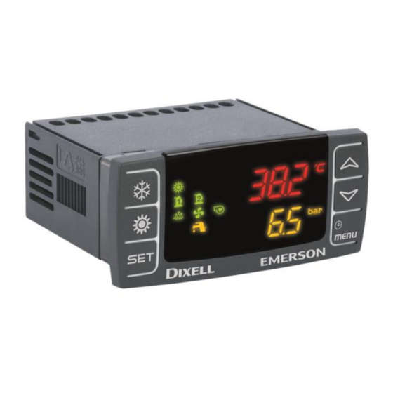
USER INTERFACE MEANING OF THE LEDS DISPLAY AND ICONS ICON MEANING / FUNCTIONNING °C °F Lighted when the display shows a temperature or pressure Lighted when the bottom display shows the clock Lighted during the programming parameters if it is time based Lighted in function menu when the display shows the defrost delay Alarm: blinking in case of alarm Lighted when sanitary hot water function is active... -
Page 9: Display Layout
Flow switch alarm / supply fan overload (air / air unit) Water pump: lighted if at least one pump is ON Condenser fan: lighted if at least one fan is ON Lighted when a compressor is ON Blinking = when the delay of activation is running Lighted when auxiliary function is active Lighted when the controller is ON in cooling or heating Lighted when the Free cooling is active... -
Page 10: Other Display Information
OTHER DISPLAY INFORMATION READ THE SET POINT VALUE Press and release the SET key: If the unit is on standby: • lower display shows SEtC (set chiller); • press SET key again, lower display shows SEtH (set heat pump, if it is enabled); •... -
Page 11: Key Combinantion
During the programming: push To enter parameter modification or confirm a value once Push when an alarm is showed in To reset the alarm menù ALrM Push once To read probes value Pushing once during To change the group of parameters, to change the programming parameter, to change the value of the parameter Push for 1 second during the... -
Page 12: First Installing
FIRST INSTALLING ON BOARD CLOCK (OPTIONAL) In case of power failure the time and date are maintained for about 3 days (at room temperature 25 °C); the display shows the message "rtC" and it is necessary to set the clock. RTC SETUP Push Menu key continuously for 3 seconds until the bottom display shows “Hour”... -
Page 13: Programming Using Local User Interface
• Select the UPL function (on the bottom display) • Push SET key and immediately the instrument starts transfer the parameters into the Hot key. During the upload the regulation is locked and the top display shows the “UPL” blinking label. At the end of the UPLOAD will appear: “End”... -
Page 14: Enter Parameters Programming Level Pr3
Push UP or DOWN to select Pr2 password Push SET and, if the value is correct, the top display shows the first family of parameters “ALL” Push UP or DOWN to select the parameter family Push SET to enter, the bottom display shows the first available parameter label while the top display shows its value Push UP or DOWN to modify its value Push SET to confirm the new value... -
Page 15: Alarm List: Read And Reset
• COSn Read and reset the number of compressor starts-up • COdt Read the compressor discharge temperature • Cond Read the condensing fan speed percentage of the proportional output • Pout Read the percentage of the proportional output 0 ÷ 10 Vdc •... -
Page 16: Remote Keyboard Vi613
To exit, push the MENU key or wait the timeout. The standard password to reset the alarm log is “4”. REMOTE KEYBOARD VI613 The display visualization and the button functions are the same of the Ichill, then refer to previous chapters of the quick reference guide. -
Page 17: Remote Lcd Panel Vgi810 Or V2I810
REMOTE LCD PANEL VGI810 OR V2I810 Two models of remote LCD panel are available; VGI810 Visograph 1st series V2I810 Visograph IInd seres The description of the user interface is available in the user manual of the Visograph. 1592022010 Quick reference guide iCHILL 100CX EVO rel. 1.0 17/40... -
Page 18: Remote Touch Panel Vtic10
REMOTE TOUCH PANEL VTIC10 The description of the user interface is available in the user manual of the Visotouch. TABLE OF THE OUTPUT STATUS IN ALARM CONDITION 15.1 M ACHINE ALARMS Alarm Alarm Comp. Heaters Support Evaporator Condenser Domestic Solar Condenser Auxiliary Code... - Page 19 ALC1 General alarm General alarm OFF (9) OFF (9) OFF (9) OFF (9) OFF (9) OFF (9) OFF (9) ALC2 type 2 Phase ALSF sequence alarm temperature of ALti the evaporator inlet (air / air unit) Alarm Probe alarm APE1 I/O Expansion probe alarm APE8...
- Page 20 Serial communication AUAL failure with IEV expansion valve driver Remote terminal AtrE Visograph 2.0 communication alarm Remote terminal VI622 Atr1 / TI620 Atr2 communication alarm (1) = the status of the load depends on wich probe is faulty; e.g. if the regulation probe is faulty main loads are OFF, if external temperature probe is faulty there is not direct actions on the loads but the dynamic set point function is disabled (2) = with probe configured as auxiliary relay control...
-
Page 21: Circuit Alarm
15.2 C IRCUIT LARM Alarm Alarm description Compressors Fan condensing Code Anti-freeze alarm in chiller mode b1AC b1Ac Anti-freeze warning in chiller Anti-freeze alarm in heat pump b1AH b1Ah Anti-freeze warning in heat pump b1dF End defrost alarm OFF after 60 b1HP High pressure switch seconds... -
Page 22: Warning
15.1 WARNING Alarm Alarm description Code AEP1 Evaporator 1 water pump maintenance AEP2 Evaporator 2 water pump maintenance ACP1 Condenser 1 water pump maintenance ACP2 Condenser 2 water pump maintenance AEun Unloading by high evaporator inlet temperature ASAn Domestic hot water pump maintenance ASUn Solar panel water pump maintenance ArtC... -
Page 23: Wiring Connections
WIRING CONNECTIONS IC106CX: H 17.1 ARDWARE ESOURCES • 6 digital outputs (relays): max current on the relay contacts relè 5(2)A 250V max current on the common line 10A 250V • 11 digital inputs free of voltage • analogue inputs: • 4 temperature probes (NTC / PTC) •... -
Page 24: Ic108Cx: Hardware Resources
IC108CX: H 17.2 ARDWARE ESOURCES • 8 digital outputs (relays): max current on the relay contacts relè 5(2)A 250V max current on the common line 10A 250V • 11 digital inputs: (free of voltage) • analogue inputs: • 4 temperature probes (NTC / PTC) •... -
Page 25: Remote Panel Connection (Vi613 Evo Or V2I810 Or Vtic10)
17.1 REMOTE PANEL CONNECTION (VI613 EVO OR V2I810 OR VTIC10) It is possible to connect to the instrument up to two remote panels VI613 available with or without temperature sensor on board, or a V2I810 LCD panel, or a touch panel VTIC10; the use of keyboards VI613 exclude the possibility of using the keyboard Visograph or Visotouch and vice versa. - Page 26 VI613 LED panel VGI810 or V2I810 LCD PANEL 1592022010 Quick reference guide iCHILL 100CX EVO rel. 1.0 26/40...
-
Page 27: Analog Inputs Ntc - Ptc Probes
VTIC10 TOUCH PANEL NTC – PTC P 17.2 NALOG NPUTS ROBES PbC = common terminal Pb1…Pb6 = probe inputs 1592022010 Quick reference guide iCHILL 100CX EVO rel. 1.0 27/40... -
Page 28: Digital Inputs
17.3 IGITAL NPUTS GND = common terminal ID1…ID11 = digital inputs 1592022010 Quick reference guide iCHILL 100CX EVO rel. 1.0 28/40... -
Page 29: Analog Input For Pressure Transducer Pp30 (4 ÷ 20Ma Signal)
17.4 30 (4 ÷ 20 NALOG NPUT FOR RESSURE RANSDUCER SIGNAL 12V = power supply for pressure transducers Pb3 and Pb4 = pressure transducer inputs 17.5 30 (0 NALOG NPUT FOR RESSURE ATIOMETRIC RANSDUCER ÷ 5V SIGNAL +5V = power supply for pressure transducers GND = ground for pressure transducers Pb3 and Pb4 = pressure transducer inputs 1592022010 Quick reference guide iCHILL 100CX EVO rel. -
Page 30: Pwm Output For Condensing Fan Speed Control
17.6 PWM O UTPUT FOR ONDENSING PEED ONTROL OUT3 and OUT4 = signals for the modulation of the condenser fan GND = ground for pressure transducers The compatible modules are the following: XV05PK mono-phase 500 Watt (2A) XV10PK mono-phase 1000 Watt (4A) XV22PK mono-phase 2200 Watt (9A) 1592022010 Quick reference guide iCHILL 100CX EVO rel. -
Page 31: Proportional Output For Fan Condensing Control Or For Compressor Inverter Controlled Or For Auxiliary Outputs
17.7 ROPORTIONAL UTPUT ONDENSING ONTROL OR OMPRESSOR NVERTER ONTROLLED OR UXILIARY UTPUTS OUT1…OUT4 = signals for the modulation of the condenser fan GND = ground for pressure transducers 1592022010 Quick reference guide iCHILL 100CX EVO rel. 1.0 31/40... -
Page 32: Proportional Output 0
17.8 0..10 PROPORTIONAL OUTPUT V TO CONTROL DUMPER MOTORS OUT1…OUT4 = signals for the modulation of the dumper motor GND = ground If the dumper motor has a common line between a pole of the power supply and the “–“ pole of the 0..10V signal, it is necessary to use two transformers for the power supply of the controller Ichill and the power supply of the dumper motor. - Page 33 1592022010 Quick reference guide iCHILL 100CX EVO rel. 1.0 33/40...
-
Page 34: Proportional Outputs Configured For Aux Relay Control
17.9 ROPORTIONAL OUTPUTS CONFIGURED FOR AUX RELAY CONTROL OUT1…OUT4 = signals for relays GND = ground 1592022010 Quick reference guide iCHILL 100CX EVO rel. 1.0 34/40... -
Page 35: Connection To The Electronic Expansion Valve Driver Iev22D Or Iev12D
IEV22D ONNECTION LECTRONIC XPANSION ALVE RIVER 17.10 IEV12D The Ichill 100CX EVO can be connected to an Eletctronic expansion valve driver IEV22D or IEV12D through LAN connection. 1592022010 Quick reference guide iCHILL 100CX EVO rel. 1.0 35/40... -
Page 36: Installing And Mounting
INSTALLING AND MOUNTING 18.1 PANEL CUT- OUT The instrument must be mounted on vertical panel with cut-out 71x29mm, and fixed using the special supplied bracket. Avoid locations subject to heavy vibration, corrosive gases or excessive dirt. Ensure ventilation around the instrument. -
Page 37: Electrical Connections
WALL MOUNTING: use the vertical V-KIT (black, white and grey) as described in the following scheme: ELECTRICAL CONNECTIONS The instrument is provided with: • 2 removable terminal blocks MOLEX MICROFIT 14 and 18 ways for power supplay / digital and analogue inputs and modulating outputs •... -
Page 38: Technical Data
TECHNICAL DATA 20.1 S UPPLY VOLTAGE Power Supply: 12Vac/dc -10% ÷ 15%, 50/60Hz, or 24Vac/dc -10% ÷ 10%, 50/60Hz Consumption: Max. 10VA Connectors: Molex connectors for power supply, probes connection, digital inputs, analog outputs) STELVIO screw connectors for LAN connection STELVIO screw connectors for relay 20.2 A NALOGUE INPUTS... -
Page 39: Analogue Outputs
(configurable via software - OUT1/OUT2: 0-10Vdc parameter) - OUT3 and OUT 3: • 0-10Vdc • PWM (to use with Dixell XV series fan controllers) Maximum load: 40mA Accuracy: ±2% full scale Note: The electrical devices controlled by these analogue outputs... -
Page 40: Characteristic Plastic Housing
20.6 C HARACTERISTIC PLASTIC HOUSING Dimensions: Frontal panel 32x74mm; depht 60mm Mounting: Panel mounting in a 29x71mm panel cut-out Material: Thermoplastic PC-ABS Selfhestinguish: V0 (UL94) IP protection: IP65 20.7 OPERATING AND STORAGE TEMPERATURE Operating temperature: -10°C ÷ 55°C Storege temperature: -30°C ÷...
Need help?
Do you have a question about the Emerson iChill IC100CX EVO and is the answer not in the manual?
Questions and answers