
Subscribe to Our Youtube Channel
Related Manuals for grandimpianti EB10


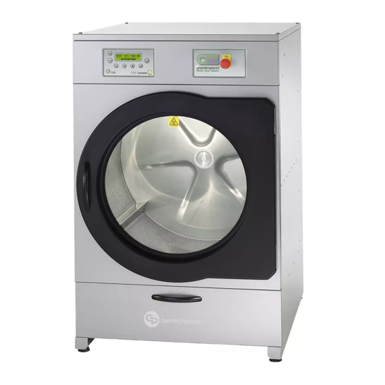
Summary of Contents for grandimpianti EB10
- Page 1 USE AND MAINTENANCE DRYER EB10 – EB15 211/C Via Masiere, 32037 - Sospirolo (bl) G400 DRY ELECTRONIC CONTROL Italy...
- Page 2 USE AND MAINTENANCE PREMISE AND WARRANTY surveillance. • Do not smoke in proximity of the appliance during use. • Do not remove or by-pass safety devices. • Never use direct or indirect jets of water on the 1.1 PREMISE machine, pay attention not to install it in proximity of We would like to thank you for the purchase of our machine.
- Page 3 attached to this manual).). recommends the use of original spare parts. To order consult - Set of stickers for the gas change, to be applied on the data the relative paragraph at the end of the manual. plate (on the machine and the manual) as indicated in the The descriptions and illustrations contained in this manual last page of this manual.
- Page 4 sequence indicated on it, block the cable using the plastic INCORRECT, REVERSE CYCLIC DIRECTION, EXTRACTION nut. WILL BE INSUFFICIENT FOR MACHINE FUNCTIONING. ATTENTION! • INFORM THE CUSTOMER, THEUSER OR THE TECHNICAL • These appliances are supplied with electronic control MANAGER OF THE LAUNDRY PLANT OF THE IMPORTANCE devices such as inverter boards: to be CE type- OF THE CORRECT CYCLIC DIRECTION OF THE PHASES SO approved, these devices must have anti-interference...
- Page 5 movement of the machine or if the machine is to be at - Keep a distance of at least 10cm in air from all parts of a standstill for a long period of time. Before connecting furniture that can be considered flammable. the appliance make sure that the plate data correspond to the features of the electricity network, which must 5.2 CONNECTION OF THE VAPOURS EVACUATION PIPE FOR...
- Page 6 • EB 10 model dryer EB 10 870 m 5.3.1.1 THERMOSTATIC TRAP WITH LIQUID DILATION • EB 15 model dryer EB 15 870 m Does not withhold condensate and is therefore not subject to freezing. High discharge capacity also when cold. The ATTENTION! minimum distance between the dryer output and the trap is •...
- Page 7 5.4 GAS CONNECTION: INSTALLATION OF THE APPLIANCE ATTENTION! WITH GAS HEATING • A bend of 90° corresponds to about on metre of linear flue. 5.4.1 TYPE OF APPLIANCE • The 10kg load model means 10kg of laundry including 50%, and not over, of relative humidity; the same rule is valid for the 15kg model i.e.
- Page 8 2) The machine performance is not optimal, thus that the diameter stated in the new nozzle that is to be lengthening drying times. mounted corresponds to the following table (see exploded We must remind of the daily frequency of these operations, diagram-gas battery page).
- Page 9 increase and anti-clockwise to decrease the pressure. 5.4.7.3 Description of the valve: 7. If the machine is powered by liquid propane gas (G30- 1. Attachment for the manometer that indicates pressure at G31), commonly called GPL or LPG, the valve must be the burner.
- Page 10 6. INDICATIONS RELATIVE TO THE MACHINE 6.2 DESCRIPTION OF THE PUSH BUTTON CONTROL PANEL 6.1 DESCRIPTION OF THE MACHINE The main parts of the machine are made up from (see fig. 1): 1) Cover under which the control circuit is located 2) Open window in the standard version.
- Page 11 supplied). 7. SPACE NECESSARY FOR THE INSTALLATION, 10) Condensate recovery line gate valve (EBV models only, USE AND MAINTENANCE OF THE MACHINE not supplied). 11) Gas supply line (EBG models only, See plate data for the The washing machine must have the minimum space indicated type of gas and power supply pressure).
- Page 12 8. DRYER FUNCTIONING ATTENTION! • This value is only the fruit of a calculation and has no 8.1 PREMISE reference to the length of the flue or any particularity Check that the gas and steam gate valves (power supply of the installation. and condensate exhaust) for the machines with this type of •...
- Page 13 KSTART pressed KMODE pressed KMODE pressed KMODE pressed With door closed...
- Page 14 INSERTION OF CORRECT PASSWORD WITHOUT CONFIRMATION USING KENT KMODE pressed KPIU With door closed pressed...
- Page 16 CYCLE IN STAND BY 3 CYCLES MENU 3.1 CYCLES: 3.1.1 CYCLE 01: COMMENT : - - - - - - - - - - - - - - - - - - - - (max 20 alphanumerical char.) HEAT TEMPERATURE: 0 - 140 C MAINTENANCE: 0 - 120 min HYSTERISIS: 2 - 10 C HEATING POWER: 70 - 100%...
- Page 17 Once the cycle has been selected on the basis of the At the same time the START/STOP button is pressed, the time temperatures and the specific movement (see the successive starts to decrease that indicates how much time remains until description of the work cycles) considering the various type the end of the cycle.
- Page 18 8.2 CYCLE PHASES indicates filter is completely clean. The different phases are indicated by the control display and In this condition, press the “ENTER” button. A window opens in particular: that allows to freely set the following values: • work temperature 1) HEATING - The machine heats the air to the temperature •...
- Page 19 reset and the memory cleaned. • Contact the dealer or the after-sales service if machine 5. On insertion of the smartcard, as a third option as well programming must be modified using this system. as that of choosing from downloading the data or saving them in the card (right or left arrow)it is also possible 8.6 RECOMMENDATIONS FOR USING THE MACHINE to format the smartcard;...
- Page 20 9. SAFETY PROCEDURES ATTENTION! • This manual must be kept with the appliance, and must During appliance functioning some conditions may occur, accompany it for its entire lifespan. indicating a relative alarm signal if an anomaly is present. • Do not use anti-static products or detergents unless The code appears flashing on the display.
- Page 21 9.2 DETAILED DESCRIPTION OF THE ALARMS WITH WHICH THE MACHINE IS SUPPLIED ALARM E1 EXTRACTION MOTOR CIRCUIT BREAKER DESCRIPTION ON DISPLAY E1: extraction motor overload DESCRIPTION There has been over-heating/overloading or a short circuit of the extraction motor. BUZZER ACTIVATION The activation of the BUZZER is envisioned immediately.
- Page 22 ALARM E3 FILTER HATCH MICRO SWITCH DESCRIPTION ON DISPLAY E3: filter open DESCRIPTION If the filter hatch is opened during machine functioning then all relays must be disabled except the cycle relay and the display shows “E3: filter open”. The machine continues to display this condition until the hatch is closed.
- Page 23 For safety reasons the management of the no flame alarm is double, i.e. via the control unit and via G400 control. The two control systems in this case are not connected and therefore it is necessary to act on both controls in order to go back to the working condition.
- Page 24 ALARM E6 PT1000 N°1 AND N°2 TEMPERATURE PROBE DESCRIPTION ON DISPLAY E6: over-heating T1 E6: over-heating T2 If the TEMP1 temperature probe is not connected or if a temperature higher than 170°C is measured, all functions are disabled. Any cycle in progress is aborted, the display shows “E6: over-heating T1”.
- Page 25 ALARM E8 HEATING ANOMALY DESCRIPTION ON DISPLAY E8: Heating anomaly If TEMP1 reads a temperature higher than 25°C with respect to the set point, the cycle is aborted and the display shows “E8: Heating anomaly”. DESCRIPTION This control is only performed with the cycle in progress and only in the heating phase. It is NOT managed in the cooling phase.
- Page 26 ALARM MOTOR PROTECTION INTERVENTION WITH ALARMS IN AUTORESET 1 “EF Motor anomaly” 2 “OC Motor over-current” DESCRIPTION ON DISPLAY 3 “OV Motor over-voltage” 4 “UV Over-voltage UV” 5 “OCH Motor anomaly” 6 “ST Motor anomaly” These 6 alarms are shown on the display according to their intervention with decreasing priority. DESCRIPTION Once the inverter has entered error conditions it awaits the automatic reset from the G400 DRY control.
- Page 27 1 “OH Inverter over-heating”: The machine must be installed in a place that respects the plate data. Check cleanliness and functioning of the inverter cooling fans 2 “OLi Inverter over-loading”: Optimise the load of laundry. 3 “OLM Motor overloading”: Optimise the load of laundry. 4 “OLR Braking overload”: Optimise the load of laundry.
- Page 28 • The amount of laundry loaded is much lower than that board. indicated in the technical data table. • Clean the heating resistance fins or of the steam battery • The steam pressure is too high (for steam heating or of the gas burner, without using aggressive chemicals models).
- Page 29 11. INDICATIONS FOR PUTTING OUT OF SERVICE, DISASSEMBLY AND ELIMINATION OF THE MACHINE 11.1 PREMISE When the appliance is no longer to be used, it must be made non-operational, eliminating the materials and keeping that already stated in the “Transport and installation” paragraph in mind.
- Page 30 12. DESCRIPTION OF THE PRESET CYCLES From cycle 11onwards they are all free. However, the preset cycles can be modified at any time. DRYER 10 – 15kg electric and steam DRYING Cooling Motor Cycle Cycle name Time Temperature Hysterisis Power Time Temperature Work...
- Page 31 Medium dynamic Intensive Heavy intensive Mixed synthetic DRYER 10 – 15kg electric COIN OPERATED DRYING Cooling Motor Cycle Cycle name Time Temperature Hysterisis Power Time Temperature Work Pause Speed number time time min. ºC ºC min. ºC Heavy cotton Cotton Towelling Synthetic Delicate...
- Page 32 Type of laundry Drum rotation Program to dry and Drying time every Drum speed* Cool down number. description of inversion time. the cycle. min. ºC Sec. r.p.m. min. Cotton shirts Wool Merinos Coats jackets Quilted jackets Windcheaters *the speed must always be calibrated manually depending on the effective load of laundry. To have less mechanical action, increase the number of r.p.m.
- Page 33 13. COIN OPERATED/CENTRAL PAYMENT UNIT For example, in the case indicated above regarding 3 payments, VERSION the heating time becomes 3x with JUST ONE cooling cycle at the end. 13.1 BOARD SETTING Using dip switch n°3 the machine can be enabled to function 13.3 INDICATIONS ON DISPLAY by means of a mechanical or electronic coin operated device.
- Page 34 13.4.3 ELECTRONIC COIN OPERATION ON THE MACHINE NOTE The display shows the price and cycle selected with a display See also coin operation setting inthe previous paragraph. that is: In both cases it must be possible to reset the residual credit Pxx :(program number from 01 to 20) with the machine in IDLE-ON and door open by pressing the Cycle cost: xx,xx €...
- Page 35 POWER LAYOUT EBE10-15 28/10/2008 G.Porta Schema di potenza, collegamento 230/1/50 , 230/1/50 UK , 230/3/50-60 , 400/3/50-60 , 440/3/60...
- Page 36 WIRING DIAGRAM...
- Page 37 COMPONENTS KEY RESET GAS STATUS SIGNAL RELAY (SELF SERVICE ONLY) FLAME-CONTROL CONTROL UNIT DRIVE DRUM MOTOR INVERTER ELECTRONIC COIN OPERATION STEAM ELECTROVALVE 5X20 800MA FUSE 5X20 2A FUSE 5X20 630MA FUSE 5X20 630MA FUSE INTAKE TIMER (NO) NOT USED NOT USED ELECTRIC HEATING TIMER MOT 1 DRUM MOTOR...
- Page 39 INDEX 6.3 COMPLETE RANGE OF THE APPLICATIONS ........PAGE 6.4 INFORMATION REGARDING THE ELECTRIC PLANT ..1. PREMISE AND WARRANTY ....................1.1 PREMISE 7. SPACE NECESSARY FOR THE INSTALLATION, USE AND ............................. 1.2 PRESCRIPTIONS AND RECOMMENDATIONS MAINTENANCE OF THE MACHINE ........
- Page 40 13. COIN OPERATED/CENTRAL PAYMENT UNIT VERSION ..........................13.1 BOARD SETTING ......................13.2 VERSIONS ..........................13.2.1 MULTIPLE PAYMENT ..................13.3 INDICATIONS ON DISPLAY ................13.3.1 COIN OPERATION WITH STEPPER ..........13.3.2 EXTERNAL COIN OPERATION OR WITH CENTRAL PAYMENT UNIT ....................... 13.3.3 ELECTONIC COIN OPERATION MACHINE...
- Page 41 TARGHETTA TECNICA, RATING PLATE, PLAQUETTE TECHNIQUE, GER˜TESCHILD, PLACA DE CARACTER˝STICAS MODELLO MODEL NR. MATR. SERIAL NR. ALIM. EL. EL. POWER POTENZA TOT. TOTAL INPUT PRESSIONE VAPORE STEAM PRESSURE ATTENZIONE! E’ OBBLIGATORIO IL COLLEGAMENTO A TERRA CAUTION! THE APPLIANCE MUST BE CONNECTED TO EARTH RIVENDITORE, DISTRIBUTOR, REVENDEUR, VERTRIEB, REVENDEDOR ASSISTENZA TECNICA, AFTER-SALES SERVICE,...
Need help?
Do you have a question about the EB10 and is the answer not in the manual?
Questions and answers