Nikon COOLPIX S1 Repair Manual
Hide thumbs
Also See for COOLPIX S1:
- User manual (110 pages) ,
- Instruction manual (2 pages) ,
- Owner's manual (110 pages)

Related Manuals for Nikon COOLPIX S1


Summary of Contents for Nikon COOLPIX S1
- Page 1 VAA35001-R.3666.A 作成承認印 配布許可印 VAA35001 REPAIR MANUAL Copyright c 2005 by Nikon Corporation. All Rights Reserved. 無断転載を禁ず !! Printed in Japan April 2005 Downloaded from www.Manualslib.com manuals search engine...
- Page 2 VAA35001-R.3666.A CONTENTS SPECIFICATIONS ・・・・・・・・・・・・・・・・・・・・・・・・・・・・・・・・・・・・・・・・・・・・・・・・・・・・・・・・・・・・・・・・・・・・・・・・・ M1-M2 DISASSEMBLY WARNING・・・・・・・・・・・・・・・・・・・・・・・・・・・・・・・・・・・・・・・・・・・・・・・・・・・・・・・・・・・・・・・・・・・・・・・・・・・・・・・・・・ D1 REAR COVER ・・・・・・・・・・・・・・・・・・・・・・・・・・・・・・・・・・・・・・・・・・・・・・・・・・・・・・・・・・・・・・・・・・・・・・・・・・・・・・ D2 LCD ・・・・・・・・・・・・・・・・・・・・・・・・・・・・・・・・・・・・・・・・・・・・・・・・・・・・・・・・・・・・・・・・・・・・・・・・・・・・・・・・・・・・・・・ D3 MONITOR HOLDER ・・・・・・・・・・・・・・・・・・・・・・・・・・・・・・・・・・・・・・・・・・・・・・・・・・・・・・・・・・・・・・・・・・・・・・・・・ D4 CARD HOLDER ・・・・・・・・・・・・・・・・・・・・・・・・・・・・・・・・・・・・・・・・・・・・・・・・・・・・・・・・・・・・・・・・・・・・・・・・・・・・・ D5 DISCHARGE OF MAIN CONDENSER ・・・・・・・・・・・・・・・・・・・・・・・・・・・・・・・・・・・・・・・・・・・・・・・・・・・・・・・・・・ D6 PLACE WHICH MUST NOT BE TOUCHED IN LENS UNIT・・・・・・・・・・・・・・・・・・・・・・・・・・・・・・・・・・・・・・・・・ D7 FRONT COVER ・・・・・・・・・・・・・・・・・・・・・・・・・・・・・・・・・・・・・・・・・・・・・・・・・・・・・・・・・・・・・・・・・・・・・・・・・・・・・ D7 STAND・・・・・・・・・・・・・・・・・・・・・・・・・・・・・・・・・・・・・・・・・・・・・・・・・・・・・・・・・・・・・・・・・・・・・・・・・・・・・・・・・・・・・...
- Page 3 VAA35001-R.3666.A ADJUSTMENT ・・・・・・・・・・・・・・・・・・・・・・・・・・・・・・・・・・・・・・・・・・・・・・・・・・・・・・・・・・・・・・・・・・・・ A16-A26 DESCRIPTION OF CIRCUIT ・・・・・・・・・・・・・・・・・・・・・・・・・・・・・・・・・・・・・・・・・・・・・・・・・・・・・・・・・・・・・・・・ E1-E8 ELECTRICITY OVERALL WIRING ・・・・・・・・・・・・・・・・・・・・・・・・・・・・・・・・・・・・・・・・・・・・・・・・・・・・・・・・・・・・・・・・・・・・・・・・・・ E9 CP1(DMA) CIRCUIT DIAGRAM ・・・・・・・・・・・・・・・・・・・・・・・・・・・・・・・・・・・・・・・・・・・・・・・・・・・・・・・・・・・・・ E10 CP1(SYA) CIRCUIT DIAGRAM ・・・・・・・・・・・・・・・・・・・・・・・・・・・・・・・・・・・・・・・・・・・・・・・・・・・・・・・・・・・・・・ E11 CP1(PWA) CIRCUIT DIAGRAM・・・・・・・・・・・・・・・・・・・・・・・・・・・・・・・・・・・・・・・・・・・・・・・・・・・・・・・・・・・・・・ E12 CP1(STA) CIRCUIT DIAGRAM ・・・・・・・・・・・・・・・・・・・・・・・・・・・・・・・・・・・・・・・・・・・・・・・・・・・・・・・・・・・・・・ E13 TB1 CIRCUIT DIAGRAM ・・・・・・・・・・・・・・・・・・・・・・・・・・・・・・・・・・・・・・・・・・・・・・・・・・・・・・・・・・・・・・・・・・・ E14 CA1 CIRCUIT DIAGRAM ・・・・・・・・・・・・・・・・・・・・・・・・・・・・・・・・・・・・・・・・・・・・・・・・・・・・・・・・・・・・・・・・・・・ E15 OVERALL BLOCK DIAGRAM・・・・・・・・・・・・・・・・・・・・・・・・・・・・・・・・・・・・・・・・・・・・・・・・・・・・・・・・・・・・・・・...
-
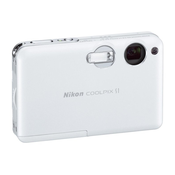
Page 4: Specifications
VAA35001-R.3666.A SPECIFICATIONS Type COOLPIX S1 digital camera Effective pixels 5.1 million 1/2.5” CCD; total pixels: 5.36 million Image size (pixels) 2,592 × 1,944 (2592*, 2592) 2,048 × 1,536 (2048) 1,024 × 768 (1024) 640 × 480 (640) Lens 3 × Zoom Nikkor ED lens Focal length F=5.8 - 17.4 mm... - Page 5 Supported languages Chinese (Simplifi ed and Traditional), Dutch, English, French, German, Italian, Japanese, Korean, Russian, Spanish, Swedish Power sources ・One rechargeable Nikon EN-EL8 lithium-ion battery (supplied) ・EH-63 AC adapter (supplied) Battery life Approx. 200 shots (EN-EL8; based on CIPA standard *) Dimensions (W ×...
- Page 6 VAA35001-R.3666.A DISASSEMBLY ������� � ����������������������������������������������������������������������� �������������������������� ������������������������������������������������������������������ ������������������������������������������������� Points to notice for Lead-free solder products ・ Lead-free solder is used for this product. ・ For soldering work, the special solder and soldering iron are required. ・ Do NOT mix up lead-free solder with traditional solder. ・...
-
Page 7: Rear Cover
VAA35001-R.3666.A REAR COVER ・ Remove 4 screws [#102]. ・ Remove 2 screws [#101]. Screw [#101] Screw [#102] Screw [#102] ・ Remove 4 screws [#102]. ・ Unhook the rear cover [#029] and open the rear cover [#029]. ・ Remove the FPC from the connector. Hook Screw [#102] Screw [#102]... - Page 8 VAA35001-R.3666.A ・ Unhook and lift up the LCD [#008]. LCD [#008] Hook Hook ・ Remove the connector and the FPC. Connector - D3・ S1 - Downloaded from www.Manualslib.com manuals search engine...
-
Page 9: Monitor Holder
VAA35001-R.3666.A MONITOR HOLDER ・ Remove the bosses from the side ornament [#002] and pull it out in the arrow direction. Monitor holder [#001] Side ornament [#002] Boss ・ Remove 2 screws [#103]. ・ Remove the monitor holder [#001]. ・ Remove the strap shaft [#018]. Monitor holder [#001] Strap shaft [#018] Screw [#103]... -
Page 10: Card Holder
VAA35001-R.3666.A CARD HOLDER ・ Pull out the card holder [#014] in the arrow direction. Card holder [#014] - D5・ S1 - Downloaded from www.Manualslib.com manuals search engine... - Page 11 VAA35001-R.3666.A ������� � ����������������������������������������������������������������������� �������������������������� ������������������������������������������������������������������ ������������������������������������������������� DISCHARGE OF MAIN CONDENSER ・ Take off the spacer [#229]. Spacer [#229] ・ Carry out discharging. 2K Ω /5W - D6・ S1 - Downloaded from www.Manualslib.com manuals search engine...
-
Page 12: Front Cover
VAA35001-R.3666.A PLACE WHICH MUST NOT BE TOUCHED IN LENS UNIT PLACE WHICH MUST NOT BE TOUCHED IN LENS UNIT <LENSの触れてはいけない箇所> Shutter connector unit シャッタコネクタ部 モータ部 Motor unit G1 ~ Prism unit G1~プリズム部 PI unit Rear sheet PI部 背面シート FRONT COVER ・... - Page 13 VAA35001-R.3666.A STAND ・ Remove the screw [#101]. ・ Remove the screw [#103]. ・ Remove the stand [#203]. Stand [#203] Screw [#103] Screw [#101] - D8・ S1 - Downloaded from www.Manualslib.com manuals search engine...
- Page 14 VAA35001-R.3666.A BARRIER MOTOR UNIT ・ Remove 2 screws [#103]. ・ Remove the barrier motor unit [#206]. Screw [#103] Barrier motor unit [#206] ・ Remove the shaft [#205]. ・ Remove the lens cover [#204]. Lens cover [#204] Shaft [#205] ・ Take off the spacer [#239]. Barrier motor unit [#206] Spacer [#239] - D9・...
-
Page 15: Battery Holder
VAA35001-R.3666.A BATTERY HOLDER ・ Open the battery cover [#230]. ・ Remove the screw [#103]. ・ Unhook at 4 places and remove the battery holder [#238]. Screw [#103] Battery holder [#238] Hook Battery cover [#230] Hold the inside of the battery holder [#238] by fingers, in order to make it easier to unhook the battery holder [#238]. - Page 16 VAA35001-R.3666.A SPEAKER/MICROPHONE ・ Remove the screw [#104]. ・ Remove the speaker holder [#216]. ・ Take off the spacer [#217] from the speaker holder [#216]. ・ Take off the spacer [#220] and remove the microphone [#221]. ・ Take off the spacer [#222]. ・...
- Page 17 VAA35001-R.3666.A PLACE WHICH MUST NOT BE TOUCHED IN LENS UNIT レンズユニットの触れてはいけない箇所 <LENSの触れてはいけない箇所> Shutter connector unit シャッタコネクタ部 モータ部 Motor unit G1 ~ Prism unit G1~プリズム部 MAIN PCB UNIT CP-1 PI unit Rear sheet PI部 背面シート ・ Remove the FPC. ・ Remove the connector. ・...
-
Page 18: Flash Unit
VAA35001-R.3666.A LED PCB UNIT TB-1 ・ Remove the spring [#214] by releasing it from bosses. ・ Remove the spacer [#212]. ・ Remove the LED PCB unit TB-1 [#213]. Spring [#214] Spacer [#212] LED PCB unit TB-1 [#213] Boss LED PCB unit TB-1 [#213] FLASH UNIT ・... - Page 19 VAA35001-R.3666.A ASSEMBLY Note: Before replacing the lens unit or the main PCB unit CP-1 [#225] with a new one, be sure to take a note of the value, because it will be used for adjusting the lens after the assembly. Be sure to take a note of this value.
- Page 20 VAA35001-R.3666.A PLACE WHICH MUST NOT BE TOUCHED IN LENS UNIT PLACE WHICH MUST NOT BE TOUCHED IN LENS UNIT <LENSの触れてはいけない箇所> Shutter connector unit シャッタコネクタ部 モータ部 Motor unit G1 ~ Prism unit G1~プリズム部 PI unit Rear sheet PI部 背面シート LED PCB UNIT TB-1 ・...
- Page 21 VAA35001-R.3666.A MAIN PCB UNIT CP-1 ・ Solder the lead wires [red] and [black]. ・ Set the connector. ・ Set the FPC. Lead wire [black] Main PCB unit CP-1 [#225] Lead wire [red] Connector - A3・ S1 - Downloaded from www.Manualslib.com manuals search engine...
- Page 22 VAA35001-R.3666.A SPEAKER/MICROPHONE ・ Solder the FPC onto the speaker [#218]. (Fig. 1) ・ Adhere the spacer [#219]. ・ Set the speaker [#218]. ・ Solder the lead wires [red] and [black] onto the FPC. (Fig. 2) ・ Adhere the spacer [#222]. ・...
- Page 23 VAA35001-R.3666.A CONTROL TOP UNIT ・ Set the control top unit [#223]. Control top unit [#223] ・ Tighten 2 screws [#103]. Boss Hook Screw [#103] - A5・ S1 - Downloaded from www.Manualslib.com manuals search engine...
- Page 24 VAA35001-R.3666.A ASSEMBLY OF BATTERY HOLDER ・ Adhere the label [#236] on the battery holder. ・ Pass the shaft [#233] through the battery holder [#238], the inner cover [#231] and the spring [#232]. Then, insert the end of the spring [#232] into the holes of the inner cover [#231] and the battery holder [#238]. (Fig. 1) ・...
- Page 25 VAA35001-R.3666.A BATTERY HOLDER ・ Hook the battery holder [#238] to the battery cover at 4 places. ・ Tighten the screw [#103]. Screw [#103] Battery holder [#238] Hook Battery cover [#230] - A7・ S1 - Downloaded from www.Manualslib.com manuals search engine...
- Page 26 VAA35001-R.3666.A BARRIER MOTOR UNIT ・ Adhere the spacer [#239] onto the barrier motor unit [#206]. Barrier motor unit [#206] Spacer [#239] ・ Set the lens cover [#204]. ・ Set the shaft [#205]. ・ Set the barrier motor unit [#206]. ※ Put the section “A” of the barrier motor unit [#206] into the section “B” of the front cover [#201]. Barrier motor unit [#206] Lens cover [#204] Shaft [#205]...
- Page 27 VAA35001-R.3666.A ・ Tighten 2 screws [#103]. ・ Open and close the lens cover [#204] by fingers to check its operation. ※ Do NOT slacken the section “A” of the FPC. Lens cover [#204] Barrier motor unit [#206] Open and close the lens cover to check its operation.
- Page 28 VAA35001-R.3666.A FRONT COVER PLACE WHICH MUST NOT BE HELD IN LENS UNIT <LENSの触れてはいけない箇所> ・ Fit the multi-connector terminal at the bottom of the main PCB unit CP-1 [#225] into the front cover [#201]. Shutter connector unit シャッタコネクタ部 Then, assemble the main PCB unit CP-1 [#225] into the Motor unit モータ部...
- Page 29 VAA35001-R.3666.A ASSEMBLY OF CARD HOLDER ・ Set the SD card cover [#017] onto the card holder ・ Set the card shaft [#015]. [#014]. SD card cover [#017] Card shaft [#015] Card holder [#014] Card holder [#014] ・ Assemble the shaft [#012] and the spring [#011]. ・...
- Page 30 VAA35001-R.3666.A CARD HOLDER ・ Set the card holder [#014]. Card holder [#014] - A12 ・ S1 - Downloaded from www.Manualslib.com manuals search engine...
- Page 31 VAA35001-R.3666.A MONITOR HOLDER ・ Set the strap shaft [#018]. ・ Set the monitor holder [#001] by aligning with the bosses. ・ Tighten 2 screws [#103]. Monitor holder [#001] Strap shaft [#018] Screw [#103] Boss ・Fit the bosses of the side ornament [#002] into the holes of the monitor holder [#001] to assemble them. Monitor holder [#001] Side ornament [#002] Boss...
- Page 32 VAA35001-R.3666.A ・ Set the FPC and the connector. ・ While folding the FPC as shown below, hook the LCD [#008]. Connector LCD [#008] Hook Hook - A14 ・ S1 - Downloaded from www.Manualslib.com manuals search engine...
- Page 33 VAA35001-R.3666.A REAR COVER ・ Set the FPC. ・ Tighten 4 screws [#102]. ・ Set the rear cover [#029]. Screw [#102] Screw [#102] Rear cover [#029] ・Tighten 4 screws [#102]. ・Tighten 2 screws [#101]. Screw [#101] Screw [#102] Screw [#102] - A15 ・ S1 - Downloaded from www.Manualslib.com manuals search engine...
- Page 34 VAA35001-R.3666.A ADJUSTMENT 1. Equipment IBM compatible PC/AT ・ AC adapter EH-63 ・ USB cable ( UC-E10) ・ Cradle (COOL-STATION MV11) 2. Servicing tools ・ Pattern box ・ Color meter ・ Luminance meter ・ Calibration software (J65078) ・Adjustment collimator (J63090) 3. Adjustment / Order Adjustment after replacing the CP-1 PCB of RP 1.
- Page 35 VAA35001-R.3666.A 4. Initial image data writing and Firmware updating Write the data of initial images, and go on to update the firmware. Device ・ AC adapter (EH-63) ・ Updating SD card × 1 [How to create an updating SD card] 1) Format SD card on PC.
- Page 36 VAA35001-R.3666.A ・ When the data writing is completed, the menu for updating will be displayed. (Fig.3) (Fig.3) ・ Select "Yes", and press the decision button to update. (Fig.4) Note: Do NOT turn power OFF during updating. (Fig.4) ・ When the completion of firmware updating is displayed on the screen, turn off the camera and remove the SD card. (Fig. 5) ・...
-
Page 37: Installing Usb Driver
・ Copy "DscCalDi.exe, Camapi32.dll" folder of the floppy disk drive in any folder on the hard disk. 6. Installing USB driver If the USB driver is necessary, install Nikon View via CD-ROM packed with the camera. - A19 ・ S1 - Downloaded from www.Manualslib.com... -
Page 38: Pattern Box
VAA35001-R.3666.A 7. Pattern box Before using the pattern box, turn its power on to carry out "Aging" approx. 30 minutes: the color temperature should be adjusted to 3100 ± 20K by the color meter, and the luminance should be adjusted to 900 ± 20cd/m by the luminance meter. - Page 39 VAA35001-R.3666.A 9. Connecting the camera to the computer 1) Connect the camera to the cradle. 2) Insert the camera connector of the USB cable into the USB port connector of the cradle. 3) Connect the cable to the USB port on PC. Supply the power from the AC adapter EH-63.
-
Page 40: Lens Adjustment
VAA35001-R.3666.A 11. Lens adjustment [Preparations] ・ Turn on the collimator (J63090). (Do not connect the USB cable to PC yet.) ・ Turn on the camera. ・ Check the positions so that the chart center in the collimator should be at the center of the screen. ・... - Page 41 VAA35001-R.3666.A ・ Click "Focus", then "Yes". ・ Lens adjustment value will appear on the screen. Judgment standard: xd00 = ±55, xd01 =± 55, xd02 =± 55, xd03 =± 55, xd04 =± 55, xd05 =± 55, △(Revision) xd06 =± 55 △(Revision) ・...
- Page 42 VAA35001-R.3666.A 12. AWB adjustment [Preparations] ・ Pattern Box (Color temperature: 3100 ± 20K, Luminance: 900 ± 20cd/m [Conditions] ・ Set the pattern box and camera (lens front) as near as possible between them (approx.7 cm). ※ Set the camera and the pattern box so that their viewer surfaces should be perpendicular to each other. Note) Do not allow outside light to enter in.
- Page 43 VAA35001-R.3666.A <FIG-2> CCD Defect CCD Black - A25 ・ S1 - Downloaded from www.Manualslib.com manuals search engine...
-
Page 44: Usb Storage Information Registration
2. Double-click on the "DscCa1Di.exe". 3. Click on the "Get" button in the USB storage window and check the USB storage data. VID: NIKON PID: NIKON DSC S1 Serial: Rev. : 1.00 4. Check the "Serial" in the above USB storage data. If the displayed value is different from the serial number of the bottom of the camera, enter the number of the bottom of the camera, and click the "Set"... - Page 45 VAA35001-R.3666.A - E1・ S1 - Downloaded from www.Manualslib.com manuals search engine...
- Page 46 VAA35001-R.3666.A - E2・ S1 - Downloaded from www.Manualslib.com manuals search engine...
- Page 47 VAA35001-R.3666.A - E3・ S1 - Downloaded from www.Manualslib.com manuals search engine...
- Page 48 VAA35001-R.3666.A - E4・ S1 - Downloaded from www.Manualslib.com manuals search engine...
- Page 49 VAA35001-R.3666.A - E5・ S1 - Downloaded from www.Manualslib.com manuals search engine...
- Page 50 VAA35001-R.3666.A - E6・ S1 - Downloaded from www.Manualslib.com manuals search engine...
- Page 51 VAA35001-R.3666.A - E7・ S1 - Downloaded from www.Manualslib.com manuals search engine...
- Page 52 VAA35001-R.3666.A - E8・ S1 - Downloaded from www.Manualslib.com manuals search engine...
-
Page 53: Overall Wiring
VAA35001-R.3666.A 総合結線図 OVERALL WIRING CL306 LED_A JW601 LED_A CN110 CL305 LED_C JW602 LED_C USB_VDD USB D(-) USB D(+) & VIDEO VBAT(-) VIDEO AUDIO AV_JACK VBAT(+) CL503 BATT+ BATTERY CL504 BATT- CL505 BATTEMP CN951 VOUT STM2-1B W1400 XAN (PINK) STM2-2A (DMA) FLASH STM2-1A STM2-2B... - Page 54 VAA35001-R.3666.A CP1(DMA) 回路図 CP1(DMA) CIRCUIT DIAGRAM DMA(MAIN) DMA(LCD) VDD3 D1-01600/SX78D-JNK 1AV4J11B6390M CN143 DATA3 COMMAND R1710 2.2;1/16J ZCCE1 CLOCK TO LCD VDD3 DATA0 1AV4J11VE330G LCDD0 CN171 DATA1 LCDD1 1608 R1001 DATA2 LCDD2 0;1/16Z R1002 CARD VDD1.4 LCDD3 CK1E105KGQBNG 1608 0;1/16Z RB101 C1701 R1434 CARD/WP...
- Page 55 VAA35001-R.3666.A CP1(SYA) 回路図 CP1(SYA) CIRCUIT DIAGRAM Y1-01600/SX78D-JNK VDD5 TO MDA(MAIN) AFLED_CTL BOOST5.3V BOOST5.3V ALWAYS3.2V SW3.2V BACK UP3.2V R3021 CL306 LED_A 0;1/16Z TO TB1 BATTEMP JW601, JW602 TEMPLENS R3013 R3014 R3015 CL305 LED_C BATCHGI 22;1/16J 22;1/16J 18;1/16J TIMEOUT ZCARD Q3005 EMH10 PAON2 COMREQ R3016...
- Page 56 VAA35001-R.3666.A CP1(PWA) 回路図 CP1(PWA) CIRCUIT DIAGRAM P1-01600/SX78D-JNK F5004 �������� ���� ����� ��� �� F47K2R0C3LFND UNREG_ST TIMEOUT TO DMA(MAIN) TO DMA(MAIN) UNREG(ST) 1608 BATCHGERR 2A 32V BATCHGI D52LC <BOOST/LENS> F5003 D5301 DCIN L5301 F47K2R0C3LFND 10;M SD833-04(SC) BOOST5.3V 1608 1608 D5201 L5202 2A 32V SD833-04(SC) 1AV4L3DZ300PG...
- Page 57 VAA35001-R.3666.A CP1(STA) 回路図 CP1(STA) CIRCUIT DIAGRAM STROBO UNIT FLASH REFLECTOR S1-01600/SX78D-JNK D5403 D5402 RR264M-400 CRF02-Q W1400 PINK OM/ORDD44Z OM/ORDD44Z 290V T5402 1AV4L17B0330G OM/ORZL17B0330GZ 3316 T5401 TTR-1026R-01 C5410 W1600 GRAY 0.033;350H 1AV4L17B0310G UNREG(ST) TO DMA(MAIN) UNREG(ST) 3216 C5411 0.01;630H BLACK W1500 R5406 C5403 0.01;B...
- Page 58 VAA35001-R.3666.A TB1 回路図 TB1 CIRCUIT DIAGRAM D6001 D6001 LTLOH9203-2 JW601 TO SYA LED_A CL305, CL306 JW602 LED_C T1-01600/SX78D-JNK - E14 ・ S1 - Downloaded from www.Manualslib.com manuals search engine...
- Page 59 VAA35001-R.3666.A CA1 回路図 CA1 CIRCUIT DIAGRAM R9001 0;1/16Z +12V(A) R9007 3.3;1/16J -6.0V(A) C1-01600/SX78D-JNK +3.45V(A) �������� ���� ����� ��� �� TO CP1(DMA) CN101 C9026 +3.0V(A) R9011 +3.0V(A) 0;1/16Z +12V(A) 22 21 20 19 18 17 16 15 +12V(A) XSUB XSUB ���� IC901 XSG2A ����...
-
Page 60: Overall Block Diagram
VAA35001-R.3666.A 総合ブロック図 OVERALL BLOCK DIAGRAM CCD BLOCK LENS BLOCK BARRIER IC903 IC905 IC901 MOTOR 5M Pixel CDS, AGC, A/D C IC951 H. DRIVER V. DRIVER LENS LENS DRIVER MOTOR CN101 SYA BLOCK IC121 PROGRAM FD [0:7] FLASH (NAND) D [0:15] 128Mbit CN301 RELEASE UNIT... -
Page 61: Asic Block Diagram
VAA35001-R.3666.A ASIC ブロック図 ASIC BLOCK DIAGRAM IC101 ASIC SDRAM 256Mbit SDRAM DIGITAL CONTROLLER BLOCK CLAMP SIGNAL SRAM PROCESSOR SRAM JPEG AF,AE,AWB CONTROLLER UART COMPOSITE VIDEO NTSC/PAL SRAM ENCODER CONNECTOR DIGITAL 8bit DATA SD CARD AUDIO DRIVER IC301 98MHz MICRO 48MHz DRIVER BUS I/F CLKGEN... -
Page 62: Ccd Block Diagram
VAA35001-R.3666.A CCD ブロック図 CCD BLOCK DIAGRAM - E18 ・ S1 - Downloaded from www.Manualslib.com manuals search engine... -
Page 63: Lens Block Diagram
VAA35001-R.3666.A LENS ブロック図 LENS BLOCK DIAGRAM BARRIER BLOCK CN952 UNREG IC531 BOOST5.3V SW REG. BRPI (IC101 205pin) BR_PI Q9503 BRDET (IC101 301pin) BR_DET_SW PISW Q9502 (IC101 197pin) BR.M ZPI2 (IC101 204pin) Q9501 FPI3 LENS BLOCK VDD3 (IC101 202pin) CN951 TEMPLENS (IC301 60pin) IC951 UPD168117FC-BA2-E1-A... - Page 64 VAA35001-R.3666.A SYSTEM CONTROL ブロック図 SYSTEM CONTROL BLOCK DIAGRAM BOOST5.3V UNREG(SY) BOOST5.3V TO DMA(MAIN) BATCHGI BAT_CHG I ALWAYS3.2V BATCHGERR BAT CHG ERR TIMEOUT TIME OUT BATCHGON BAT_CHG ON Q3001 IC302 DCIN DC IN BATTERY P ON BACKUP Q3003 RESET PAON PA ON ST_CHG ON BAT_OFF VMONIT...
-
Page 65: Power Block Diagram
VAA35001-R.3666.A POWER ブロック図 POWER BLOCK DIAGRAM - E21 ・ S1 - Downloaded from www.Manualslib.com manuals search engine... - Page 66 F5004 VAA35001-R.3666.A FUSE ARRANGEMENT (CP1 PCB) F5002 F5005 F5004 F5001 F5003 F5002 F5005 FUSE Function of FUSE Phenomenon when FUSE has blown out Rating Used to protect the unit when the DC/DC converter F5001 The power is not turned on. 32V/2.5A circuit malfunctions.
- Page 67 VAA35001-R.3666.A Contents Inspection standards and Tools for S1 [1] Inspection standards ............................R1 to R10 [2] Tools ..................................T1 to T5 - S1 - Downloaded from www.Manualslib.com manuals search engine...
-
Page 68: Inspection Standards
VAA35001-R.3666.A INSPECTION STANDARDS Item Criteria Tools External view Gap/Difference in ・ General components Visual check height Gap: 0.3mm or less Difference in steps (height): 0.15mm or less ※ The 0.2mm convex section on the strap is excluded. ・ When the battery case is opened/closed: Gap in its periphery: 0.15mm or less Gap in the bottom: 0.2mm or less Difference between right and left:... - Page 69 VAA35001-R.3666.A Item Criteria Tools Operationality Operation touch ・ No uncomfortable feeling when operating a lever or knob by hand. (Make a check with hands in actual operation by following the shooting procedure.) Battery cover ・ No excessive gap when closed. ・...
- Page 70 VAA35001-R.3666.A Barrier ・ When power is ON: Proper opening. Viewed from the front of the unit, the barrier is completely unseen at the cover opening window and fully hidden. ・ When power is OFF: Proper closing. Viewed from the front of the unit, the edges of the barrier are completely unseen at the cover opening window, which is fully blocked.
- Page 71 VAA35001-R.3666.A Item Criteria Tools Lens performance Focal length Wide-end position (Compelling ∞ ) Focal length 7.8 mm + 7% measuring instrument - 1% Lens drive tool Tele-end position (Compelling ∞ ) 17.4 mm + 1% - 7% (Make a measurement by using singular lens barrel.) (Make a measurement at the "...
- Page 72 VAA35001-R.3666.A Item Criteria Tools Lens performance Ghost/Flare Visual check Point light source ・ No outstanding ghost/flare. Surface light source ・ No outstanding flare at the center. (Take pictures against light by horizontal/vertical shooting positions in a good weather. Make a check of pictures through the monitor.) (Make a check at full aperture "with"...
- Page 73 VAA35001-R.3666.A Item Criteria Tools Distance measurement ・ In normal AF: Focused at the center of the screen. Visual check operation ・ In out-of-focus: Focused at the 2-m point. ・ In scene mode: Focused in a selected area. ("Center of the screen" is an central area in 1/4-length of the height and width of the shooting area.) (Measure the distance of the area displayed on LCD.) Shortest shooting...
- Page 74 VAA35001-R.3666.A Item Criteria Tools Image quality Resolution in “Macro” EIAJ chart (EIAJ-chart shooting) Center horizontal/vertical: 950 TV lines. Photoshop ・ Check the resolution in near distance (W14cm, M (Z03) 4cm and Siemens chart T14cm). ・ Take pictures in high image quality mode. ・...
- Page 75 VAA35001-R.3666.A Item Criteria Tools Image quality Noise [Histogram's standard deviation] 5100K viewer ・ Gray: 3.0 or less ITE γ 0.45 Black: 3.0 or less Gray scale (standard) ・ Set the scale to the 5100K-viewer, and in "AUTO" and the image Photoshop quality priority mode, take pictures of an object in the full field angle.
- Page 76 VAA35001-R.3666.A Item Criteria Tools LCD and others Monitor LCD ・ No troubles with reproduction of W, B and RGB. Visual check appearance, etc ・ The monitor LCD complies with the SY monitor LCD perfor- mance standards. ・ No vignetting in the LCD display range. ・...
- Page 77 VAA35001-R.3666.A Item Criteria Tools LCD and others Self-LED Operation time ・ 10 ± 0.5 second Visual check LED blinks/lights ・ Blinks 9 times and lights for 1 second. Stop watch (Measure the time taken from S2 turning ON to the shutter- release.) Electric characteristics Consumption current...
- Page 78 VAA35001-R.3666.A Item Criteria Tools Electric characteristics When voltage Constant voltage increases power supply (Alkaline battery) Voltmeter Level 1 ・ 3.8 ± 0.1V Level 2 ・ 3.4 ± 0.1V The remaining battery power when "half" mark lights: “Half” battery mark ・ 20 ± 10% Ratio of the film counter when "half"...
- Page 79 VAA35001-R.3666.A [2] 工具一覧表 Tool List ※:新規工具 ※:New tool 工具番号 名 称 備 考 Tool No. Name Remarks J63080 パターンボックス LV-1450DC 共通 (E4300, E3500, E3100, E2100, E5400, Pattern Box LV-1450DC E3700, E3200, E2200, E8700, E4100, E4600, E5600, E7600, S1) Common(E4300, E3500, E3100, E2100, E5400, E3700, E3200, E2200, E8700, E4100, E4600, E5600, E7600, S1) J63080A...
- Page 80 VAA35001-R.3666.A ※:新規工具 ※:New tool 工具番号 名 称 備 考 Tool No. Name Remarks J65078 キャリブレーションソフト 共通 (E995,E775,E885, E5000, E2500, E4500, Calibration Software E5700, E4300, E3500, E3100, E2100, E5400, E3700, E3200, E2200, E8700, E4100, E4600, E5600, E7600, S1) Common(E995,E775,E885 E5000, E2500, E4500, E5700, E4300, E3500, E3100, E2100, E5400, E3700, E3200, E2200, E8700, E4100, E4600,...
- Page 81 ����������������� ��� ���� � ������������� �������������� ��������������������� ����������������������� ��������������������� ����������������� ���������������� � ���������������� ����������������� ��������������������� ��������������������� �� ���� ������������ △ ��� � ������������ ���� ���������������� �������������� � �������������� ������������ ����������������������� ���������������� ������������������� ���������������� ����������������� ������������ ��� ���������������� � ����������������� ������������ ���������������������...
- Page 82 ����������������� ���������������� ����������������� ���������������� ���������������� ����������������� ��� ���������������� ������������ ���������������� ����������������� △ ���������������� ���������������� ���������������� ���������������� ���������������� 423-031-1707 (10) 423-031-1806 (10) ���������������� ���������������� △ ������������� 423-031-1806 (10) ��������������� ����������������� 423-031-1707 (10) ������������ ����������������� ��������������������� ��������������������� 423-031-1707 (10) ����������������� ����������������� ���������������� ����������������...
-
Page 83: Parts List
Parts List Cool Pix S1 Silver VAA35001-R.3666.A Part Number 部品名 Pcs,/ Q'ty/ Barcode (Part Code) Remarks Main Assembly Part Code Part Name Unit Order 645-073-6063 バリアモーターユニット *645-073-6063* 645-073-6063 BARRIER MOTOR UNIT 645-073-6162 コントロールトツプユニット *645-073-6162* 645-073-6162 CONTROL TOP UNIT 645-073-6179 コントロールバックユニット *645-073-6179* 645-073-6179 CONTROL BACK UNIT...
Need help?
Do you have a question about the COOLPIX S1 and is the answer not in the manual?
Questions and answers