Table of Contents
Advertisement
User's
Models UM350 / UM330
Digital Indicator with Alarms
Manual
User's Manual
Installation
IM 05F01D02-01E
4th Edition: Jan 31, 2005
This manual describes installation, wiring, and other tasks required to make the indicator ready for operation.
Contents
1. Safety Precautions
2. Model and Suffix Codes
3. How to Install
4. How to Connect Wires
5. Hardware Specifications
Introduction
Thank you for purchasing the UM350/UM330 digital indicator with alarms.
The indicator is shipped from the factory with 3 hardcopy user's manuals (A2 size). The 3 user's manuals in hardcopy format
describe the operating procedures required for basic use.
It is recommended that you refer to these user's manuals to understand [1] installation, [2] initial settings, and [3] operating
procedures of the indicator.
How to Use the Manuals
Purpose
Manual Title
Description
Setup
Describes the tasks (installation, wiring, and others) required
Installation
to make the indicator ready for operations.
Describes examples of setting PV input types, and alarm
Basic operation
types. Making settings described herein allows you to carry
out basic monitoring.
Operating
Describes examples of setting alarm setpoints, as well as
Operations
procedures
key operation necessary to run the indicator
and troubleshooting
Brief operation
Contains the parameter map used as a guideline for setting
Parameters
and setpoint recording
parameters and lists of parameters for recording user settings.
1. Safety Precautions
The following symbol is indicated on the indicator to ensure safe use.
CAUTION
This symbol on the indicator indicates that the operator must refer to an explanation in the user's manual in order to
avoid the risk of injury or death of personnel or damage to the instrument. The manual describes how the operator
should exercise special care to avoid electric shock or other dangers that may result in injury or loss of life.
The following symbols are used in the hardcopy user's manuals.
NOTE
Indicates that operating the hardware or software in a particular manner may damage it or result in a system failure.
IMPORTANT
Draws attention to information that is essential for understanding the operation and/or features of the indicator.
Exemption from Responsibility
Make sure that all of the precautions are strictly adhered to. Yokogawa Electric Corporation assumes no liability for any
damage resulting from use of the instrument in contradiction to the precautions.
Also, Yokogawa Electric Corporation assumes no liability to any party for any loss or damage, direct or indirect, caused
by the use or any unpredictable defect of the instrument.
Regarding Protection, Safety, and Prohibition Against Unauthorized Modification
(1) In order to protect the product and the system controlled by it against damage and ensure its safe use, make certain that
all of the instructions and precautions relating to safety contained in this document are strictly adhered to. Yokogawa
does not guarantee safety if products are not handled according to these instructions.
(2) Modification of the product is strictly prohibited.
2. Model and Suffix Codes
Before using the indicator, check that the model and suffix codes match your order.
Model
Suffix Code
Description
UM350
Digital indicator with Alarms (provided with retransmission output and 15
V DC loop power supply as standard)
UM330
-0
Standard type with three alarms
Type
-3
Standard type with three alarms (with 24V DC loop power supply)
0
None
Optional functions
1
With communication and additional alarm-4
2
With additional alarm-4
Check that the following items are provided:
• Digital indicator with alarms (of ordered model): ......................................... 1
• Brackets (mounting hardware): ...................................................................... 1 pair
• Unit label: ....................................................................................................... 1
• User's Manuals: .............................................................................................. 3 (A2 size)
• User's Manual (Reference) (CD-ROM Version)
(only for indicators with optional communication functions): ....................... 1
3. How to Install
NOTE
To install the indicator, select a location where:
(1) no one may accidentally touch the terminals,
(2) mechanical vibrations are minimal,
(3) corrosive gas is minimal,
(4) temperature can be maintained at about 23°C and the fluctuation is minimal,
(5) no direct radiant heat is present,
(6) no magnetic disturbances are caused,
(7) no wind blows against the terminal board (reference junction compensation
element),
(8) no water is splashed,
(9) no flammable materials are around,
Never place the indicator directly on flammable items or equipment.
If the indicator has to be installed close to flammable items or equipment, be sure to provide shielding panels all
around the indicator, at least 150mm away from every side; the panels should be made of either 1.43mm-thick
metal-plated steel plates or 1.6mm-thick uncoated steel plates.
NOTE
Never touch the opening at the bottom of the case. It is to be used in the factory at shipping.
Installation Position
Install the indicator at an angle within 30° from horizontal with
Front panel
the front panel facing upward. Do not install it facing down-
of indicator
ward. The position of right and left sides should be horizontal.
Media
A2-size paper
(Front and back)
A2-size paper
External Dimensions and Panel Cutout Dimensions
(Front)
UM350
(Back)
11
100
96
A2-size paper
(Front and back)
1 to 10 mm (Panel thickness)
General installation
Side-by-side close installation
117 min.
145 min.
(53)
"N" stands for the number of indicators to be
installed.
However, the measured value applies if N
+0.8
92
0
+0.8
92
(25)
0
UM330
112
91.8
Small bracket
96
Front of indicator
General installation
145 min.
(25)
70 min.
+0.6
45
0
+0.8
92
(53)
0
How to Install
CAUTION
Turn off the power to the indicator before installing it on the panel because there is a possibility of electric shock.
Panel
150mm
150mm
150mm
150mm
Direction to insert the
indicator
Insert the indicator
into the opening at
the front of the panel.
Small bracket
(bottom mounting hardware)
Note: Right and left mounting for UM330.
4. How to Connect Wires
CAUTION
1) Before carrying out wiring, turn off the power to the indicator and check that the cables to be connected are not
Must not
alive with a tester or the like because there is a possibility of electric shock.
exceed 30
2) For the protection and safe use of the indicator, be sure to place a circuit breaker (conforms with IEC60947,
5A, 100V or 220V AC) near the indicator where the breaker can easily be operated. In addition, be sure to
indicate that it is the instrument to cut the power supply of the indicator.
Rear of
30
3) Wiring must be carried out by personnel who have basic electrical knowledge and practical experience.
indicator
NOTE
1) Provide power from a single-phase instrument power supply. If there is a lot of noise in the power line, insert an
insulating transformer into the primary side of the line and use a line filter (recommended part: ZAC2205-00U
Unit: mm
from TDK) on the secondary side.
As a countermeasures against noise, do not place the primary and secondary power cables close to each other.
Large bracket
2) For thermocouple input, use shielded compensating lead wires for wiring. For RTD input, use shielded wires
that have low conductor resistance and cause no significant differences in resistance between the three wires.
The cables to be used for wiring, terminal specifications, and recommended parts are as shown below.
3) Alarm output relays have a life of 100,000 times that of the resistance load, use auxiliary relays to turn on/off
a load.
4) The use of inductance (L) loads such as auxiliary relays, motors and solenoid valves causes malfunction or
relay failure; always insert a CR filter for use with alternating current or a diode for use with direct current, as
a spark-removal surge suppression circuit, into the line in parallel with the load.
5) When there is possibility of being struck by external lightening surge, use the arrester to protect the instrument.
For DC Relay Wiring
Small bracket
UM350/UM330
External DC power supply
Relay
+0.8
[(N-1) 96+92]
R
0
UM's contact
Relay
(Use one with a relay coil rating
less than the UM's contact rating.)
Cable Specifications and Recommended Cables
5.
Purpose
Power supply, grounding, relay contact outputs
Thermocouple
RTD
Unit: mm
Other signals
Recommended Terminal Lugs
Small bracket
Applicable wire size
2
0.3 to 1.65 mm
3 . 7 m m
1 to 10 mm (Panel thickness)
Terminal Covers(Optional parts)
Target Model
Part Number
UM350
T9115YD
1
UM330
T9115YE
1
1. Before attaching the terminal cover, bend the side with
the groove inward as shown in Fig. A. Be careful not to
bend it backwards. This not only makes it harder to
attach the cover but will also weaken its hold.
2. Fit the holes on the top and bottom (or left and right) of
the terminal cover over the projections on the brackets
(Fig. B) and lock in place. The figure right shows the
attachment of a terminal cover to UM indicator.
Note:Right and left mounting for UM330.
5. Hardware Specifications
PV Input Signals
• Number of inputs: 1 (terminals
• Input type: Universal input system. The input type can be
selected with the software.
• Sampling period: 250 ms
Large bracket
After opening the mounting hole on the
• Burnout detection: Functions at TC, RTD, standard signal
(top mounting hardware)
panel, follow the procedures below to in-
(0.4 to 2 V or 1 to 5 V)
Upscale, downscale, and off can be specified.
stall the indicator:
For standard signal, burnout is determined to have occurred
1. Insert the indicator into the opening
if it is 0.1 V or less.
from the front of the panel so that the
• Input bias current: 0.05 A (for TC or RTD b-terminal)
terminal board on the rear is at the far
• Measurement current (RTD): About 0.13 mA
Terminal board
side.
• Input resistance: 1 M or more for thermocouple or mV input
2. Set the brackets in place on the top and
About 1 M for DC voltage input
bottom of the indicator as shown in the
• Allowable signal source resistance: 250
thermocouple or mV input
figure on the left, then tighten the screws
Effects of signal source resistance: 0.1 V/ or less
of the brackets. Take care not to over-
2 k or less for DC voltage input
tighten them.
Effects of signal source resistance: About 0.01%/100
• Allowable wiring resistance: for RTD input
Recommended
Maximum 150 /wire: Conductor resistance between three
tightening torque
wires should be equal
:0.4 N•m
However, 10 /wire for a maximum range of -150.0 to
150.0 C.
Wire resistance effect:
• Allowable input voltage:
RTD input
20 V DC for DC voltage input
• Noise rejection ratio: 40 dB (50/60 Hz or more in normal mode
120 dB (50/60 Hz) or more in common mode
• Reference junction compensation error:
1.5 C (0 to 15 C, 35 to 50 C)
• Applicable standards: JIS, IEC, DIN (ITS-90) for thermocouples
and RTD
Loop Power Supply
Power is supplied to a two-wire transmitter.
(15 V DC: terminals
A resistor (10 to 250 ) connected between the indicator
and transmitter converts a current signal into a voltage
signal, which is then read via the PV input terminal .
Supply voltage: 14.5 to 18.0 V DC, max. 21 mA (provided
with a protection circuit against a field short-circuit); 21.6
to 28.0 V DC, max. 30 mA (only for models with 24 V DC
loop power supply)
Retransmission Output
Outputs the PV value.
Either the retransmission output or the 15 VDC loop power
supply can be used with terminals
• Number of outputs: 1 (terminals
• Output signal: 4-20 mA DC
• Load resistance: 600
• Output accuracy:
conditions (23
50/60 Hz)
For AC Relay Wiring
Contact Inputs
• Purpose: Resetting of PV peak and bottom values
UM350/UM330
External AC power supply
• Number of inputs: 1
•
Input type: Non-voltage contact or transistor open collector input
• Input contact rating: 12 V DC, 10 mA or more
R
• On/off determination: For non-voltage contact input, contact
resistance of 1 k or less is determined as "on" and contact
Diode
resistance of 20 k or more as "off."
(Mount it directly
UM's contact
For transistor open collector input, input voltage of 2 V or
Relay
CR filter
to the relay coil
less is determined as "on" and leakage current must not
(Use one with a relay coil
(Mount it directly
terminal (socket).)
exceed 100 A when "off."
rating less than the UM's
to the relay coil
• Minimum status detection hold time: About 1 second
contact rating.)
terminal (socket).)
Contact Outputs
• Purpose: Alarm output, FAIL output, and others
Name and Manufacturer
• Number of outputs: 4 (Max).
2
• Relay contact rating for Alarm 1 to 3: 240 V AC, 1 A, or 30 V
600 V PVC insulated wires, JIS C 3307, 0.9 to 2.0 mm
DC, 1 A ; 1a (FAIL output ; 1b)
Shielded compensating lead wires, JIS C 1610,
X-
-
-
• Relay contact rating for Alarm 4: 250 V AC, 3 A, or 30 V DC, 3
(See Yokogawa Electric's GS 6B1U1-E.)
A (resistance load) 3 terminals (NC, NO, Common); 1c
Shielded wires (three conductors), UL2482 (Hitachi Cable)
Shielded wires
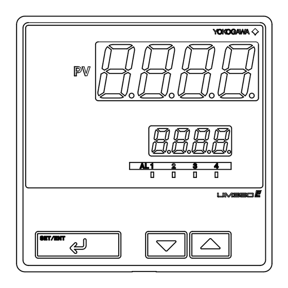
Display Specifications
• PV display:
4-digit, 7-segment red LED display, character height of
20 mm
Tightening torque
• Setpoint display: 4-digit, 7-segment, red LEDs, character height
of 9.3 mm
0.8 N·m or less
• Status indicating lamps: LEDs
3 . 7 m m
Safety and EMC Standards
• Safety: Complies with IEC/EN61010-1 (CE), approved by
C22.2 No.61010-1, approved by UL508.
or
Installation category : CAT. II Pollution degree : 2 (IEC/
EN61010-1, C22.2 No.61010-1)
Measurement category : I (CAT. I : IEC/EN61010-1)
Rated measurement input voltage : 10V DC max.(across
terminals), 300V AC max.(across ground)
Rated transient overvoltage : 1500V (Note)
Sales Unit
Note : It is a value on the safety standard which is assumed
by IEC/EN61010-1 in Measurement category I, and is not
the value which guarantees an apparatus performance.
CAUTION
This equipment has Measurement category I, there-
fore do not use the equipment for measurements
within Measurement categories II, III and IV.
Measurement category
1
CAT.1
2
CAT.2
Fold the cover in the direction
of the arrow.
3
CAT.3
Figure A
4
CAT.4
Fit the cover hold
over the protrusion
on the mounting bracket.
Entrance
Cable
• EMC standards: Complies with EN61326, EN61000-3-2,
EN61000-3-3 and EN55011 (CE).
Class A Group 1.
The instrument continues to operate at a measuring accuracy of
Figure B
within 20% of the range during tests.
Construction, Installation, and Wiring
11
-
12
-
13
)
• Construction: Only the front panel is dust-proof and drip-proof
(protection class IP55)
For side-by-side close installation the indicator loses its
dust-proof and drip-proof protection.
• Material: ABS resin and polycarbonate
• Case color: Black
• Weight: About 1 kg or less
• Dimensions:
UM350
96 (W)
96 (H)
100 (depth from panel face)
mm
UM330
96(W)
48 (H)
100 (depth from panel face)
mm
• Installation: Panel-mounting type. With top and bottom (or right
and left) mounting hardware (1 each)
or less for
• Panel cutout dimensions:
+0.8
+0.8
UM350
92
(W)
92
(H) mm
0
0
UM330
92
+0.6
(W)
45
+0.8
(H) mm
0
0
• Installation position: Up to 30° upward facing
(not designed for facing downward)
• Wiring: M3.5 screw terminals (for signal wiring and power/
ground wiring as well)
Power Supply Specifications
0.1 C /10
• Power supply: Rated voltage of 100 to 240 V AC ( 10%), 50/60 Hz
10 V DC for thermocouple, mV, or
• Power consumption: Max. 20 VA (8.0 W max.)
• Internal fuse rating: 250 V AC, 1.6A time-lug fuse
• Data backup: Non-volatile memory (can be written to up to
100,000 times)
• Withstanding voltage
1.0 C (15 to 35 C)
- Between primary terminals* and secondary terminals**:
At least 1500 V AC for 1 minute
- Between primary terminals* and grounding terminal:
At least 1500 V AC for 1 minute
- Between grounding terminal and secondary terminals**:
At least 1500 V AC for 1 minute
- Between secondary terminals**:
At least 500 V AC for 1 minute
-
; 24 V DC: terminals
-
)
14
15
21
22
* Primary terminals indicate power terminals and relay
output terminals
** Secondary terminals indicate analog I/O signal, and
contact input terminals
• Insulation resistance: 20 M or more at 500 V DC between
power terminals and grounding terminal
• Grounding: Class D grounding (grounding resistance of 100
or less)
Signal Isolations
• PV input terminals: Isolated from other input/output terminals.
Not isolated from internal circuit.
16
-
17
.
• 15 V DC loop power supply terminals: Not isolated from 4-20
16
-
17
)
mA analog output. Isolated from other input/output
terminals and internal circuit.
or less
• 24 V DC loop power supply terminals: Isolated from 4-20 mA
0.3% of span under standard operating
analog output terminals, other input/output terminals and
2 C, 55
10% RH, power frequency of
internal circuit.
• 4-20 mA analog output terminals (for retransmission): Not
isolated from 15 V DC loop power supply. Isolated from
other input/output terminals and internal circuit.
• Contact input terminals: Not isolated from communication
terminals. Isolated from other input/output terminals and
internal circuit.
• Relay contact output terminals: Not isolated between relay
contact output terminals. Isolated from other input/output
terminals and internal circuit.
• RS-485 communication terminals: Not isolated from contact
input terminals. Isolated from other input/output terminals
and internal circuit.
• Power terminals: Isolated from other input/output terminals and
internal circuit.
• Grounding terminals: Isolated from other input/output terminals
and internal circuit.
Environmental Conditions
• Normal operating conditions:
Ambient temperature: 0 to 50 C (40 C or less for side-by-side
close installation)
0 to 40 C if the 24V DC loop power supply of Model
UM330 is used
Temperature change rate: 10 C/h or less
Ambient humidity: 20 to 90% RH (no condensation allowed)
Magnetic field: 400 A/m or less
Continuous vibration at 5 to 14 Hz: Full amplitude of 1.2 mm or
less
Continuous vibration at 14 to 150 Hz: 4.9 m/s
2
or less
2
Short-period vibration: 14.7 m/s
, 15 seconds or less
Shock: 147 m/s
2
or less, 11 ms
Installation height: Height above sea level of 2000 m or less
Warm-up time: 30 minutes or more after power on
• Transportation and storage conditions:
Temperature: -25 to 70 C
Temperature change rate: 20 C/h or less
Humidity: 5 to 95% RH (no condensation allowed)
• Effects of changes in operating conditions
- Effects from changes in ambient temperature:
- On voltage or thermocouple input,
1 V/ C or
0.01%
of F.S./ C, whichever is larger
- On RTD input,
0.05 C / C (ambient temperature) or less
- On analog output,
0.05% of F.S./ C or less
- Effects from power supply fluctuation (within rated voltage
range)
- On analog input,
1 V/10 V or
0.01% of F.S. /10 V,
whichever is larger
- On analog output,
0.05% of F.S./ 10 V or less
Description
Remarks
For measurements performed
on circuits not directly
connected to MAINS.
For measurements performed
Appliances, portable
on circuits directly connected
equipments, etc.
to the low voltage installation.
For measurements performed
Distribution board,
in the building installation.
circuit breaker, etc.
For measurements performed
Overhead wire, cable
at the source of the low-voltage
systems, etc.
installation.
Internal Wiring
2
3
T
4
1
Outlet
IM 05F01D02-01E (1)
Advertisement
Table of Contents

Subscribe to Our Youtube Channel
Related Manuals for YOKOGAWA UM350


Summary of Contents for YOKOGAWA UM350
- Page 1 • Normal operating conditions: Make sure that all of the precautions are strictly adhered to. Yokogawa Electric Corporation assumes no liability for any • Relay contact rating for Alarm 1 to 3: 240 V AC, 1 A, or 30 V Power supply, grounding, relay contact outputs 600 V PVC insulated wires, JIS C 3307, 0.9 to 2.0 mm...
- Page 2 6. Terminal Wiring Diagrams NOTE Do not use unassigned terminals as relay terminals. UM350 Standard Type (Model UM350- PV input * Not configured at factory before shipment Receiving 4-20 mA DC Current * Wiring can only be carried out * Wiring can only be carried out Initial Settings User’s Manual...
- Page 3 SET/ENT Press the SET/ENT key once to display the parameter The following explanation of operation for the UM350’s panel, shown in the figure, is the same as that of the UM330’s “FUNC”. “RL” (minimum value of PV input range). panel.
- Page 4 2. Troubleshooting User’s Models UM350 / UM330 Troubleshooting Flow Digital Indicator with Alarms Manual If the operating display does not appear after turning on the indicator's power, try to solve the problem by following the User’s Manual procedure below. If the problem seems to be complex, contact the vendor from which you purchased the instrument.
- Page 5 Minimum value of Alarm-4 delay timer retransmission output scale UM350- 2, UM330- 1, UM330- 2. Alarm-4 setpoint Displayed only for UM350- 1, UM350- 2, UM330- 1, UM330- 2 DI function selection Protocol selection Description of Operating Parameter Setting Display PV peak value...
- Page 6 2. Lists of Parameters List of Alarm Types * Parameters relating to PV should all be set in real numbers. * The “User Setting” column in the table below is provided for the customer to record setpoints. For example, use temperature values to define alarm setpoints for The table below shows the alarm types and alarm actions.
Need help?
Do you have a question about the UM350 and is the answer not in the manual?
Questions and answers