
Subscribe to Our Youtube Channel
Related Manuals for YOKOGAWA MLX


Summary of Contents for YOKOGAWA MLX
-
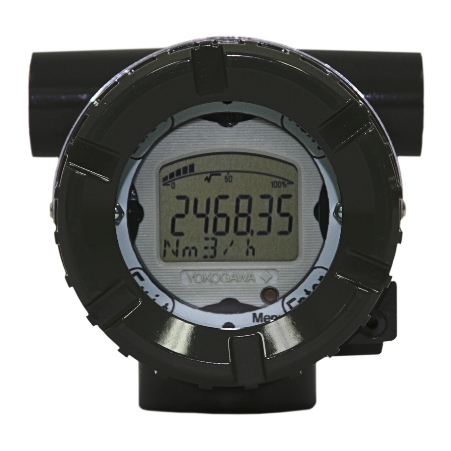
Page 1: Loop Powered Process Indicator
User’s Model MLX Loop Powered Process Indicator Manual IM 60A02S01-01E-A IM 60A02S01-01E-A Edition... -
Page 2: Table Of Contents
Page 2 of 51 Contents Loop Powered Process Indicator ..................1 Contents ............................2 1. Introduction ..........................3 1.1 Safe Use of This Product ....................4 1.2 Warranty ..........................5 1.3 ATEX Documentation ......................6 2. Handling Cautions ........................8 2.1 Model and Specifications Check .................. -
Page 3: Introduction
• • If the customer or any third party is harmed by the use of this product, Yokogawa assumes no responsibility for any such harm owing to any defects in the product which were not predictable, or for any indirect damages. -
Page 4: Safe Use Of This Product
If these instructions are not heeded, the protection provided by this instrument may be impaired. In this case, Yokogawa cannot guarantee that the instrument can be safely operated. Please pay special attention to the... -
Page 5: Warranty
− Use of the product in question in a location not conforming to the standards specified by Yokogawa, or due to improper maintenance of the installation location. − Failure or damage due to modification or repair by any party except Yokogawa or an approved representative of Yokogawa. -
Page 6: Atex Documentation
Francês. Se necessitar de instruções na sua lingual relacionadas com produtos Ex, deverá entrar em contacto com a delegação mais próxima ou com um representante da Yokogawa. Tous les manuels d’instruction des produits ATEX Ex sont disponibles en langue anglaise, allemande et française. - Page 7 Alle Betriebsanleitungen für ATEX Ex bezogene Produkte stehen in den Sprachen Englisch, Deutsch und Französisch zur Verfügung. Sollten Sie die Betriebsanleitungen für Ex-Produkte in Ihrer Landessprache benötigen, setzen Sie sich bitte mit Ihrem örtlichen Yokogawa-Vertreter in Verbindung. Alla instruktionsböcker för ATEX Ex (explosionssäkra) produkter är tillgängliga på engelska, tyska och franska.
-
Page 8: Handling Cautions
This chapter provides important information on how to handle the MLX Loop Powered Process Indicator. Read this carefully before using the indicator. The MLX indicator is thoroughly tested at the factory before shipment. When taking delivery of an instrument, visually check it to make sure that no damage occurred during shipment. -
Page 9: Model And Specifications Check
(b) When storing the indicator, repack it carefully in the packaging that it was originally shipped with. 2.4 Selecting the Installation Location (1) The MLX is designed to withstand severe environmental conditions. However, to ensure that it will provide years of stable and accurate performance, take the following precautions when selecting the installation location. -
Page 10: Insulation Resistance And Dielectric Strength Test
(6) Shock and Vibration (7) Although the MLX is designed to be relatively resistant to shock and vibration, an installation site should be selected where this is kept to a minimum. 2.5 Insulation Resistance and Dielectric Strength Test Since the MLX has undergone insulation resistance and dielectric strength tests at the factory before shipment, normally these tests are not required. -
Page 11: Installation Of An Explosion-Protected Instrument
2.6.1 Factory Mutual (FM) Certification 1) Technical Data a. FM Explosionproof/Dust-Ignition-Proof Type Caution for FM Explosionproof/Dust-Ignition-Proof type. Note 1. Model MLX Loop Process Indicators with optional code /FF1 applicable for use in potentially hazardous locations: Certificate No. 4000798 • Conforms to: FM 3600, FM 3615, FM 3616, UL 1203 •... - Page 12 Note 5. Special Conditions for Safe Use • In the case where the enclosure of the MLX is made of aluminum, if it is mounted in an area requiring Class 1 Division 1 equipment, it must be installed such, that, in the event of rare incidents or rare malfunction, ignition sources due to impact and friction sparks are excluded.
- Page 13 Page 13 of 51 Certificate No. 4000798 • • Conforms to: FM 3600, FM 3610, FMRC 3611, FM 3615, FM 3616, UL 913, UL 1203, UL 60079-0, UL 60079-11 • Explosionproof/Dust-Ignition-Proof for: - Class I, II, III; Groups A -G; Divisions 1 & 2. - Class I, Zone 1, Group IIC T4.
- Page 14 Mutual Explosionproof Approval. Note 6. Special Conditions for Safe Use • In the case where the enclosure of the MLX is made of aluminum, it must be installed such, that, even in the event of rare incidents, ignition sources due to impact and friction sparks are excluded.
- Page 15 Page 15 of 51 [Intrinsically safe] Group IIC, Zone 0 Class I, II, III, Division1 & 2 Groups A - G MLX Loop Indicator General 2- Wire Purpose Transmitter Safety Barrier Equipment 4-20mA Hazardous Area Non-Hazardous Area [Non-incendive] Group IIC, Zone 2 T4...
-
Page 16: Cenelec Atex Certification
CENELEC ATEX Non-Incendive Type Caution for CENELEC ATEX Intrinsically Safe/CENELEC ATEX Flameproof/ CENELEC ATEX Non-Incendive Type. Note 1. Model MLX Loop Process Indicators with optional code /KU21 applicable for use in potentially hazardous locations: • Certificate No. ITS13ATEX27856X • Certificate No. ITS13ATEX17857X •... - Page 17 Note 6. Special Conditions for Safe Use • In the case where the enclosure of the MLX is made of aluminum, if it is mounted in an area requiring Category 1 G equipment (EPL Ga), it must be installed such, that, in the event of rare incidents or rare malfunction, ignition sources due to impact and friction sparks are excluded.
- Page 18 Page 18 of 51 [Intrinsically safe] Group IIC, Zone 0 MLX Loop Indicator General 2- Wire Purpose Transmitter Safety Barrier Equipment 4-20mA Hazardous Area Non-Hazardous Area [Non-incendive] Group IIC, Zone 2 MLX Loop Indicator 2- Wire [Ex ic] Certified Transmitter...
- Page 19 Intrinsically Safe Certification. Note 5. Special Conditions for Safe Use In the case where the enclosure of the MLX is made of aluminum, if it is mounted • in an area requiring Category 1 G equipment (EPL Ga), it must be installed such, that, in the event of rare incidents or rare malfunction, ignition sources due to impact and friction sparks are excluded.
- Page 20 Page 20 of 51 Intrinsically Safe (Securite Intrinseque) for Class I II, III; Groups A - G; M1275DV Divisions 1 & 2; Zone 20, Class I, Zone 0, AEx ia IIC T4 Ga -40°C < Ta < +80°C Ui = 28V, Ii = 115mA, Pi = 0.65W, Ci = 0uF, Li = 0mH Explosionproof/Dust-Ignition-Proof for Class I, II, III;...
- Page 21 Page 21 of 51 3) Electrical connection The type of electrical connection is stamped near the electrical connection port according to the following marking. Thread Size Marking ISO M20 x 1.5 female ANSI ½ x 14 NPT female ISO G1/2 x 14 female Notes : Certification Conditions for Safe Use 1.
-
Page 22: Canadian Standards Association (Csa) Certification
1) Technical Data a. CSA Intrinsically Safe/CSA Explosionproof/ CSA Non-Incendive Type. Caution for CSA Intrinsically Safe/CSA Explosionproof/CSA Non-Incendive type. Note 1. Model MLX Loop Process Indicator with optional code /CU1 are applicable for use in potentially hazardous locations. Certificate No. 4000798 •... - Page 23 Note 6. Special Conditions for Safe Use • In the case where the enclosure of the MLX is made of aluminum, if it is mounted in an area requiring Class 1 Division 1 equipment, it must be installed such, that, in the...
- Page 24 MINIMIZE THE RISK FROM ELECTROSTATIC DISCHARGE OF PAINTED OR COATED PARTS OF EQUIPMENT. [Intrinsically safe] Group IIC, Zone 0 T4 Class I, II, III, Division1 & 2 Groups A - G MLX Loop Indicator General 2- Wire Purpose Transmitter Safety Barrier...
-
Page 25: Iecex Certification
IECEx Intrinsically Safe/IECEx Flameproof/ IECEx Non-Incendive Type Caution for IECEx Intrinsically Safe/ IECEx Flameproof/ IECEx Non-Incendive Type. Note 1. Model MLX Loop Process Indicator with optional code /SU2 are applicable for use in potentially hazardous locations. • Certificate No. IECEx ETL 13.0028X •... - Page 26 Note 6. Special Conditions for Safe Use • In the case where the enclosure of the MLX is made of aluminum, if it is mounted in an area requiring Category 1 G equipment (EPL Ga), it must be installed such, that, in the event of rare incidents or rare malfunction, ignition sources due to impact and friction sparks are excluded.
- Page 27 OF THE ENCLOSURE, SUCH AS RUBBING WITH A DRY CLOTH ON ANY SURFACE OF THE PRODUCT. PRECAUTIONS SHALL BE TAKEN TO MINIMIZE THE RISK FROM ELECTROSTATIC DISCHARGE OF PAINTED OR COATED PARTS OF EQUIPMENT [Intrinsically safe] Group IIC, Zone 0 MLX Loop Indicator General 2- Wire IECEx Certified Purpose...
- Page 28 Page 28 of 51 [Non-incendive] Group IIC, Zone 2 MLX Loop Indicator 2- Wire IECEx Certified Transmitter Equipment (non-incendive) 4-20mA Hazardous Area Non-Hazardous Area IM 60A02S01-01E-A...
-
Page 29: Emc Conformity Standards
EN61326-1 Class A, Table 2 (for use in industrial locations) NOTE YOKOGAWA recommends using metal conduit or twisted pair shielded cable for signal wiring to conform to the requirements of EMC regulations when installing the MLX in the plant. 2.8 Low Voltage Directive... -
Page 30: Installation
Page 30 of 51 3. Installation The MLX can be mounted on a wall or a 2” pipe. The housing is NEMA 4X/IP66/IP67 rated so it can be mounted outside in the field. "0 Ring" seals MUST be carefully examined after opening to ensure that the NEMA 4X/IP66/IP67 protection is maintained. -
Page 31: Mounting Examples
Page 31 of 51 3.1 Mounting Examples Figure 3.1 Mounting configurations IM 60A02S01-01E-A... -
Page 32: Wiring
(and, in certain countries, legal regulations) in order to preserve the effectiveness of their explosion-protected features. The MLX is powered by the current output loop and does not require external power. All devices must be wired in series with the current loop. Twisted pair shielded cable is recommended. -
Page 33: Wiring
Page 33 of 51 4.3 Wiring 4.3.1 Loop Configuration The following is a typical wiring example of the MLX connected to an EJA Pressure Transmitter. (1) General-use Type (Note: The EJA Transmitter below can be replaced with any 4-20mA 2 wire device. ) - Page 34 Page 34 of 51 (2) HART Type (Note: The HART Transmitter below can be replaced with any HART 4-20mA 2 wire device. ) MLX Loop Indicator HART Transmitter R Load J1 J2 Loop Power Supply Shorting Bar installed SUPPLY CHECK Figure 4.2 HART Type wiring example...
-
Page 35: Operation
5. Operation 5.1 Overview The MLX is loop powered. Connect it in series with a 4-20mA loop as per Section 4 “Wiring”. Observe correct polarity as the indicator is protected against reversed connections but will not display a reading. After properly connecting the indicator to a transmitter or other 4-20mA source, the display will indicate the value of the current flowing in the loop (0-100% for the standard model or other specified engineering units can be user defined). - Page 36 Page 36 of 51 Listing 1. MLX Menu Tree (Calibrate) (Set Units) (Common) 1. Start Cal 1. Common 1. % (Setup) 2. Return 2. Alphabetical 2. bar 3. Clear Units 3. barg 1. Calibrate 4. Return 4. degC 2. Eng units 5.
- Page 37 Page 37 of 51 MLX Menu Tree (cont.) (Bar) 1. Bar on From Indicators 2. Bar off 3. Return (x10) 1. x10 on 2. x10 off 3. Return (x100) 1. x100 on 2. x100 off 3. Return (x1000) 1. x1000 on 2.
- Page 38 Page 38 of 51 Listing 2. Alphabetic units List of alphabetical engineering units (from Alphabetical) BRIX GW.h BTU/SCF kg/cm2 %CH4 kg/cm2abs HL/H kg/cm2G %CO2 cal/kWh foot kg/d CC/MIN foot/p hPaabs kg/h foot/s hPaG kg/l %H2O CelD.P. footAq kg/m2 %LEL cf/d footAqabs kg/m2G cf/h...
- Page 39 Page 39 of 51 mgal/h mmol/l km3/d m/s2 Mgal/min mmP-P nGy/h km3/h mgal/min MMSCFD Nkm3/d km3/min Mgal/s mmWC Nkm3/h km3/s m3/d mgal/s mmWCabs Nl/h km3N/h m3/h Mgal_p mmWG Nl/min KMHO m3/min mgal_p mmWGabs Nl/s m3/p mGy/h Nm3/d kN.m m3/s mH2O Nm3/h kN/m2 m3N/h...
- Page 40 Page 40 of 51 Sm3/h ubbl_b/s ubbl_o/d uW/cm2 Sv/h ubbl_o/h ubbl_o/min ubbl_o/p ubbl_o/s vol% t/min vol%O2 volpct ug/l ug/m3 uGy/h W/m2 Torr UMHO wtpct TR/min UMHO/CM wtpctS umP-P wtppb ubbl/d uOhm wtppm ubbl/h X10L ubbl/min ubbl/s ubbl_b/d uS/cm ubbl_b/h uS/m ubbl_b/min USI/CM ubbl_b/p...
-
Page 41: Setting Engineering Units
For example, the factory default setting of the MLX is 0 – 100% with 2 decimal places. If a new full scale value of 100000 is desired and the number of decimal places is not set to 0, the maximum value that can be set is 9999.99. - Page 42 The numeric display shows the current engineering unit zero value with the least significant digit blinking. At this point, the menu buttons are redefined as in Table 5.2. Table 5.2 MLX key functions (when in Engineering units mode) Function Selects the digit to modify (digits advance from least significant to most significant to the sign symbol and back to least significant –...
-
Page 43: Maintenance
6.2 Calibration Instruments Selection Table 6.1 lists the instruments that can be used to calibrate the MLX. When selecting an instrument, consider the required accuracy level. Exercise care when handling these instruments to ensure they maintain the specified accuracy. -
Page 44: Rotating Display Direction
“Menu” button. 6.4 Rotating Display Direction The MLX display is designed so that it can be rotated in increments of 90 degrees. When there is a need to change the orientation of the display, use the following procedure: (1) Remove power from the MLX. -
Page 45: General Specifications
Page 45 of 51 7. General Specifications 7.1 Standard Specifications □FUNCTIONAL SPECIFICATIONS Input: 4-20mA DC 2-wire Voltage Drop: 3.5V at 20mA LCD Display Numerical: Six 7-segment digits Alpha-numerical: Six 14-segment characters Bar graph: 20-segment Bar graph. Symbols: P, SP, T, F, %, √, x10, x100, x1000 Configuration: User configurable for desired engineering units. - Page 46 (calibration, span, zero and engineering units). Root extraction For applications where the process variable is non-linear and based on the square root, 3/2 root or 5/2 root, the MLX can be configured to display the root function of the input.
-
Page 47: Model And Suffix Codes
Page 47 of 51 7.2 Model and Suffix Codes MODEL AND SUFFIX CODES Model Suffix Codes Description ………………………………..Loop Indicator Input signal -A…………………………………... 4 to 20mA DC 1………………………….... 2 inch Horizontal Pipe Mounting 2………………………….... 2 inch Vertical Pipe (or wall mount) 1………………………….. - Page 48 Page 48 of 51 OPTIONAL SPECIFICATIONS (For Explosion Protected Type) Item Description Code CSA Intrinsically Safe/CSA Explosionproof/ CSA Dust-Ignition-Proof /CSA Non-incendive Approval Certified to: CSA C22.2 No. 25, CSA C22.2 No. 30, CSA C22.2 No. 157, CSA C22.2 No. 213, CSA C22.2 No.
- Page 49 OPTIONS Specify the following when ordering: 1. Model and suffix codes. The MLX is fully field configurable from the front panel. To order a 2. Option codes. pre-configured unit, specify the /ENG option followed by the desired 3. Tag number setpoints (zero, full scale, and engineering units).
-
Page 50: Dimensions
Page 50 of 51 7.5 Dimensions IM 60A02S01-01E-A... -
Page 51: Revision Record
Page 51 of 51 Revision Record Title: MLX Loop Powered Process Indicator Manual No.: IM 60A02S01-01E-A Edition Date Page Revised Item January 2012 New publication March 2012 14, 21 Removed J12 reference; modified Specifications July 2013 11-22 Added ATEX, CSA and IEC. Changed Section 5.
Need help?
Do you have a question about the MLX and is the answer not in the manual?
Questions and answers