
Related Manuals for YOKOGAWA UM33A


Summary of Contents for YOKOGAWA UM33A
- Page 1 User’s Manual UM33A Digital Indicator with Alarms User’s Manual IM 05P03D21-01EN IM 05P03D21-01EN 4th Edition...
- Page 2 Product Registration Thank you for purchasing YOKOGAWA products. YOKOGAWA provides registered users with a variety of information and services. Please allow us to serve you best by completing the product registration form accessible from our homepage. http://www.yokogawa.com/ns/reg/...
-
Page 4: Introduction
Introduction Thank you for purchasing the UM33A digital indicator with alarms (hereinafter referred to as UM33A). This manual describes how to use UM33A functions other than UM33A’s communication function and ladder sequence function. Please read through this user’s manual carefully before using the product. -
Page 5: Notice
Yokogawa Electric’s sales office or sales representative. ● Under no circumstances may the contents of this manual, in part or in whole, be transcribed or copied without our permission. Trademarks ● Our product names or brand names mentioned in this manual are the trademarks or registered trademarks of Yokogawa Electric Corporation (hereinafter referred to as YOKOGAWA). ● Microsoft, MS-DOS, Windows, Windows XP, Windows Vista, and Windows 7 are either registered trademarks or trademarks of Microsoft Corporation in the United States and/or other countries. - Page 6 • Be sure to use the spare parts approved by YOKOGAWA when replacing parts or consumables.
-
Page 7: Handling Precautions For The Main Unit
• YOKOGAWA makes no warranties regarding the product except those stated in the WARRANTY that is provided separately. • The product is provided on an “as is” basis. YOKOGAWA assumes no liability to any person or entity for any loss or damage, direct or indirect, arising from the use of the product or from any unpredictable defect of the product. -
Page 8: Checking The Contents Of The Package
The /LP option can be specified only when the code for Type 2 code is any of “0”, “1” or “2”, and the Type 3 code is “0”. When the /CT option is specified, the UM33A does not conform to the safety standards (UL and CSA) and CE marking (Products with /CT option are not intended for EEA-market). - Page 9 Coating Treatment (1) HumiSeal coating treatment Apply HumiSeal coating to the printed circuit board assembly. Do not apply HumiSeal coating to the following parts: connector, gold-plated contact area, relay part, RJC device, and in the vicinity of the push switch/LED lamp. (2) Apply terminal coating to the gold-plated contact area on the printed circuit board.
- Page 10 Resistance Module *: Necessary to input the current signal to the voltage input terminal. • Terminal cover For UM33A, Model: UTAP002 • Brackets Part number L4502TP (2 pieces for fixing the right and left parts) • User’s Manual (A4 size) * User’s Manual can be downloaded from a website.
-
Page 11: Symbols Used In This Manual
Symbols Used in This Manual This symbol is used on the instrument. It indicates the possibility of injury to the user or damage to the instrument, and signifies that the user must refer to the user’s manual for special instructions. The same symbol is used in the user’s manual on pages that the user needs to refer to, together with the term “WARNING” or “CAUTION.” WARNING Calls attention to actions or conditions that could cause serious or fatal injury to the user, and indicates precautions that should be taken to prevent such occurrences. -
Page 12: How To Use This Manual
Chapters 1 to 17 as shown below. Chapter Title and Description Introduction to Functions Describes the main functions of the UM33A. UM33A Operating Procedures Describes the flow from unpacking to regular operations. Part Names Describes part names and functions on the front panel. - Page 13 Blank Page...
-
Page 14: Table Of Contents
Safety Precautions ....................... ii Handling Precautions for the Main Unit ................iv Checking the Contents of the Package ................v Model and Suffix Codes of UM33A..................v Symbols Used in This Manual ................... viii How to Use This Manual ..................... ix Chapter 1 Introduction to Functions Quick Setting Function ..................... - Page 15 Contents (3) Setting 10-segment Linearizer ..................7-8 Setting Input Sampling Period ..................7-10 Chapter 8 Functions Function Block Diagrams ....................8-1 Chapter 9 Alarm Functions Setting Alarm Type ......................9-1 Setting Number of Alarm Groups to Use ................9-7 Setting Hysteresis to Alarm Operation ................9-8 Delaying Alarm Output (Alarm Delay Timer) ..............
- Page 16 Contents Chapter 13 Parameter Initialization 13.1 Initializing Parameter Settings to Factory Default Values ..........13-1 13.2 Registering and Initializing User Default Values ............. 13-2 13.2.1 Registering as User Setting (Default) Values............ 13-2 13.2.2 Initializing to User Setting (Default) Values ............13-2 Chapter 14 Power Failure Recovery Processing / Power Frequency Setting / Other Settings 14.1...
- Page 17 Blank Page...
-
Page 18: Chapter 1 Introduction To Functions
Chapter 1 Introduction to Functions 1.1 Quick Setting Function The Quick setting function is a function to easily set the basic function of the indicator. Check the contents. Buy and Unpacking Installation and Wiring: Chapter 16 Installation Install and wire a indicator, and then turn on and Wiring the power. -
Page 19: Input/Output Function
External device such as recorder etc. UM33A Current Contact Input Two contact inputs are incorporated in UM33A. The PV peak value and PV bottom value can be reset, and the alarm latch can be released. ► Chapter 11 Contact Input/Output Functions Contact Output Up to 9 contact outputs can be incorporated. - Page 20 1.2 Input/Output Function 24 V DC Loop Power Supply (optional suffix code: /LP) 24 V DC loop power supply can be supplied to 2-wire transmitter. ► 16.4.7 24 V DC Loop Power Supply Wiring UM33A 2-wire transmitter IM 05P03D21-01EN...
-
Page 21: Display And Key Functions
To intended use of the operator, the display level of the parameter can be set. ► Chapter 17 Parameters User Function Keys The UM33A has a user function key (Fn). Assign a function to a user function key to use it as an exclusive key. ► 12.2 Assigning Function to User Function Key... -
Page 22: Communication Functions
Up to 31 connected slaves with a maximum length of 1200m CC-Link Communication The UM33A can be used as the slave devices for CC-Link communication. Read-out of PV, operation or alarm status, and SP setting can be done by accessing the remote I/O on the master unit of CC-Link. - Page 23 Maintenance Port Communication (Power supply is not required for the UM33A) Maintenance port is used to connect with the dedicated cable when using LL50A Parameter Setting Software (sold separately). The parameters can be set without supplying power to the UM33A. LL50A Parameter Setting Software To USB terminal Dedicated cable CAUTION When using the maintenance port, do not supply power to the indicator.
-
Page 24: Definition Of Main Symbols And Terms
1.5 Definition of Main Symbols and Terms Main Symbol PV: Measured input value A1 to A8: Alarm setpoint PEAK: PV peak value BOTM: PV bottom values ► 16.4 Wiring Engineering Units Input range (scale): the PV range low limit is set to 0%, and the high limit is set to 100% for conversion. - Page 25 Blank Page...
-
Page 26: Chapter 2 Um33A Operating Procedures
Chapter 2 UM33A Operating Procedures UM33A Operating Procedures Installation Install and wire a indicator. and Wiring Installation and Wiring: Chapter 16 Power ON Intput setup Intput setup Section 7.1 Quick setting function: Chapter 5 Set the other parameters as necessary. - Page 27 Blank Page...
-
Page 28: Chapter 3 Part Names
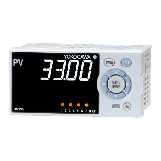
Chapter 3 Part Names 3.1 Names and Functions of Display Parts UM33A (1) PV display (3) Symbol display (4) Data display (2) Group display (6) Key navigation indicator (5) Event indicator (7) Parameter display level (8) Security indicator indicator (2) + (3) + (4) : Setpoint display No. in figure... -
Page 29: Names And Functions Of Keys
It is the communication interface to the adapter cable Light-loader interface when setting and storing parameters via PC. The LL50A Parameter Setting Software (sold separately) is required. The UM33A has Fn key. User function keys The user can assign a function to the key. The function is set by the parameter. - Page 30 Maintenance Port (Power supply is not required for the UM33A). The maintenance port is used to connect with the dedicated cable when using LL50A Parameter Setting Software (sold separately). The parameters can be set without supplying power to the UM33A. Maintenance port CAUTION When using the maintenance port, do not supply power to the indicator. Otherwise, the indicator does not work normally.
-
Page 31: List Of Display Symbols
3.3 List of Display Symbols The following shows the parameter symbols, menu symbols, alphanumeric of guide, and symbols which are displayed on the UM33A. Figure (common to all display area) PV display (14 segments): Alphabet Symbol display and Data display (11 segments): Alphabet (lower-case) IM 05P03D21-01EN... - Page 32 3.3 List of Display Symbols PV display (14 segments): Symbol Space ‘ IM 05P03D21-01EN...
-
Page 33: Brief Description Of Setting Details (Parameters)
Brief Description of Setting Details (Parameters) This manual describes the Setting Details as follows in addition to the functional Description. Setting Details (Display Example) Parameter Display Name Setting range Menu symbol symbol level Set a display value of setpoint of PV alarm, or velocity alarm. Alarm-1 to -8 -19999 to 30000 (Set a value A1 to A8 EASY setpoint... -
Page 34: Chapter 4 Basic Operation
Chapter 4 Basic Operation Overview of Display Switch and Operation Keys The following shows the transition of Operation Display, Operation Parameter Setting Display, and Setup Parameter Setting Display. The “Operation Parameter Setting Display” has the parameters for setting the functions necessary for the operation. The “Setup Parameter Setting Display” has the parameters for setting the basic functions of the indicator. - Page 35 4.1 Overview of Display Switch and Operation Keys The display pattern of the UM33A is as follows; the Menu Display and Parameter Setting Display. For the Operation Display, see Chapter 6, “Monitoring of Regular Operations.” Display Description The Menu Display is segmented by the function. The scrolling guide for the menu is displayed on PV display. The guide display can be turned on/off with the Fn key.
- Page 36 4.1 Overview of Display Switch and Operation Keys Display Shown at the End (the Lowest Level) of the Parameter Setting Display As shown in the figure below, the END Display is shown to indicate the end of the Menu Display and Parameter Setting Display. There are no setting items. The scrolling guide of END is displayed. END is displayed. Basic Key Operation Sequence ● To move to the Setup Parameter Setting Display Hold down the PARA key and the Left arrow key simultaneously for 3 seconds.
-
Page 37: How To Set Parameters
4.2 How to Set Parameters The following operating procedure describes an example of setting alarm setpoint (A2). Operation Hold down the PARA key for 3 seconds in the Operation Display to call up the [AL] Menu Display. Press the SET/ENTER key to display the [A1] Parameter Setting Display. Press the Down arrow key to display the [A2] Parameter Setting Display. - Page 38 4.2 How to Set Parameters Press the SET/ENTER key to register the setpoint (the setpoint stops blinking). Press the SET/ENTER key to register the setpoint (the setpoint stops blinking). Press the PARA key once to return to the Menu Display. Press the DISP key once to return to the Operation Display.
- Page 39 4.2 How to Set Parameters How to Set Parameter Setpoint Numeric Value Setting Display the Parameter Setting Display. Press the SET/ENTER key to move to the setting mode (the setpoint blinks). Press the Left arrow key to move one digit to the left. (Press the Right arrow key to move one digit to the right.) Press the Up or Down arrow key to change the setpoint.
- Page 40 4.2 How to Set Parameters Time (minute.second) Setting Example of 17 minutes 59 seconds Display the Parameter Setting Display. Press the SET/ENTER key to move to the setting mode (the setpoint blinks). Press the Left arrow key to move one digit to the left. (press the Right arrow key to move one digit to the right.) Press the Up or Down arrow key to change the setpoint.
- Page 41 Blank Page...
-
Page 42: Chapter 5 Quick Setting Function
Chapter 5 Quick Setting Function 5.1 Setting Using Quick Setting Function Description The Quick setting function is a function to easily set the basic function of the indicator. The Quick setting function starts when the power is turned on after wiring. The following lists the items to set using the Quick setting function. (1) Input function (PV input, range, scale (at voltage/current input), etc.) IM 05P03D21-01EN... - Page 43 5.1 Setting Using Quick Setting Function Flowchart of Quick Setting Function Power ON Decide whether or not to use the Quick setting function. Press the UP arrow key to select YES. Press the SET/ENTER key to start the Quick setting function. Press the Down arrow key to select NO. Press the SET/ENTER key not to start the Quick setting function.
- Page 44 5.1 Setting Using Quick Setting Function Setting Example Set the following parameters to set to thermocouple Type K (range: 0.0 to 500.0ºC). No need to change the parameters other than the following parameters. Set QSM = YES to enter the quick setting mode. (1) Set IN = K1. (2) Set UNIT = C (initial value).
- Page 45 5.1 Setting Using Quick Setting Function Setting Details Input Function Parameter Display Name Setting range Menu symbol symbol level OFF: Disable K1: -270.0 to 1370.0 ºC / -450.0 to 2500.0 ºF K2: -270.0 to 1000.0 ºC / -450.0 to 2300.0 ºF K3: -200.0 to 500.0 ºC / -200.0 to 1000.0 ºF J: -200.0 to 1200.0 ºC / -300.0 to 2300.0 ºF T1: -270.0 to 400.0 ºC / -450.0 to 750.0 ºF T2: 0.0 to 400.0 ºC / -200.0 to 750.0 ºF...
- Page 46 5.1 Setting Using Quick Setting Function Input Function (Continued) Parameter Display Name Setting range Menu symbol symbol level 0: No decimal place PV input scale 1: One decimal place decimal point EASY 2: Two decimal places position 3: Three decimal places 4: Four decimal places Maximum value of EASY PV input scale -19999 to 30000, (SL<SH),...
-
Page 47: Restarting Quick Setting Function
5.2 Restarting Quick Setting Function Once functions have been built using the Quick setting function, the Quick setting function does not start even when the power is turned on. The following methods can be used to restart the Quick setting function. ● Set the parameter QSM (Quick setting mode) to ON and turn on the power again. ● Set the parameter IN (PV input type) to OFF and turn on the power again. -
Page 48: Chapter 6 Monitoring Of Regular Operations App
Chapter 6 Monitoring of Regular Operations 6.1 Monitoring of Operation Displays 6.1.1 Operation Display Transitions ► Registration of SELECT Display: 12.1.3 Registering SELECT Display (Up to 5 displays) SP Display (SP can be changed.) SELECT Displays 1 to 5 (Displayed only when SELECT Display is registered. (The figure on the left is the example of the parameter A1 (alarm-1 setpoint).) IM 05P03D21-01EN... - Page 49 6.1 Monitoring of Operation Displays Details of the Operation Display The following is the Operation Display types and each display and operation description. PV display Setpoint display Operation Display Display and operation description PV display: Displays measured input value (PV). PV Display (Setpoint display shows nothing.) SELECT Display is for registering frequently-used parameters from Parameter Setting Display, and for displaying them on Operation Display so that the parameter settings can be easily changed in normal operation.
-
Page 50: Setting Alarm Setpoint
6.2 Setting Alarm Setpoint Setting Display Operation Display > PARA key for 3 seconds (to Parameter Setting Display [AL] Menu Display) > SET/ENTER key (The setting parameter is displayed.) > Down arrow key (The setting parameter is displayed.) Setting Details Parameter Display Name Setting range Menu symbol symbol level... -
Page 51: Releasing On-State (Latch) Of Alarm Output
6.3 Releasing On-State (Latch) of Alarm Output Description Alarm latch can be released by any of the following. (1) User function key (2) Communication (3) Contact input For the switching operation by using the above, the last switching operation is performed. Releasing the alarm latch function releases all of the latched alarm outputs. By factory default, the function is not assigned to the user function key. -
Page 52: Confirmation Of Pv Peak And Bottom Value
6.4 Confirmation of PV peak and bottom value Description Displays the maximum value and minimum value of PV input during operation. This parameter is not to be set. Setting Details Parameter Display Name Setting range Menu symbol symbol level Display only PEAK PV peak value EASY -100.0 to 100.0% of PV input BOTM PV bottom value EASY... - Page 53 Blank Page...
-
Page 54: Chapter 7 Input (Pv) Functions
Chapter 7 Input (PV) Functions 7.1 Setting Functions of PV Input 7.1.1 Setting Input Type, Unit, Range, Scale, and Decimal Point Position Description The figure below describes the case of PV input. Example of Temperature Input The figure below is an example of setting Type K thermocouple and a measurement range of 0.0 to 800.0 ºC. -270.0°C 1370.0°C Input type... - Page 55 7.1 Setting Functions of PV Input Setting Details Parameter Display Name Setting range Menu symbol symbol level OFF: Disable K1: -270.0 to 1370.0 ºC / -450.0 to 2500.0 ºF K2: -270.0 to 1000.0 ºC / -450.0 to 2300.0 ºF K3: -200.0 to 500.0 ºC / -200.0 to 1000.0 ºF J: -200.0 to 1200.0 ºC / -300.0 to 2300.0 ºF T1: -270.0 to 400.0 ºC / -450.0 to 750.0 ºF T2: 0.0 to 400.0 ºC / -200.0 to 750.0 ºF...
- Page 56 7.1 Setting Functions of PV Input (Continued) Parameter Display Name Setting range Menu symbol symbol level 0: No decimal place PV input scale decimal 1: One decimal place point position EASY 2: Two decimal places (Scaling) (for voltage / current 3: Three decimal places input) 4: Four decimal places Maximum value of PV input scale -19999 to 30000, (SL<SH),...
-
Page 57: Setting Burnout Detection For Input
7.1 Setting Functions of PV Input 7.1.2 Setting Burnout Detection for Input Description The input value when input burnout occurs can be determined. The input value is 105.0% of the input range when the upscale is set, and -5.0% of the input range when the downscale is set. Burnout detection is activated for TC, RTD, and standard signal (0.4–2 V, 1–5 V or 4-20 mA). -
Page 58: Setting Reference Junction Compensation (Rjc) Or External Reference Junction Compensation (Erjc)
RJC function of the indicator can be turned off. External Reference Junction Compensation (ERJC) For TC input, a temperature compensation value for external device can be set. The external RJC can be used only when RJC = OFF. UM33A Terminal block Compensating lead wire Furnace UM33A... -
Page 59: Correcting Input Value
7.1 Setting Functions of PV Input 7.1.4 Correcting Input Value (1) Setting Bias and Filter Description PV Input Bias The PV input bias allows bias to be summed with input to develop a measured value for display use inside the indicator. This function can also be used for fine adjustment to compensate for small inter- instrument differences in measurement reading that can occur even if all are within the specified instrument accuracies. -
Page 60: Setting Square Root Extraction And Low Signal Cutoff Point
7.1 Setting Functions of PV Input Setting Details Parameter Display Name Setting range Menu symbol symbol level -100.0 to 100.0% of PV PV input bias EASY input range span (EUS) PV input filter EASY OFF, 1 to 120 s Parameter Display Name Setting range Menu symbol symbol level -100.0 to 100.0% of each A.BS PV analog input bias input range span (EUS) -
Page 61: Setting 10-Segment Linearizer
7.1 Setting Functions of PV Input (3) Setting 10-segment Linearizer Description The 10-segment linearizer can be used for PV input and retransmission output. ► Function block diagram: 8.1 Function block diagram ► Output Linearizer: 10.2 Setting 10-segment Linearizer for Output 10-segment Linearizer Bias This function is used to correct an input signal affected by sensor deterioration. The corrected values are obtained by adding the corresponding bias values to each of the 11 points of optionally set input values. - Page 62 7.1 Setting Functions of PV Input Setting Details Parameter Name Display level Setting range Menu symbol symbol 10-segment -66.7 to 105.0% of input range A1 to A11 linearizer PYS1 (EU) input 10-segment linearizer bias: -66.7 to 105.0% of input range span 10-segment (EUS) B1 to B11 linearizer 10-segment linearizer output approximation: -66.7 to 105.0% of input range (EU)
-
Page 63: Setting Input Sampling Period
7.2 Setting Input Sampling Period Setting Details Parameter Display Name Setting range Menu symbol symbol level 50: 50 ms Input sampling period 100: 100 ms 200: 200 ms 7-10 IM 05P03D21-01EN... -
Page 64: Chapter 8 Functions
Chapter 8 Functions Function Block Diagrams Description The Function block diagram describes only the basic functions. Parameter symbols in the Function block diagram describe representative parameters. For the functions and parameters which are not described in Function block diagram, see the following. - Page 65 8.1 Function Block Diagrams Equipped as standard Equipped as standard. PV input Contact inputs RS-485 CC-Link Com. Com. Input type Input unit UNIT Input range/scale RH, RL SH, SL PV analog input bias A.BS Square root extraction A.LC A.SR PV analog input filter A.FL 10-seg.
-
Page 66: Chapter 9 Alarm Functions
Chapter 9 Alarm Functions 9.1 Setting Alarm Type Description The alarm-related parameters consist of the alarm type (type, stand-by action, energized/ de-energized, and latch function), PV velocity alarm time setpoint, alarm hysteresis, alarm (On-/Off-) delay timer, and alarm setpoint. Alarm-related parameter Number of settings Alarm type 8 (number of settings) PV velocity alarm time setpoint 8 (number of settings) - Page 67 9.1 Setting Alarm Type PV High Limit Alarm and PV Low Limit Alarm PV high limit alarm output PV high limit Alarm hysteresis alarm setpoint Alarm hysteresis PV low limit alarm setpoint PV low limit alarm output Time Contact type in the figure above: Energized when an event occurs (factory default). PV Velocity Alarm PV velocity alarm output...
- Page 68 9.1 Setting Alarm Type Fault diagnosis Alarm The function outputs an alarm signal in the following cases. The corresponding event (EV) lamp is lit and the contact output turns on (when the contact type is energized). • Burnout of PV input, RSP remote input, or auxiliary analog input •...
- Page 69 9.1 Setting Alarm Type Alarm Latch Function The alarm latch function is a function for keeping the alarm output (keeping the alarm output on) after entering the alarm condition (alarm output is turned on) until an order to release the alarm latch is received. The alarm latch function has the following four types of action.
- Page 70 9.1 Setting Alarm Type Release of Alarm Latch The alarm latch function can be cancelled by the user function key, via communication, or by contact input. Cancelling the alarm latch function cancels all latched alarm outputs. ► Release by user function key: 12.2 Assigning Function to User Function Key and A/M key ► Release by contact input: 11.1.1 Setting Contact Input Function ► Release via communication: UTAdvanced Series Communication Interface User’s Manual PV high limit alarm setpoint Alarm hysteresis Alarm hysteresis PV low limit...
- Page 71 9.1 Setting Alarm Type Setting Details Parameter Display Name Setting range Menu symbol symbol level AL1 to AL8 Alarm-1 to -8 type EASY See the table below. ALRM PV velocity alarm time 00.01 to 99.59 VT1 to VT8 EASY setpoint 1 to 8 (minute.second) Note1: The initial values of the parmeters AL1 to AL8 and VT1 to VT8 are "8". The number of alarms can be changed using the parameter ALNO.
-
Page 72: Setting Number Of Alarm Groups To Use
9.2 Setting Number of Alarm Groups to Use Description Up to eight alarm groups of alarm type, alarm hysteresis, alarm (On-/Off-) delay timer, and alarm setpoint are available. Unused alarm parameters can be hidden and their functions can be turned off. When ALNO. = 4, for example, only the four groups of alarm type, PV velocity alarm time setpoint, alarm hysteresis, alarm delay timer, and alarm setpoint are displayed. -
Page 73: Setting Hysteresis To Alarm Operation
9.3 Setting Hysteresis to Alarm Operation Description If the On/Off switch of the alarm output is too busy, you can alleviate the busyness by increasing the alarm hysteresis. Hysteresis for PV High Limit Alarm Point of ON/OFF action Output (alarm setpoint) Hysteresis When Setting Hysteresis of 5ºC and 15ºC for PV High Limit Alarm HYS: 5ºC (example) HYS: 15ºC (example) Closed (ON) Closed (ON) Open... -
Page 74: Delaying Alarm Output (Alarm Delay Timer)
9.4 Delaying Alarm Output (Alarm Delay Timer) Description The alarm on-delay timer is a function for turning on the alarm when the alarm condition occurs, and the timer starts and the set time elapses. The timer is reset if the alarm condition is removed while the timer is running. No alarm is generated. - Page 75 Blank Page...
-
Page 76: Chapter 10 Retransmission Output Functions
Chapter 10 Retransmission Output Functions 10.1 Setting Retransmission Output Terminal, Type, and Scales Description ► Current output range: 10.3 Changing Current Output Range Minimum value of Maximum value of PV input range PV input range 0.0°C 200.0°C PV scale 50.0°C Retransmission scale 150.0°C Output range 4 mA 20 mA (output signal) To Recorder Setting Details Parameter Display... -
Page 77: Setting 10-Segment Linearizer For Output
10.2 Setting 10-segment Linearizer for Output Description The 10-segment linearizer can be used for PV input and retransmission output. ► Function block diagram: 8.1 Function block diagram ► 10-segment linearizer input: 7.1.4 (3) Setting 10-segment Linearizer 10-segment Linearizer Biasing This function is used to correct the output by adding the corresponding bias values to each of the 11 points of optionally set input values. - Page 78 10.2 Setting 10-segment Linearizer for Output Setting Details Parameter Name Display level Setting range Menu symbol symbol 10-segment Output linearizer: -5.0 to A1 to A11 linearizer 105.0% input 10-segment Output linearizer: -5.0 to B1 to B11 linearizer 105.0% PYS2 output 0: 10-segment linearizer 10-segment bias linearizer 1: 10-segment linearizer mode approximation Note1: The group number 2 is displayed on Group display while each parameter is displayed.
-
Page 79: Changing Current Output Range
10.3 Changing Current Output Range Description The analog output type can be selected from among 4 to 20, 0 to 20, 20 to 4, or 20 to 0 Setting Details Parameter Display Name Setting range Menu symbol symbol level 4-20: 4 to 20 mA, RET current output 0-20: 0 to 20 mA, RET.A... -
Page 80: Setting Split Computation Output Function
10.4 Setting Split Computation Output Function Description The split computation output can be output by setting the breaking points for two points. The current output range can be changed. ► Current output range: 10.3 Changing Current Output Range Setting Example RET terminal Retransmission output type RTS=PV1 Current output 100% segmental point RET.H=75.0%... -
Page 81: Using 15 V Dc Loop Power Supply
10.5 Using 15 V DC Loop Power Supply Description The 15 V DC loop power supply is a function to supply DC power (14.5 to 18.0 V DC (21 mA DC)) to a 2-wire transmitter. The loop power supply block is isolated from the indicator’s internal circuitry. In addition, the block is equipped with a current limiting circuit. -
Page 82: Chapter 11 Contact Input/Output Functions
Chapter 11 Contact Input/Output Functions 11.1 Setting Contact Input Function 11.1.1 Setting Contact Input Function Description The contact input function works by setting the contact input number (I relay) to functions such as the operation mode. This explanation assumes that the contact type is energized. (The function is executed when the contact is turned on) PV peak and bottom values reset (RST) PV peak and bottom values can be released using contact input. - Page 83 PV peak and bottom values reset Latch release LCD backlight ON/OFF switch See the following PVRW PV red/white switch section, "UM33A DI.SL Message display interruption 1 DI and Setpoint". Message display interruption 2 Message display interruption 3 Message display interruption 4...
-
Page 84: Changing Contact Type Of Contact Input
11.1 Setting Contact Input Function 11.1.2 Changing Contact Type of Contact Input Description The contact type can set the action direction of contact input assigned to the function. Setting Details Contact Input Equipped as Standard Parameter Display Name Setting range Menu symbol symbol level 0: The assigned function is DI1.D DI1 contact type enabled when the contact input is closed. -
Page 85: Setting Contact Output Function
DO12 function selection DO3.S DO13 function selection See the following section. DO4.S DO14 function selection DO5.S DO15 function selection Refer to the table below for presence/absence of UM33A contact output. Suffix code: Type 2 Terminal area ALM4 (101-103) – E1-terminal area – –... - Page 86 11.2 Setting Contact Output Function Alarm Status The alarm status can be output to the contact output. (The setpoints below are I relay numbers.) ► I relay: UTAdvanced Series Communication Interface (RS-485, Ethernet) User's Manual Setpoint Function Alarm output Alarm status status 4321 4353 Alarm 1 4322 4354 Alarm 2 4323 4355 Alarm 3 4325 4357 Alarm 4...
- Page 87 11.2 Setting Contact Output Function Key and Display Status The key and display status can be output to the contact output. (The setpoints below are I relay numbers.) Contact status Setpoint Function 4705 PARA key 4706 DISP key 4707 Right arrow key 4708 Down arrow key Key is pressed Key is not pressed 4709 SET/ENTER key...
-
Page 88: Changing Contact Type Of Contact Output
1: When the event of assigned DO4.D DO14 contact type function occurs, the contact output is opened. DO5.D DO15 contact type Refer to the table below for presence/absence of UM33A contact output. Suffix code: Type 2 Terminal area ALM4 (101-103) – E1-terminal area –... - Page 89 Blank Page...
-
Page 90: Chapter 12 Display, Key, And Security Functions
Chapter 12 Display, Key, and Security Functions 12.1 Setting Display Functions 12.1.1 Setting Active Color PV Display Function The active color PV display function changes the PV display color when an event occurs. Description Link to Alarm The PV display color changes by linking to the alarm 1 or alarm 2. The following is an example of operation linking to alarm 1. Set the alarm-1 type to “PV high limit alarm”... - Page 91 12.1 Setting Display Functions Use in Fixed Color PV display color can be fixed in red. It can also be fixed in white. PV color: red A1 color: orange (A1 color cannot be changed.) Link to DI The PV display color changes by linking to DI (ON/OFF). The following is an example for changing the display color by a state of DI1.
-
Page 92: Masking Arbitrary Display Value In Operation Display
12.1 Setting Display Functions 12.1.2 Masking Arbitrary Display Value in Operation Display Description Display/non-display of the PV display, Setpoint display, and Status display in the Operation Display can be set. Items that you do not want to display can be set to non-display. For example, if PV display is set to non-display, the following items are not displayed: PV on the PV display, the scrolling guide in the Menu Display and Parameter Setting Display. -
Page 93: Registering Select Display (Up To 5 Displays)
12.1 Setting Display Functions 12.1.3 Registering SELECT Display (Up to 5 Displays) Description Registering frequently changed-operation parameters (except for the operation mode) in the SELECT Display of the Operation Displays will allow you to change parameter settings easily. A maximum of five Displays can be registered. Set the D register number of the parameter you wish to register for the registration to the SELECT Display. -
Page 94: Changing Event Display
12.1 Setting Display Functions 12.1.4 Changing Event Display Description The UM33A has four event (EV) lamps. The alarms 1 to 8 are assigned to EV1 to EV8. Setting Details Parameter Display Menu Name Setting range symbol level symbol Setting range: 4001 to 6304 OFF: Disable 4321: Link to alarm 1 (Lit when the alarm occurs) -
Page 95: Masking Least Significant Digit Of Pv Display
12.1 Setting Display Functions 12.1.5 Masking Least Significant Digit of PV Display Description With and without least significant digit of the PV in the Operation Display can be set. If the least significant digit is set to none, the value in the least significant can be truncated or rounded. The internal value is not changed depending on whether with or without least significant digit (the value is for display only). -
Page 96: Setting Economy Mode
12.1 Setting Display Functions 12.1.6 Setting Economy Mode Description The LCD backlight ON/OFF can be set in the following methods. Setting the LCD backlight to OFF saves energy. User Function Keys The LCD backlight ON/OFF switch can be assigned to the user function key. ► User function key: 12.2 Assigning Function to User Function Key Backlight OFF timer The backlight OFF timer sets the economy mode parameter to ON. -
Page 97: Setting Message Function
12.1 Setting Display Functions 12.1.8 Setting Message Function Description Using the message function and turning the contact input on/off, the message registered beforehand can be displayed on PV display by interrupt. The message is registered using LL50A Parameter Setting Software. The messages are limited to 20 alphanumeric characters. A maximum of four messages can be registered. -
Page 98: Changing Guide Scroll Speed
12.1 Setting Display Functions 12.1.10 Changing Guide Scroll Speed Description The scroll speed can be changed when the guide for the parameter or menu is displayed. Setting Details Parameter Display Name Setting range Menu symbol symbol level Scroll speed (Slow) 1 to 8 (Quick) DISP 12.1.11 Turning Guide Display ON/OFF Description The guide display that appears when the parameter or the menu is displayed can be switched. -
Page 99: Setting Brightness Adjustment Of Lcd And Display Update Cycle
12.1 Setting Display Functions 12.1.13 Setting Brightness Adjustment of LCD and Display Update Cycle Description The brightness for PV, Setpoint, Bar-graph, and Status indicator can be adjusted. Brightness ranges for each display can be set. The LCD has a characteristic that the display action becomes late at the low temperature. This can be solved by adjusting the display update cycle (D.CYC). Setting Details Parameter Display Name Setting range Menu symbol symbol level Brightness EASY (Dark) 1 to 5 (Bright) White brightness Adjusts the white brightness B.PVW... -
Page 100: Assigning Function To User Function Key
12.2 Assigning Function to User Function Key Description The UM33A has three user function keys on the front panel. The UM33A has one user function key. Various functions (operation mode switch etc.) can be assigned to the user function key. Press the user function key to perform the assigned function. - Page 101 12.2 Assigning Function to User Function Key Fn key operation in the Parameter Setting Display In the Menu Display and Parameter Setting Display, the guide is displayed on PV display. At this time, use the Fn key to turn on and off the guide display on PV display. A measured input value (PV) is displayed in the ON state. 12-12 IM 05P03D21-01EN...
-
Page 102: Setting Security Functions
12.3 Setting Security Functions 12.3.1 Setting or Clearing the Password Description The password function can prevent inadvertent changes to the parameter settings. If a password is set, the checking is required when moving to the Setup Parameter Setting Display. When the password is verified, can be changed to the Setup Parameter Setting Display. -
Page 103: Locking (Hiding) Parameter Menu Display
12.3 Setting Security Functions 12.3.3 Locking (Hiding) Parameter Menu Display Description The parameter menu display lock function hides the following Parameter Menu Displays. Setting Details Parameter Display Name Setting range Menu symbol symbol level [CTL] menu lock [PV] menu lock [MPV] menu lock [OUT] menu lock R485 [R485] menu lock CC-L [CC-L] menu lock [KEY] menu lock... -
Page 104: Key Lock
12.3 Setting Security Functions 12.3.4 Key Lock Description The key lock function locks the key on the front panel to prohibit key operation. It can prohibit the operation mode switch or parameter setting change. Setting Details Parameter Display Name Setting range Menu symbol symbol level OFF: Unlock Front panel parameter data ON: Lock DATA... -
Page 105: Confirmation Of Key And I/O Condition And Version
12.4 Confirmation of Key and I/O Condition and Version 12.4.1 Confirmation of Key and I/O Condition Description Can be confirm the Key and I/O condition. Setting Details Parameter Display Name Setting range Menu symbol symbol level Key status X000 DI1-DI2 status (equipped as standard) Read only. Y000 AL1-AL4 status (equipped as standard) Y100 DO11-DO15 status (E1-terminal area) Key confirmation parameters are displayed in hexadecimal. - Page 106 12.4 Confirmation of Key and I/O Condition and Version Parameter X000 Displayed digit Description DI1 status (0: OFF, 1: ON) DI2 status (0: OFF, 1: ON) 1st digit – – – – 2nd digit – – – – 3rd digit – – – – 4th digit – – Parameter Y000 Displayed digit Description AL1 status (0: OFF, 1: ON)
-
Page 107: Confirmation Of Version
12.4 Confirmation of Key and I/O Condition and Version 12.4.2 Confirmation of Version Description Can be confirm the version of the indicator. Setting Details Parameter Display Name Setting range Menu symbol symbol level MCU version EASY DCU version EASY ECU1 ECU-1 version (E1-terminal area) EASY PARA Parameter version EASY Read only. H.VER Product version EASY SER1 Serial number 1... -
Page 108: Chapter 13 Parameter Initialization
Chapter 13 Parameter Initialization 13.1 Initializing Parameter Settings to Factory Default Values Description Parameter settings can be initialized to the factory default values. Use the key or LL50A Parameter Setting Software to execute it. Note The user setting values (defaults) are not initialized even if the parameter setting values are initialized to the factory default values. -
Page 109: Registering And Initializing User Default Values
13.2 Registering and Initializing User Default Values 13.2.1 Registering as User Setting (Default) Values Description The user default values can be registered as parameter default values. Use the LL50A Parameter Setting Software to register user setting (default) values. CAUTION Before registering the user default value, make sure that the user setting value is set to the parameter. -
Page 110: Chapter 14 Power Failure Recovery Processing / Power Frequency Setting
Chapter 14 Power Failure Recovery Processing / Power Frequency Setting / Other Settings 14.1 Remedies if Power Failure Occurs during Operations Description All functions of the indicator cannot be operated for about 10 seconds after recovery. However, the case of instantaneous power failure is excepted. • 100–240 V AC: Instantaneous power failure of 20 ms or less •... -
Page 111: Power Frequency Setting
14.2 Power Frequency Setting Description The power frequency can be set by automatic detection or manually. However, when the /DC option is specified, only manual setting is available. Set the range to the commercial frequency of the installation location. Setting Details Parameter Display Name Setting range Menu symbol... -
Page 112: Setting Time Between Powering On Indicator And Starting Monitor (Restart Timer)
14.3 Setting Time between Powering on Indicator and Starting Monitor (Restart Timer) Description The time between power on and the instant where indicator starts monitor can be set. Operation start time = Operating time of indicator initialization after power on. Setting Details Parameter Display Name Setting range Menu symbol symbol level R.TM Restart Timer 0 to 10 s 14-3... - Page 113 Blank Page...
-
Page 114: Chapter 15 Troubleshooting, Maintenance, And Inspections
Chapter 15 Troubleshooting, Maintenance, and Inspections 15.1 Troubleshooting 15.1.1 Troubleshooting Flowchart If the Operation Display does not appear after turning on the indicator’s power, follow the measures in the procedure below. If a problem appears complicated, contact our sales representative. Is the indicator defective? Completely Display I/O signal Communication... -
Page 115: Errors At Power On
15.1 Troubleshooting 15.1.2 Errors at Power On The errors shown below may occur in the fault diagnosis when the power is turned on. Status indica- Parameter PV display Setpint display that dis- (Operation (Operation Dis- Error description Cause and diagnosis Remedy (Operation Dis- plays error Display) play) - Page 116 15.1 Troubleshooting Errors at Power On (Input/output Action) Retrans- Analog output Contact Error Alarm Contact Communi- PV input mission (retransmission (alarm) description action input cation output output) output Faulty MCU RAM Undefined Undefined Stopped 0% or less Stopped Faulty MCU ROM Normal System data error Undefined...
-
Page 117: Errors During Operation
15.1 Troubleshooting 15.1.3 Errors during Operation Errors during Operation (1) The errors shown below may occur during operation. Parameter PV display Setpoint display Status indica- that (Operation (Operation tor (Operation Error description Cause and diagnosis Remedy displays er- Display) Display) Display) ror details Setup Analog input terminal Analog input terminal Faulty... - Page 118 15.1 Troubleshooting Errors during Operation (2) The errors shown below may occur during operation. Parameter PV display Setpoint display Status indica- that (Operation (Operation tor (Operation Error description Cause and diagnosis Remedy displays er- Display) Display) Display) ror details Framing parity error Buffer overflow Inter-character time- Check the 0.000 00000 communication...
- Page 119 15.1 Troubleshooting Hexadecimal Display on Setpoint Display (Operation Display) Some error codes are displayed in hexadecimal. When the error occurs, "1" is set on the bit of corresponding error, and the bit data is displayed in hexadecimal. If the setup parameter error or the operation parameter errors occur, it is displayed as follows: Data display 1st digit (hexadecimal)
- Page 120 15.1 Troubleshooting Hexadecimal Display of the Parameter which Shows the Error Details Error confirmation parameters are displayed in hexadecimal. When the error occurs, "1" is set on the bit of corresponding error. Data display 1st digit (hexadecimal) Symbol display 2nd digit (hexadecimal) 3rd digit (hexadecimal) 4th digit (hexadecimal) Parameter PA.ER Displayed digit Description 1st digit...
- Page 121 15.1 Troubleshooting Parameter AD1.E Displayed digit Description 1st digit ADC error of PV input – – – 2nd digit – RJC error of PV input – – 3rd digit PV input burnout error – – – 4th digit – – – –...
-
Page 122: Maintenance
15.2 Maintenance 15.2.1 Cleaning The front panel and operation keys should be gently wiped with a cloth soaked with water and squeezed firmly. CAUTION In order to prevent LCD from static electricity damage, do not wipe with dry cloth. (When LCD is electrified, it returns to normal in several minutes.) Do not use alcohol, benzene, or any other solvents. -
Page 123: Periodic Maintenance
15.3 Periodic Maintenance Check the operating condition periodically to use this instrument with good condition. 15-10 IM 05P03D21-01EN... -
Page 124: Disposal
15.4 Disposal When disposing of this instrument, arrange for appropriate disposal as industrial waste according to the rules of a country, the area, or a local government. 15-11 IM 05P03D21-01EN... - Page 125 Blank Page...
-
Page 126: Chapter 16 Installation And Wiring
Chapter 16 Installation and Wiring 16.1 Installation Location The instrument should be installed in indoor locations meeting the following conditions: • Instrumented panel This instrument is designed to be mounted in an instrumented panel. Mount the instrument in a location where its terminals will not inadvertently be touched. •... - Page 127 16.1 Installation Location Do not mount the instrument in the following locations: • Outdoors • Locations subject to direct sunlight, ultrared rays, ultraviolet rays, or close to a heater Install the instrument in a location with stable temperatures that remain close to an average temperature of 23°C. Do not mount it in locations subject to direct sunlight or close to a heater. Doing so adversely affects the instrument and LCD. •...
-
Page 128: Mounting Method
16.2 Mounting Method WARNING Be sure to turn OFF the power supply to the indicator before installing it on the panel to avoid an electric shock. Mounting the Instrument Main Unit Provide an instrumented panel steel sheet of 1 to 10 mm thickness. After opening the mounting hole on the panel, follow the procedures below to install the indicator: Insert the indicator into the opening from the front of the panel so that the terminal... -
Page 129: External Dimensions And Panel Cutout Dimensions
16.3 External Dimensions and Panel Cutout Dimensions UM33A Unit: mm (approx. inch) 105.2 (4.14) 94.6 (3.72) Terminal cover 91.6 (3.61) Bracket Bracket 1 to 10 mm (0.04 to 0.39 inch) (panel thickness) 96 (3.78) General mounting 145 min. (5.71) 70 min. (25) (0.98) (2.76) +0.6 +0.02... -
Page 130: Wiring
16.4 Wiring 16.4.1 Important Information on Wiring WARNING 1) Be sure to turn OFF the power supply to the indicator before wiring to avoid an electric shock. Use a tester or similar device to ensure that no power is being supplied to a cable to be connected. 2) Wiring work must be carried out by a person with basic electrical knowledge and practical experience. - Page 131 16.4 Wiring CAUTION Do not use an unassigned terminal as the relay terminal. Recommended Crimp-on Terminal Lugs (ød ) Recommended tightening torque: 0.6 N·m Applicable wire size: Power supply wiring 1.25 mm or more Applicable terminal lug Applicable wire size mm (AWG#) (ød) 0.25 to 1.65 (22 to 16)
-
Page 132: Pv Input Wiring
16.4 Wiring 16.4.2 PV Input Wiring CAUTION 1) Be careful of polarity when wiring inputs. Reversed polarity can damage the UT. 2) Keep the PV input signal line as far away as possible from the power supply circuit and ground circuit. 3) For TC input, use shielded compensating lead wires for wiring. -
Page 133: Contact Input Wiring
16.4 Wiring 16.4.3 Contact Input Wiring CAUTION 1) Use a no-voltage contact (relay contact etc.) for external contacts. 2) Use a no-voltage contact which has ample switching capacity for the terminal's OFF voltage (approx. 5V) and ON current (approx 1mA). 3) When using a transistor contact, the voltage at both terminals must be 2 V or less when the contact is ON and the leakage current must be 100 µA or less when it is OFF. -
Page 134: Contact Output Wiring
16.4 Wiring 16.4.4 Contact Output Wiring CAUTION 1) Use an auxiliary relay for load-switching if the contact rating is exceeded. 2) Connect a bleeder resistor when a small current is used, so that a current exceeding 1 mA can be supplied. 3) The output relay has a limited service life. - Page 135 AL2 terminal AL3 terminal Alarm 1 Alarm 2 Alarm 3 (PV high limit) (PV low limit) (PV high limit) Additional Contact Output According to the UM33A Suffix Codes Suffix code: Type 2=1, 2, 3 Suffix codes: Type 2=3 ALM4 DO15 DO14 DO13 Contact rating: 250 V AC, 3 A 30 V DC, 3 A (resistance load)
-
Page 136: Retransmission Output Wiring
16.4 Wiring 16.4.5 Retransmission Output Wiring When retransmission output is not used for retransmission output, it can be used for 15 V DC loop power supply. The current output range can be changed. Shield terminals terminals – Receiver (Recorder etc.) Receiving resistor: Grounding Ω... -
Page 137: Communication Interface Wiring
16.4 Wiring 16.4.8 RS-485 Communication Interface Wiring Wire as follows for Modbus communication, PC link communication, or ladder communication. Up to 32 UTAdvanced series controllers can be connected. Always connect a terminating resistor to the station at the end of the communication line. ► Details of communication parameter settings and communication functions: UTAdvanced Series Communication Interface (RS-485, Ethernet) User's Manual 4-wire Wiring... - Page 138 RSA (–) SDB (+) SDA (–) Note ML2-x indicates a converter of YOKOGAWA. Other than this, RS232C/RS485 converters can also be used. If another converter is to be used, check the electrical specifications of the converter before using it. 16-13...
-
Page 139: Cc-Link Communication Interface Wiring
16.4 Wiring 16.4.9 CC-Link Communication Interface Wiring Multiple wiring (multi-drop) of connector Multiple wiring of the UTAdvanced connector with other devices is possible within the following multi-wire connection capacity range. Multi-wire connection capacity (Two wires with the same cross-sectional area) • Single wire 0.2 to 1.0 mm /twisted wire 0.2 to 1.5 mm •... - Page 140 16.4 Wiring Modbus master wiring RS-485 communication wiring for the serial gateway function is as follows. Up to 32 UTAdvanced series controllers can be connected. 2-wire Wiring of 4-wire Terminal Serial gateway RDB (+) RDB (+) RSB (+) (External) (External) Terminating resistor Terminating resistor RDA (–) RDA (–) RSA (–)
-
Page 141: Power Supply Wiring
16.4 Wiring 16.4.10 Power Supply Wiring WARNING 1) Wiring work must be carried out by a person with basic electrical knowledge and practical experience. 2) Be sure to turn OFF the power supply to the indicator before wiring to avoid an electric shock. Use a tester or similar device to ensure that no power is being supplied to a cable to be connected. -
Page 142: Attaching And Detaching Terminal Cover
16.5 Attaching and Detaching Terminal Cover After completing the wiring, the terminal cover is recommended to use for the instrument. Attaching Method (1) Attach the terminal cover to the rear panel (2) The following figure is a mounting image. of the main unit horizontally. Detaching Method (1) Slide the terminal cover to the direction of the printed arrow. - Page 143 Blank Page...
-
Page 144: Chapter 17 Parameters Index
Chapter 17 Parameters 17.1 Parameter Map Brief Description of Parameter Map Group Display "1 to 2" appearing in the parameter map are displayed on Group display (7 segments, 1 digit) while the parameter of PYS1 and PYS2 menu is displayed. 1: indicates the PYS1 parameter 2: indicates the PYS2 parameter Parameter Display Level The marks below appearing next to the menu symbol and parameter symbol in the... - Page 145 17.1 Parameter Map Function of Each Menu The parameters in the menu of the following table indicate the parameters to set the functions necessary for operation. The symbol in parentheses are shown on Group display. Menu symbol Function Alarm Setpoint Setting ALRM Alarm function PV-related function PYS1 (1) 10-segment linearizer 1...
- Page 146 17.1 Parameter Map Operation Setting parameters for the functions necessary for operations. display Press the key for 3 seconds. ALRM PYS1 PYS2 A1(1) A1(2) B1(1) B1(2) A2(1) A2(2) PEAK B2(1) B2(2) BOTM A3(1) A3(2) B3(1) B3(2) A4(1) A4(2) B4(1) B4(2) A5(1) A5(2) B5(1)
- Page 147 17.1 Parameter Map Setting parameters for the basic functions of the indicator Operation display + Press the keys for 3 seconds. PASS R485 CC-L DISP CSEL Displayed when a password has been set. PCMD ALNO. P.UNI UNIT P.DP P.RH RET.H P.RL FILE RET.L...
- Page 148 17.1 Parameter Map INIT KLOC MLOC DI.SL DI.D AL1.S DO1.S R.TM U.DEF PA.ER LEVL U.PV DI1.D AL2.S DO2.S X000 C.GRN F.DEF OP.ER COM.W DI2.D AL3.S DO3.S Y000 FREQ AD1.E DATA AL4.S DO4.S Y100 PV1.E PVRW (E1) R485 (E1) 全て AL1.D DO5.S LANG CC-L...
-
Page 149: List Of Parameters
17.2 List of Parameters 17.2.1 Operation Parameters Alarm Setpoint Setting Menu (Menu: AL) Parameter Display Name Setting range Initial value symbol level Set a display value of setpoint of PV alarm or velocity alarm. Alarm-1 to -4 -19999 to 30000 (Set a value A1 to A4 EASY setpoint within the input range.) Decimal point position depends on the input type. - Page 150 17.1 List of Parameters PV-related Setting Menu (Menu: PVS) Parameter Display Name Setting range Initial value symbol level 0.0 % of PV -100.0 to 100.0% of PV input range PV input bias EASY input range span (EUS) span PV input filter EASY OFF, 1 to 120 s Read only PEAK PV peak value EASY -5.0 to 105.0% of PV input range...
-
Page 151: Setup Parameters
17.1 List of Parameters 17.2.2 Setup Parameters Function Setting Menu (Menu: CTL) Parameter Display Name Setting range Initial value symbol level ALNO. Number of alarms 0 to 8 50: 50 ms (Note) Input sampling 100: 100 ms period 200: 200 ms PV Input Setting Menu (Menu: PV) Parameter Display Initial Name Setting range symbol level value OFF: Disable K1: -270.0 to 1370.0 (°C) / -450.0 to 2500.0 (°F) - Page 152 17.2 List of Parameters PV Input Setting Menu (Menu: PV) (Continued from previous page) Parameter Display Initial Name Setting range symbol level value PV input scale 0: No decimal place decimal point 1: One decimal place Depends position EASY 2: Two decimal places on the (for voltage / 3: Three decimal places input type current input) 4: Four decimal places Maximum...
- Page 153 17.2 List of Parameters Output Setting Menu (Menu: OUT) Parameter Display Name Setting range Initial value symbol level OFF: Disable Retransmission EASY PV1: PV output type of RET LPS: 15 V DC loop power supply Maximum value When RTS = PV1 100 % of PV of retransmission RTL + 1 digit to 30000 input range output scale of RET -19999 to RTH - 1 digit...
- Page 154 17.2 List of Parameters CC-Link Communication Setting Menu (Menu: CC-L) (E1 terminal area) Parameter Display Name Setting range Initial value symbol level 156K: 156k bps 625K: 625k bps Baud rate EASY 2.5M: 2.5M bps 5M: 5M bps 10M: 10M bps Address EASY 1 to 64 9600: 9600 bps Baud rate EASY 19200: 19.2k bps 38400 38400: 38.4k bps 0, 31 to 34 (0, 31: Ver 1.10;...
- Page 155 17.2 List of Parameters Display Function Setting Menu (Menu: DISP) Parameter Display Name Setting range Initial value symbol level 0: Fixed in white 1: Fixed in red 2: Link to alarm 1 (Alarm OFF: white, Alarm ON: red) 3: Link to alarm 1 (Alarm OFF: red, Alarm ON: white) 4: Link to alarm 1 or 2 (Alarm OFF: Active color PV white, Alarm ON: red)
- Page 156 17.2 List of Parameters Display Function Setting Menu (Menu: DISP) (Continued from previous page) Parameter Display Name Setting range Initial value symbol level Scroll speed (Slow) 1 to 8 (Quick) Guide display ON/ OFF: Nondisplay GUID ON: Display Home Operation PV: Valve Position Display HOME Display setting CS1 to CS5: SELECT Display 1 to 5 OFF: Disable 1: Economy mode ON (All indications except PV display...
- Page 157 17.2 List of Parameters Menu Lock Setting Menu (Menu: MLOC) Parameter Display Name Setting range Initial value symbol level [CTL] menu lock [PV] menu lock [MPV] menu lock [OUT] menu lock R485 [R485] menu lock CC-L [CC-L] menu lock [KEY] menu lock DISP [DISP] menu lock CSEL [CSEL] menu lock OFF: Display KLOC [KLOC] menu lock...
- Page 158 17.2 List of Parameters DI1-DI2 Contact Type Setting Menu (Menu: DI.D) Parameter Display Name Setting range Initial value symbol level 0: The assigned function is DI1.D DI1 contact type enabled when the contact input is closed. 1: The assigned function is DI2.D DI2 contact type enabled when the contact input is opened.
- Page 159 Display Name Setting range Initial value symbol level R.TM Restart timer 0 to 10 s OFF: Works as UM33A in communication of device information response or Response as broadcasting. C.GRN GREEN Series ON: Works as GREEN Series in communication of device information response or broadcasting.
-
Page 160: Specifications
Digital Indicator with Alarms Specifications GS 05P03D21-01EN n Overview The UM33A digital indicator with Alarms employ an easy-to-read, 14-segment large color LCD display, along with navigation keys, thus greatly increasing the monitoring and operating capabilities. The short depth of the controller helps save instrument panel space. - Page 161 Maximum communication distance: 1200m Terminating resistor: 220Ω (External) CC-Link Supported version : Remote device (Ver.1.10, Ver.2.00) Baud rate : 156k, 625k, 2.5M, 5M, 10M bps Transmission distance : 1.2km (156k bps), 600m (625k bps), 200m (2.5M bps), 150m (5M bps), 100m (10M bps) When using optical repeater : 7.6 km (156k) to 4.3 km (10M) All Rights Reserved. Copyright © 2010, Yokogawa Electric Corporation GS 05P03D21-01EN Mar.14,2016-00...
- Page 162 (7) Parameter display level (8) Security indicator indicator Names of Display Parts (1) DISP key (2) PARA key (3) SET/ENTER key Up/Down/Left/Right arrow keys (5) User function keys (4) Light-loader interface All Rights Reserved. Copyright © 2010, Yokogawa Electric Corporation GS 05P03D21-01EN Mar.14,2016-00...
- Page 163 ±1.0ºC (15 to 35ºC) • Allowable signal source resistance: ±1.5ºC (-10 to 15ºC, 35 to 50ºC) TC or mV input: 250 Ω or less • Applicable standards: JIS/IEC/DIN (ITS-90) for TC Effects of signal source resistance: 0.1 µV/Ω or less and RTD DC voltage input: 2 kΩ or less Effects of signal source resistance: About 0.01%/100 Ω • Allowable wiring resistance: RTD input: Max. 150 Ω/wire (The conductor resistance between the three wires shall be equal.) Wiring resistance effect: ±0.1ºC/10 Ω All Rights Reserved. Copyright © 2010, Yokogawa Electric Corporation GS 05P03D21-01EN Mar.14,2016-00...
- Page 164 +0.8/0 +0.6/0 load of 10 mA or more. • Mounting attitude: Up to 30 degrees above the horizontal. No downward titling allowed. • Wiring: M3 screw terminal with square washer (for signal wiring and power wiring) All Rights Reserved. Copyright © 2010, Yokogawa Electric Corporation GS 05P03D21-01EN Mar.14,2016-00...
- Page 165 Continuous vibration at 9 to 150 Hz: 4.9 m/s less, 1oct/min for 90 minutes each in the three axis directions • Short-period vibration: 14.7 m/s , 15 seconds or less • Shock: 98 m/s or less, 11 ms All Rights Reserved. Copyright © 2010, Yokogawa Electric Corporation GS 05P03D21-01EN Mar.14,2016-00...
- Page 166 An, Bn Split computation RET.H RET.L DO11 DO12 DO13 DO14 DO15 Current Relay Alarm 4 (PV low limit) Terminal Parameter Function Legend Analog signal Contact signal Front panel key All Rights Reserved. Copyright © 2010, Yokogawa Electric Corporation GS 05P03D21-01EN Mar.14,2016-00...
- Page 167 (0.04 to 0.39) (panel thickness) (25) (0.98) 70 (2.76) min. +0.6 +0.02 (1.77 +0.8 (53) +0.03 (2.09) (3.62 Normal tolerance: ±(value of JIS B 0401-1998 tolerance class IT18)/2 All Rights Reserved. Copyright © 2010, Yokogawa Electric Corporation GS 05P03D21-01EN Mar.14,2016-00...
-
Page 168: Standard Accessories
Necessary to input the current signal to the voltage input terminal. Name Model Terminal cover UTAP002 User’s Manual (CD) UTAP003 User’s Manual Product user’s manuals can be downloaded or viewed at the following URL. To view the user’s manual, you need to use Adobe Reader 7 or later by Adobe Systems. URL: http://www.yokogawa.com/ns/ut/im/ All Rights Reserved. Copyright © 2010, Yokogawa Electric Corporation GS 05P03D21-01EN Mar.14,2016-00 Subject to change without notice. -
Page 170: Appendix Input And Output Table
Input and Output Table Model and Suffix Codes Optional INPUT OUT Model Suffix code suffix DO11 DO12 DO13 DO14 DO15 code ● ● ● ● ● ● ● UM33A Type 1: Basic ● Type 2: Functions ● ● ● ● ● ● ● Type 3: Open networks Display language Case color Optional suffix codes ●: Equipped... - Page 171 Blank Page...
-
Page 172: Revision Information
Revision Information Title : UM33A Digital Indicator with Alarms User’s Manual Manual No. : IM 05P03D21-01EN Aug. 2010/1st Edition Newly published Jan. 2011/2nd Edition UL approved and error correction Mar. 2015/3rd Edition Functional Enhancement Mar. 2016/4th Edition Safety standard IEC/EN 61010-2-201 conformity and error correction. - Page 173 Blank Page...
- Page 174 3F Tower D Cartelo Crocodile Building, No.568 West Tianshan Road, Shanghai 200335, CHINA Phone : 86-21-62396262 Fax : 86-21-62387866 YOKOGAWA ELECTRIC KOREA CO., LTD. (Yokogawa B/D, Yangpyeong-dong 4-Ga), 21, Seonyu-ro 45-gil, Yeongdeungpo-gu, Seoul, 150-866, KOREA Phone : 82-2-2628-6000 Fax : 82-2-2628-6400 YOKOGAWA ENGINEERING ASIA PTE. LTD.
Need help?
Do you have a question about the UM33A and is the answer not in the manual?
Questions and answers