Table of Contents
Advertisement
SERVICE MANUAL
DVD DIGITAL CINEMA SYSTEM
7 S ERVICE MANUAL
MB618
2007
TH-D5B, TH-D5E, TH-D5EN,
COPYRIGHT © 2007 Victor Company of Japan, Limited
Lead free solder used in the board (material : Sn-Ag-Cu, melting point : 219 Centigrade)
Lead free solder used in the board (material : Sn-Cu, melting point : 230 Centigrade)
1
PRECAUTION. . . . . . . . . . . . . . . . . . . . . . . . . . . . . . . . . . . . . . . . . . . . . . . . . . . . . . . . . . . . . . . . . . . . . . . . . 1-4
2
SPECIFIC SERVICE INSTRUCTIONS . . . . . . . . . . . . . . . . . . . . . . . . . . . . . . . . . . . . . . . . . . . . . . . . . . . . . . 1-7
3
DISASSEMBLY . . . . . . . . . . . . . . . . . . . . . . . . . . . . . . . . . . . . . . . . . . . . . . . . . . . . . . . . . . . . . . . . . . . . . . . 1-7
4
ADJUSTMENT . . . . . . . . . . . . . . . . . . . . . . . . . . . . . . . . . . . . . . . . . . . . . . . . . . . . . . . . . . . . . . . . . . . . . . . 1-19
5
TROUBLESHOOTING . . . . . . . . . . . . . . . . . . . . . . . . . . . . . . . . . . . . . . . . . . . . . . . . . . . . . . . . . . . . . . . . . 1-23
TH-D5EV
SP-THD5S
SP-THD5F
SP-THD5C
TABLE OF CONTENTS
COPYRIGHT © 2007 Victor Company of Japan, Limited
SP-THD5W
XV-THD5
No.MB618
2007/7
Advertisement
Table of Contents

Related Manuals for JVC TH-D5B


Summary of Contents for JVC TH-D5B
-
Page 1: Table Of Contents
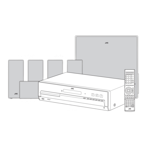
SERVICE MANUAL DVD DIGITAL CINEMA SYSTEM MB618 2007 7 S ERVICE MANUAL TH-D5B, TH-D5E, TH-D5EN, TH-D5EV SP-THD5W SP-THD5S SP-THD5F SP-THD5C XV-THD5 COPYRIGHT © 2007 Victor Company of Japan, Limited Lead free solder used in the board (material : Sn-Ag-Cu, melting point : 219 Centigrade) - Page 2 SPECIFICATION Center unit (XV-THD5) 140 W per channel RMS at 4 Ω at 1 kHz with 10 % total harmonic distortion. Output power Front 130 W RMS at 4 Ω at 1 kHz with 10 % total harmonic distortion. Center 130 W per channel RMS at 4 Ω...
- Page 3 Subwoofer (SP-THD5W) Type Bass-Reflex Type 16 cm cone × 1 Speaker Power Handling Capacity 140 W 4 Ω Impedance Frequency Range 30 Hz to 200 Hz Sound Pressure Level 75 dB/W•m Dimensions (W × H × D) 353.5 mm × 351 mm × 174 mm Mass 6.3 kg Satellite speakers...
-
Page 4: Precaution
SECTION 1 PRECAUTION Safety Precautions (1) This design of this product contains special hardware and voltmeter. many circuits and components specially for safety purpos- Move the resistor connection to each exposed metal es. For continued protection, no changes should be made part, particularly any exposed metal part having a return to the original design unless authorized in writing by the path to the chassis, and measure the AC voltage across... - Page 5 Preventing static electricity Electrostatic discharge (ESD), which occurs when static electricity stored in the body, fabric, etc. is discharged, can destroy the laser diode in the traverse unit (optical pickup). Take care to prevent this when performing repairs. 1.5.1 Grounding to prevent damage by static electricity Static electricity in the work area can destroy the optical pickup (laser diode) in devices such as laser products.
- Page 6 Important for laser products 1.CLASS 1 LASER PRODUCT 5.CAUTION : If safety switches malfunction, the laser is able to function. 2.CAUTION : (For U.S.A.) Visible and/or invisible class II laser radiation 6.CAUTION : Use of controls, adjustments or performance of when open.
-
Page 7: Specific Service Instructions
SECTION 2 SPECIFIC SERVICE INSTRUCTIONS This service manual does not describe SPECIFIC SERVICE INSTRUCTIONS. SECTION 3 DISASSEMBLY Main body 3.1.1 Removing the METAL COVER (See Fig.1, 2) (1) Remove the four screws A attaching the METAL COVER. (See Fig.1) (2) Remove the one screw B attaching the METAL COVER by use TORX driver. -
Page 8: No.mb618)1
3.1.3 Removing the AMP BOARD assembly (See Fig.4) (1) Disconnect the connector wire from POWER BOARD as- sembly connected to connector CN501 of the AMP CN501 CN504 BOARD assembly. (2) Remove the two screws K attaching the HEAT SINK BRACKET. (3) Remove the three screws L attaching the AMP BOARD as- sembly. - Page 9 3.1.5 Removing the FRONT PANEL assembly (See Fig.6 to 8) (1) Disconnect the card wire from FRONT PANEL assembly connected to connector CN211 of the MAIN BOARD as- CN211 sembly. (See Fig.6) (2) Remove the one screw N attaching the EARTH WIRE from FRONT PANEL assembly.
- Page 10 3.1.6 Removing the iPod BOARD assembly (See Fig.9) (1) Disconnect the card wire from iPod BOARD assembly con- nected to connector CN210 of the MAIN BOARD assem- bly. CN210 Fig.9 1-10 (No.MB618)
- Page 11 3.1.7 Removing the POWER BOARD assembly (See Fig.10 to 12) (1) Disconnect the connector wire from POWER BOARD as- sembly connected to connector CN151 of the MAIN BOARD assembly. (See Fig.10) (2) Disconnect the connector wires from POWER TRANS- FORMER connected to connector CN102 CN103 the POWER BOARD assembly.
- Page 12 3.1.8 Removing the MAIN BOARD assembly (See Fig.13) (1) Disconnect the connector wire from Fan connected to con- nector CN152 of the MAIN BOARD assembly. CN152 (2) Remove the four screws T attaching the MAIN BOARD as- sembly. Fig.13 3.1.9 Removing the USB BOARD assembly (See Fig.14) (1) Remove the two screws U attaching the USB BOARD as- sembly.
-
Page 13: No.mb618)1
3.1.10 Removing the VFD BOARD assembly (See Fig.15, 16) (1) Remove the two screws V attaching the BRACKET BOARD. (See Fig.15) (2) Remove the two screws W attaching the HEAD PHONE BOARD assembly. (See Fig.15) (3) Disconnect the card wire from TOUCH BOARD assembly connected to connector CN601 of the VFD BOARD assem-... - Page 14 DVD mechanism 3.2.1 Removing the traverse mechanism (See Fig.1 to 6) (1) Remove the two screws A attaching the tramecha holder from top side of DVD mechanism assembly. (See Fig.1) Clamper base (2) Remove the two screws B attaching the DVD module board.
- Page 15 DVD module board DVD module board CN101 CN201 Fig.6 Fig.3 DVD mechanism assembly Traverse mechanism assembly Fig.4 Solder short land section Fig.5 (No.MB618)1-15...
- Page 16 3.2.2 Removing the pickup assembly (See Fig.7 to 11) (1) Remove the two rod springs pressing the guide shaft. (See (SHAFT) Fig.7) (2) Remove the screw E and F attaching the spring holder. (See Fig.8) (T.TABLE) (3) Remove the read screw from traverse mechanism assem- bly.
- Page 17 3.2.3 Removing the feed motor assembly (See Fig.12) (1) Remove the one screw G attaching the feed motor assem- Splder part bly. (2) Remove the feed motor wires from solder part of spindle motor board. Middle gear Lead screw Fig.12 3.2.4 Removing the spindle motor assembly (See Fig.13) (1) Remove the three screws H attaching the spindle motor...
- Page 18 3.2.5 Removing the tray assembly (See Fig.14 & 15) (1) Remove the two screws J attaching the clamper base. (See Fig.14) (2) Remove the one screw K attaching the shaft guide from bottom side. (See Fig.14) (3) Remove the two screws L attaching the shaft guide from top side.
-
Page 19: Adjustment
SECTION 4 ADJUSTMENT ATTENTION IN SERVICE OF DVD SECTION (1) When pickup, Flash ROM ,DVD module board were changed, initialize EEPROM by all means. (2) When full initialization was executed, execute learning with a DVD test disc by all means. Test disc : VT-501, VT-502 Learning method : It is adjusted automatically by normal playback of a DVD disc. - Page 20 FL(LCD)indication STEP Operation Movement Remarks 0x04: BCA CHECK OK incomplete DVD learning complete CD leaning complete (indication 4) 0x03: BCA CHECK OK complete DVD learning incomplete CD learning incomplete (indication 3) 0x02: BCA CHECK OK complete DVD learning complete CD learning incomplete (indication 2) 0x01: BCA CHECK OK complete DVD learning incomplete CD learning complete...
- Page 21 FL(LCD)indication STEP Operation Movement Remarks Press a [4] key of the 10 CD_LD lights and laser Upper : Laser current value key on remote controller current is displayed (BACKUP value,Real measured value) Lower : 0 Upper : Laser current value Press a [5] key of the 10 DVD_LD lights and laser (BACKUP value,Real measured value)
- Page 22 KEY special mode MODE NAME STATUS OPERATION FUNCTION P.OFF Change to 9kHz step by TUNER 9K/10kHz TUNER AM 9kHz/10kHz step select. select (U ver) press and hold [+] key, Indicate "9k STEP", "10k STEP". then press [|<<] key. P.OFF Change to 10kHz step by press and hold [+] key, then press [>>|] key.
-
Page 23: Troubleshooting
TH-D SPECIAL MODE Ver 0.2 POWER EJECT B.SKIP F.SKIP SOURCE MODE SET STATUS KEY1 KEY2 OPERATION DVD TEST MODE AC OFF SOURCE POWER AC IN TRAY LOCK STANDBY Press and keep [+] key EJECT TUNE 9K STANDBY Press and keep [+] key B.SKIP TUNE 10K STANDBY... - Page 24 Victor company of Japan, Limited Audio/Video Systems category 10-1,1chome,Ohwatari-machi,Maebashi-city,371-8543,Japan (No.MB618) Printed in Japan...
- Page 25 SCHEMATIC DIAGRAMS DVD DIGITAL CINEMA SYSTEM TH-D5B,TH-D5E,TH-D5EN TH-D5EV CD-ROM No.SML200707 SP-THD5W SP-THD5S SP-THD5F SP-THD5C XV-THD5 Lead free solder used in the board (material : Sn-Ag-Cu, melting point : 219 Centigrade) Lead free solder used in the board (material : Sn-Cu, melting point : 230 Centigrade)
- Page 26 In regard with component parts appearing on the silk-screen printed side (parts side) of the PWB diagrams, the parts that are printed over with black such as the resistor ( ), diode ( ) and ICP ( ) or identified by the " " mark nearby are critical for safety.
-
Page 27: Block Diagram
Block diagram DVD section DVDOUT0 to 7, H_AOUT0 to 2, H_TX, SCK, SDA CPURST, HCLK, VCLKO, H_BCK, H_LRCK, H_MCLK A, B, C, D, E, F, RF+, LPC1, LPC2 TX_HPD IC902 LD(CD) LPCO1, LPCO2 SCL, SDA TX_SCL, TX_SDA DVD pickup LD(DVD) Q101 to Q104 CDLDCUR, DVDLDCUR Q901 to Q903... - Page 28 GNA10048-A1 Standard schematic diagrams POWER TRANSFORMER F1201/F1202 Primary section QMF51U1-100-J8 (J/C) AC41.6V FC122 FC121 F1201 AC15.8V QNG0003-001Z QNG0003-001Z FC124 FC123 F1202 AC15.8V GNA10048-A1 AC41.6V QNG0003-001Z QNG0003-001Z QGA3901C1-05 C1201 CN103 C1213 0.1/50 0.1/50 C1202 0.1/50 CN102 D1201 GBU803 CN104 with Heatsink QGA2502C1-05 AC11.4V AC11.4V...
- Page 29 FOR HDMI System control section FOR HDMI PASSTHRU FOR DVD MECHA FOR DVD MECHA FOR TUNER QGF1016C6-26W CN203 CN204 CN205 QGF1016C6-18W QGF1036C2-08 QGF1016C6-09W QGF1208C1-15 CN201 CN202 GNA10049-A1 W3007 R2164 D4/D5/D50 AGND2 D6/D60 R2165 5.6k B,E,EN,EV OTHERS /D7/D70/D8 AGND R2166 4.7k C1624 R2914 R2167...
- Page 30 Master Volume IC section GNA10049-A1 LEVEL DETECT IC301 (1/2) NJM4565M-WE C3007 R3016 5.4V ONLY FOR D6/D60/D7/D70 C3002 R3006 R3008 5.5V C3533 K3601 4.7/50 N.I. R3531 C3531 5.5V C3601 NQR0022-005X R3533 IC361 ONLY FOR D6/D60/D7/D70 220/10 TC74LCX04FT-X 270k 4.7/50 Q3532 0.01/50 R3532 C3532 5.4V...
- Page 31 RT1N441C-X RT1P141C-X Video Input/Output section GNA10049-A1 RT1N141C-X ONLY FOR B/E/EN/EV C4501 AUDIO R OUT R4501 AUDIO R IN W3011 AUDIO L OUT US6V 4.7/50 AUDIO AGND C4531 Q4521 R4524 C4511 R4511 AV10V AUDIO L IN RT1P141C-X R4531 4.7/50 FUNCTION Q4522 R4521 RT1N141C-X R4532...
- Page 32 Power amplifier section G N A 1 0 0 5 0 - A 1 I C 5 0 1 S T K 4 1 6 - 1 3 0 - E I C 5 0 2 S T K 4 1 6 - 1 3 0 - E S W c h S L c h S R c h...
- Page 33 FL/ User key control section GNA10048-2 R2501 R2511 R2521 100K 100K CN601 100K QGF1036F2-09 R2505 R2515 R2525 DI601 9.9V A10V FL DISPLAY QLF0189-001 4.2V PLAY-LED 5.0V PLAY 9.3V 9.3V C2501 C2511 9.3V C2521 4.2V STOP-LED To CN641 of 220/16 220/16 220/16 9.9V DGND...
- Page 34 Headphone/USB/Mic control section From CN604 of GNA10048-A2 From CN603 of GNA10048-A2 FW613 CN711 GNA10049-A3 GNA10048-A4 QUM024-07Z4Z4-E QGF1040F1-07 MIC JACK PWB (EE,UB,UG,UJ,US,UT,UW,UX) USB Jack Headphone Jack J7501 C7505 QNZ0906-001 1/16 CN751 J7001 WJP0093-005A-E QNS0276-001 K7501 VBUS C7506 NQR0502-001X 1/16 K7502 NQR0022-002X K7503 NQR0022-002X K7504...
- Page 35 XM-READY control section LVA10683-A1 ONLY FOR D60J,C / D70UJ XM READY PWB C9012 C9013 5p/50 5p/50 X9001 NAX0161-002X 45.1584MHz R9013 3.3k R9012 R9015 DGND SDATA R9016 R9018 C9011 SYNK R9017 SCLK C9017 FMT1 0.1/16 C9016 MDAT FMT0 0.1/16 MONO DGND R9014 AUDIO EMPH...
- Page 36 DVD control section (1/4) K354 NQR0022-002X R318 K355 NQR0022-002X 48MHz R327 HCLK C370 D1.2V REG. C328 0.01 DVDPWR 3.9V D1.2V Cont DVDPWR P3.3V 1.2V C302 47/4 IC302 MM1701CH-X CN301 QGA1002C1-06X for ICE D301 RB521S-30-X DGND CPURST RESET EEPROM R306 SCLK C564 DGND R307...
- Page 37 DVD control section (2/4) SDRAM C552 FLASH ROM IC505 IC509 IC512 SG32A90TFIR3 K4S641632K-UC75 TC74LCX373FT-X LADR15 0.4V 0.5V EXADR16 C560 3.3V LADR14 0.7V 3.3V LADR0 LADR7 2.8V 2.7V MDQ15 MDQ0 */BYTE DQ15 LADR13 0.5V EXADT0 EXADT7 C551 3.3V VDDQ VSSQ LADR12 0.7V 0.8V EXADT1...
- Page 38 DVD control section (3/4) P3.3V DGND R859 R860 Q801 UN2113X IC801 MM1565AF-X KRA104S-X R891 Vout IC891 Cont C819 CN811 QGA2001F6-05X R819 R811 1/2W K811 R812 K812 1/2W LVA10660-501B (3/4) NOTES VOLTAGES ARE DC-MEASURED WITH A DIGITAL VOLT METER WITHOUT INPUT SIGNAL. NI STANDS FOR NOT INSERTED PARTS.
- Page 39 DVD control section (4/4) Loader section HD3.3V K906 NQR0502-001X C922 C916 CN802 DGND CN801 QGF1016C6-09W HA3.3V TP951 C950 C951 C952 C953 C954 C955 C956 TP952 K905 TP953 QSW1074-001 NQR0502-001X C921 C914 For TX5V HGND TP915 124 DO29 AVSS QGF1016F3-05 125 RXSENSE TX2P 126 PCLKOUT TX2M...
- Page 40 Printed circuit boards Main board Lead free solder used in the board (material : Sn-Ag-Cu, melting point : 219 Centigrade) forward side Lead free solder used in the board (material : Sn-Cu, melting point : 230 Centigrade) R1903 C1702 C1613 D1624 IC161 Q1903...
- Page 41 Main board Lead free solder used in the board (material : Sn-Ag-Cu, melting point : 219 Centigrade) reverse side Lead free solder used in the board (material : Sn-Cu, melting point : 230 Centigrade) Q1611 R1903 R1614 D1624 C1702 C1612 Q1901 R1702 (Main board)
- Page 42 Power board Lead free solder used in the board (material : Sn-Ag-Cu, melting point : 219 Centigrade) Lead free solder used in the board (material : Sn-Cu, melting point : 230 Centigrade) (Connection board) (Power board) R1002 HS121 C1210 CN524 C1208 C1205 C1211...
- Page 43 Amp board Lead free solder used in the board (material : Sn-Ag-Cu, melting point : 219 Centigrade) Lead free solder used in the board (material : Sn-Cu, melting point : 230 Centigrade) D5101 D5501 D5201 D5601 D5301 R5108 D5401 R5408 R5208 C5102 R5201...
- Page 44 DVD board Loader board Lead free solder used in the board (material : Sn-Ag-Cu, melting point : 219 Centigrade) Lead free solder used in the board (material : Sn-Ag-Cu, melting point : 219 Centigrade) Lead free solder used in the board (material : Sn-Cu, melting point : 230 Centigrade) Lead free solder used in the board (material : Sn-Cu, melting point : 230 Centigrade) forward side R990...
- Page 45 < M E M O >...
- Page 46 Victor Company of Japan, Limited Audio/Video Systems Category 10-1,1chome,Ohwatari-machi,Maebashi-city,371-8543,Japan Printed in Japan (No.MB618SCH)
-
Page 47: Parts List
PARTS LIST TH-D5B,TH-D5E,TH-D5EN TH-D5EV * All printed circuit boards and its assemblies are not available as service parts. - Contents - 3- 2 Exploded view of general assembly and parts list (Block No.M1) 3- 6 DVD mechanism assembly and parts list (Block No.MJ) 3- 8 DVD loading base assembly and parts list (Block No.MN) - Page 48 Exploded view of general assembly and parts list Block No. LED board USB board Touch board VFD board Head phone board iPod board...
- Page 49 46 47 54 AMP board Main board D board Power board The parts without symbol number are not service.
- Page 50 General Assembly Block No. [M][1][M][M] Symbol No. Part No. Part Name Description Local GN10122-003A FRONT PANEL GN10123-018A ARNAMENT GN20231-001A PUSH BUTTON GN20233-005A WINDOW SCREEN LV42851-012A FL SCREEN GN30223-003A LENS LV30227-0A7A SPACER QYSDSF2608ZA TAP SCREW M2.6 x 8mm(x2) GN40140-001A LENS(DVD) GN40152-001A SENSOR SPACER QYSDSF2608ZA...
- Page 51 Symbol No. Part No. Part Name Description Local QUR110-0907AE-E FFC WIRE FFC 3 QUR110-0512AE-E FFC WIRE FFC 6 QUR310-1310AE-E FFC WIRE FFC 7 LV30227-0A5A SPACER LV37706-019A RATING LABEL LV30225-0M8A SPECER QMF51W2-2R5-J8 FUSE F 1001 2.5A AC250V QMF51W2-6R3-J8 FUSE F 1201 6.3A AC250V QMF51W2-6R3-J8...
- Page 52 DVD mechanism assembly and parts list Block No. Grease FXL-D10-11M =JVG-31N =JVS-1003 =1401C < Back side > 7.0mm 0.2mm The parts without symbol number are not service.
- Page 53 DVD mechanism Block No. [M][J][M][M] Symbol No. Part No. Part Name Description Local LV22234-001A TM.CHASSIS LV22235-001A SPINDLE BASE QYSDST2005ZA TAP SCREW M2 x 5mm(x2) LV36555-001A G.S.HOLDER QYSDST2005ZA TAP SCREW M2 x 5mm LV44041-002A GUIDE SHAFT LV44479-001A BAR SPRING LV22236-001A FEED HOLDER QAR0165-001 FEED MOTOR...
- Page 54 DVD loading base assembly and parts list Block No. FMU-MB5-1M Grease JVS-1003 CFD-4007ZY2 < Back side > < In side > Backside DVD loading switch board DVD module board The parts without symbol number are not service.
- Page 55 DVD loading base Block No. [M][N][M][M] Symbol No. Part No. Part Name Description Local LV11065-010A LOADER SUB ASSY E407140-001SS C.D ROLLER E407149-001SS RUBBER TUBE LV10979-003A TRAY LV35499-003A SHAFT GUIDE LV44022-001A SHAFT QYSSSF2008ZA TAP SCREW M2 x 8mm QYSDSF2008ZA TAP SCREW M2 x 8mm(x2) LV41741-004A SPECIAL SCREW...
-
Page 56: Electrical Parts List
Electrical parts list Main board Symbol No. Part No. Part Name Description Local Block No. [0][1] D2003 MA152WA-X DIODE Symbol No. Part No. Part Name Description Local D2004 1SS355W-X DIODE D2005 MA152WA-X DIODE D2006 UDZW3.9B-X Z DIODE IC161 PQ1CG21H2FZ Regulator D2007... - Page 57 Symbol No. Part No. Part Name Description Local Symbol No. Part No. Part Name Description Local C3206 QETN1HM-475Z E CAPACITOR 4.7uF 50V M C4206 QETN1CM-226Z E CAPACITOR 22uF 16V M C3207 QETN1HM-475Z E CAPACITOR 4.7uF 50V M C4207 NCB30JK-105X C CAPACITOR 1uF 6.3V K...
- Page 58 Symbol No. Part No. Part Name Description Local Symbol No. Part No. Part Name Description Local R2114 NRSA63J-103X MG RESISTOR 10kΩ 1/16W J R2803 NRSA63J-221X MG RESISTOR 220Ω 1/16W J R2115 NRSA63J-222X MG RESISTOR 2.2kΩ 1/16W J R2903 NRSA63J-0R0X MG RESISTOR 0Ω...
-
Page 59: Amp Board
Symbol No. Part No. Part Name Description Local Symbol No. Part No. Part Name Description Local R3544 NRSA63J-220X MG RESISTOR 22Ω 1/16W J R6704 NRSA63J-105X MG RESISTOR 1MΩ 1/16W J R3545 NRSA63J-103X MG RESISTOR 10kΩ 1/16W J R6705 NRSA63J-562X MG RESISTOR 5.6kΩ... - Page 60 Symbol No. Part No. Part Name Description Local Symbol No. Part No. Part Name Description Local D5002 MTZJ15C-T2 Z DIODE C5914 NCB31HK-471X C CAPACITOR 470pF 50V K D5003 SB360-C332-3 SB DIODE C5921 NCB31HK-104X C CAPACITOR 0.1uF 50V K D5003 SB360-F82 SB DIODE...
-
Page 61: Power Board
Symbol No. Part No. Part Name Description Local Symbol No. Part No. Part Name Description Local R5409 NRSA63J-102X MG RESISTOR 1kΩ 1/16W J J5001 QNB0319-001 SPK TERMINAL R5410 NRSA63J-563X MG RESISTOR 56kΩ 1/16W J RY591 QSK0127-001 RELAY R5501 NRSA63J-563X MG RESISTOR 56kΩ... - Page 62 Symbol No. Part No. Part Name Description Local Symbol No. Part No. Part Name Description Local C2511 QEKC1CM-227Z E CAPACITOR 220uF 16V M R6105 NRSA63J-241X MG RESISTOR 240Ω 1/16W J C2512 NCF31AZ-105X C CAPACITOR 1uF 10V Z R6106 NRSA63J-103X MG RESISTOR 10kΩ...
- Page 63 Symbol No. Part No. Part Name Description Local Symbol No. Part No. Part Name Description Local K7604 NQR0022-002X FERRITE BEADS C257 NCB31HK-822X C CAPACITOR 8200pF 50V K K7605 NQR0022-002X FERRITE BEADS C258 NCB31CK-153X C CAPACITOR 0.015uF 16V K K7606 NQR0502-001X FERRITE BEADS...
- Page 64 Symbol No. Part No. Part Name Description Local Symbol No. Part No. Part Name Description Local C562 NCF31AZ-105X C CAPACITOR 1uF 10V Z R108 NRSA63J-471X MG RESISTOR 470Ω 1/16W J C563 NCB31CK-104X C CAPACITOR 0.1uF 16V K R109 NRSA63J-331X MG RESISTOR 330Ω...
- Page 65 Symbol No. Part No. Part Name Description Local Symbol No. Part No. Part Name Description Local R371 NRSA63J-103X MG RESISTOR 10kΩ 1/16W J R978 NRSA63J-103X MG RESISTOR 10kΩ 1/16W J R372 NRSA63J-103X MG RESISTOR 10kΩ 1/16W J R980 NRSA63J-472X MG RESISTOR 4.7kΩ...
- Page 66 Packing materials and accessories parts list Block No. No additional / supplemental order of WARRANTY CARDs are available. A2(Only E,EN), A3, A4(Only B), A7, A8, Only B Bottom View Only B A20, A21, A22, A23, A24, The parts without symbol number are not service. 3-20...
- Page 67 Packing and Accessories Block No. [M][3][M][M] Symbol No. Part No. Part Name Description Local LVT1704-003A INST BOOK LVT1704-004A INST BOOK GER FRE LVT1704-006A INST BOOK DAN FIN SWE LVT1704-008A INST BOOK HUN CZE POL LVT1704-005A INST BOOK ITA DUT LVT1704-007A INST BOOK SPA POR...
Need help?
Do you have a question about the TH-D5B and is the answer not in the manual?
Questions and answers