Table of Contents
Advertisement
Advertisement
Table of Contents

Related Manuals for Wellsaw 1016


Summary of Contents for Wellsaw 1016
-
Page 1: Parts List
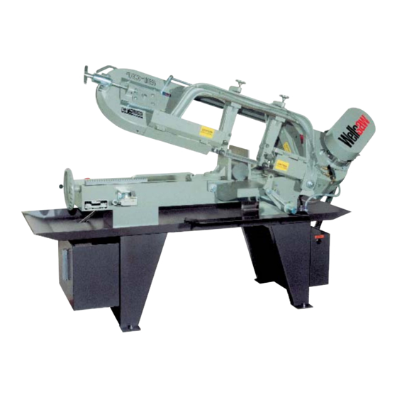
1016 Parts List Manual Bandsaw Built better to work stronger and last longer Operating & Maintenance Manual Rev 4-13 REV 170607 2829 N. Burdick St. Kalamazoo, MI 49004 Burdick St. Kalamazoo, MI 49004 Phone: 269-345-1132 Fax: 269-345-0095 269-345-1132 Fax: 269-345-0095... -
Page 2: Receiving & Installation
Electrical codes differ from area to area and it is the customer’s responsibility to ensure that their saw complies with applicable codes. Your Wellsaw is pre-wired at the factory for a specified voltage. Always check the motor and electrical panel to ensure that they are both wired to correspond to your electrical power supply. -
Page 3: Machinery General Safety Warnings
- Always keep machine guards in place. full benefits from your machine. Used properly, - Always put start switch in “OFF” position before Wellsaw’s machinery is among the best in design and plugging in machine. safety. However, any machine used improperly can be rendered inefficient and unsafe. -
Page 4: Safety Instructions
General Electrical Cautions 19. Some dust created by power sanding, sawing, grinding, This saw should be grounded in accordance with the National drilling and other construction activities contains chemicals Electrical Code and local codes and ordinances. This work known to cause cancer, birth defects or other reproductive should be done by a qualified electrician. -
Page 5: Table Of Contents
Specifications Index General Capacity: Automatic Stop Round 10½” Blade Brushes Flat 16½” Blade Selection Guide 36-37 Rectangular 10" x 16" Feed Pressure Adjustment 45 10" x 9" Fixed Vise Jaw Gear Box Repair Blade Speeds 50-100-175-275 SFPM Hydraulic Feed Control Lubrication Motor Maintenance... -
Page 6: Notes On Sawing
Notes on Sawing Trouble Shooting Premature Dulling of Blade Teeth It is widely recognized that a proficient operator is a key to optimum bandsawing. He makes certain the machine is properly maintained and adjusted for dependable operation. 1. Feed rate too high or low. Check recommendation. He carefully sets up each cutting job to prevent damage to the 2. -
Page 7: Automatic Stop
9. Dirty coolant. Premature Blade Breakage 10. Check for loose fasteners. 1. Poor weld in the blade. Rough Cut / Poor Finish 2. Feed rate set too high. Reduce it. 3. Excessive blade speed. Adjust it. 4. Blade guides set too tight or misaligned. 1. -
Page 8: Fixed Vise Jaw
Variable Speed Drive carbide block away from the blade. 6. Remove the blade. Always wear gloves when handling Model 1016 may be equipped with variable speed pulleys bandsaw blades. providing infinite speed selection between 70 and 375 feet- 7. Install the blade on the bandwheels making sure the teeth per-minute. -
Page 9: Maintenance Instructions
it stops. It does not need to be tight. Be sure that the band Blade Guide Alignment is not riding up on the bandwheel flange. Up to S/N 2499 8. Begin tightening the Rite Tension® device by turning “T” handle Clockwise (CW). Pull out on handle while To properly align the saw blade for a straight and accurate cut, tightening. -
Page 10: Blade Brushes
3. Horizontal Adjustment. Loosen the two cap screws [B] blade. To open the roller guide while inserting a new blade, securing the horizontal adjusting block (items 11 & 12 of the pull down on the knurled brass housing and rotate it. After parts drawing). -
Page 11: Lubrication
1 req’d. Correct and adequate lubrication is a very important factor M-426 Blade Brush 2 req’d. in determining the life and service of your Wellsaw. It is M-166 Dash Pot Cup Leather 1 req’d. essential that all dust, dirt, chips, etc. -
Page 12: Warranty
Within one year from the date of purchase, we will, free of charge, at our option, either repair or replace any part of the Wellsaw which our examination discloses to be defective because of workmanship or a defect in material, and to make any necessary service adjustments as required. -
Page 13: Machine Operation
NOTE: If the coolant selector switch is in the ON position, the coolant pump will turn on with the motor. Check to ensure there is adequate coolant in the coolant tank. 4. Adjust frame weight for the material to be cut. Refer to the Wellsaw “Select-O-Chart” for the recommended settings. (L = light, M = medium, H = heavy) 5. -
Page 14: Frame Assembly
Frame Assembly (see page 29) new style blade brush assembly 1016FrameAssem-2 for serial numbers before 3319 see pg 17... -
Page 15: Frame Assembly
Frame Assembly 155108 Back Blade Guard 100063 Thumb Screw 100034-001 Set Screw, 1/4-20 x 3/16 (2 req'd) M-102 Sliding Weight Post B-101 Sliding Weight Bar 100000-024 Machine Screw, RH, 1/4-20 x 3/8 100025-001 Lock Washer, 1/4 M-857 Sliding Weight Spring M-807 Sliding Weight 100042-005... -
Page 16: Bed Assembly
Bed Assembly 17 18 17 18 Dash Pot 14 15 31 30 66 68 18 45 66 68 69 Old Version... -
Page 17: Bed Assembly
Bed Assembly 1 155022 Dash Pot, Upper Stud 2 M-301 Dash Pot Assembly used before 54 54 155012 Saw Bed used before s/n 5382 sn 3100 (see page 27) 155012-001 Saw Bed used after s/n 5382 3 101526 Piston Rod Assembly used before 55 Electrical Controls (see page 33) sn 3100 (includes items 7-11) 56 56 B-011... -
Page 18: Blade Guide Assembly
Blade Guide Assembly Serial Numbers up to 2499 Drive End Idle End blade brush assy before s/n 3318 for s/n after 3318 see pg 13 Guide-A-Matic© CAUTION: Most questions to our service department about the Guide-A-Matic© involve roll-pin alignment. Roll-pin (9) must be in the proper place for the Guide-A-Matic to operate. -
Page 19: Guide-A-Matic Assembly
Blade Guide Assembly Serial Numbers up to 2499 155119 Coolant Assembly (see page 23) 105412 Blade Guide Assembly, Idle End (includes items 7-23) 105409 Blade Guide Assembly, Drive End (includes items 7-22 and 24) 105367 Guide-A-Matic Assembly (see bottom of this page) 105414 Roller Support Assembly, Idle End (includes items 15-23) - Page 20 Carbide Guides Up to Serial Number 2499 (option) 12/13 M1016CarbideGuide...
- Page 21 Carbide Guides Up to Serial Number 2499 (option) 101522-002 Blade Guide Assembly, D.E. (includes items 5-27 minus 13) 105406-002 Blade Guide Assembly, I.E. (includes items 5-27 minus 12) 150061 Guide Support Assembly, D.E. (includes items 12-27 minus 13) 106659 Guide Support Assembly, I.E. (includes items 13-27) 105335-001 Hand Wheel &...
-
Page 22: Blade Guides
Blade Guides Serial Number 2500 and Later blades guides-2... - Page 23 Blade Guide Assembly Serial Number 2500 and Later 155124 Blade Guide Assembly, Drive End (includes items 5-27, and 29, minus 7 and 12) 155125 Blade Guide Assembly, Idle End (includes items 5-28, minus 6 and 11) 152160-001 Guide Support Assembly, Drive End (includes items 13-27 and 29) 152161-001 Guide Support Assembly, Idle End (includes items 13-28)
-
Page 24: Coolant System
Coolant System Leg & Chip Pan... -
Page 25: Coolant System
Coolant System Leg & Chip Pan... -
Page 26: Rite Tensioning Device
Rite Tensioning Device® Calibrating the WELLSAW RITE-TENSION ® Blade Tensioning Device The Rite-Tension® device is a simple turn counter that is activated by blade tension and can be easily adjusted in the field. Please review the operation instructions before making any adjustment: 1. -
Page 27: Rite Tensioning Device
Rite Tensioning Device® Caution: The Rite Tension ® blade tensiong device has been factory calibrated for your saw. When re-tightening or replacing a blade, the 'T' handle must be turned counter-clockwise at least six turns to reset the Rite Tension ® mechenism. 150075 Blade Tensioning Ass'y (includes items 2 thru 17) -
Page 28: Hydraulic System
Hydraulic System Dash Pot 14 35 155114 M-301 155151 Part no. 155144 is no longer available. 155329 Use part no. 155151. 155329 (Parts for 155154 are still available.) M1016HydCyl... -
Page 29: Hydraulic System
Hydraulic System M-301 Dash Pot Assembly (before S/N 3319, includes items 4-11 and 54) 101526 Piston Rod Assembly (includes 6-9) 155022 Dash Pot Mounting Stud M-144 Piston Rod End 101524 Outside Tube 101527 Piston Rod M-166 Cup Leather 100070 Cup Washer M-148 Spring 100050-002... -
Page 30: Motor & Gear Box
1016 Motor & Gear Box 100318-005 Gearbox grease 1016Motor&GearBox... -
Page 31: Motor & Gear Box
1016 Motor & Gear Box Starting S/N 2760 the 1016 gear box began 150428 Belt Guard (starting S/N 3100) using two bearings (item 23) in the cover 105531 Belt Guard (before S/N 3100) (item 21) and a snap ring (item 22) at the... -
Page 32: Variable Speed Drive
Variable Speed Drive 16 15 39 40 grease for gearbox... -
Page 33: Variable Speed Drive
Variable Speed Drive 407-712 Hand Wheel 150217 Spacer 100008-087 Cap Screw, SH, 1/4-28 x 3/4 150256 Blade Speed Indicator w/Pointer 150255 Flange Clamp 155109 Belt Cover 150252 Sleeve 105688 Blade Speed Label 100013-006 Machine Screw, BH, 1/4-20 x 1/2 (4 req'd) 100025-001 Flat Washer, 1/4 105454-004... -
Page 34: Electrical Controls
Electrical Controls M1316ElecControls-2... -
Page 35: Electrical Controls
100606-001 Sealing Ring to make certain you receive the correct replacement 100612-006 Elbow, 90 deg, TB-2268 parts, contact the Wellsaw parts department with the 100015-005 Hex Nut, 6-32 (2 req'd) information on your saw's starter. 100026-001 Washer, Shake Proof, #6 (2 req'd) - Page 36 Electrical Schematic Electrical Schematic...
- Page 37 Stock Dimensions 0 - 1" 1" - 3" 3" - 6" 6"+ Tooth Pitch 10/14, 8/12 8/12, 6/10, 5/8 5/8, 4/6, 3/4, 3 Sabre 3/4, 2/3, 2 Sabre, 1 Tooth, 3/4" T.S. Material (Annealed) Blade Cutting Blade Cutting Blade Cutting Blade Cutting Speed...
- Page 38 Stock Dimensions 0 - 1" 1" - 3" 3" - 6" 6"+ Tooth Pitch 10/14, 8/12 8/12, 6/10, 5/8 5/8, 4/6, 3/4, 3 Sabre 3/4, 2/3, 2 Sabre, 1 Tooth, 3/4" T.S. Material (Annealed) Blade Cutting Blade Cutting Blade Cutting Blade Cutting Speed...
- Page 39 The Original..Since 1926 2829 N. Burdick St. Kalamazoo, MI 49004 Phone: 269-345-1132 Fax: 269-345-0095 website: www.wellsaw.com email: parts@wellsaw.com...
Need help?
Do you have a question about the 1016 and is the answer not in the manual?
Questions and answers