Table of Contents
Advertisement
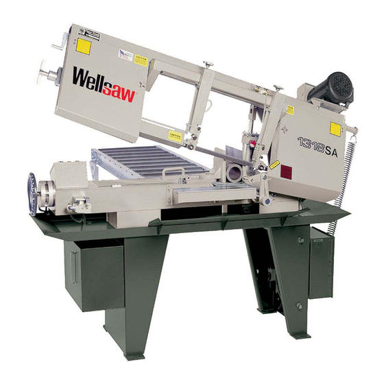
1318-SA
(formerly model 1118-SA)
Parts List
Semi Automatic Bandsaw
and
Built better to work stronger and last longer
Operating & Maintenance Manual
Rev 150330
2829 N. Burdick St. Kalamazoo, MI 49004
ck St. Kalamazoo, MI 49004
Phone: 269-345-1132 Fax: 269-345-0095
345-1132 Fax: 269-345-0095
www.wellsaw.com
Advertisement
Table of Contents

Related Manuals for Wellsaw 1318 -SA


Summary of Contents for Wellsaw 1318 -SA
-
Page 1: Parts List
(formerly model 1118-SA) Parts List Semi Automatic Bandsaw Built better to work stronger and last longer Operating & Maintenance Manual Rev 150330 2829 N. Burdick St. Kalamazoo, MI 49004 ck St. Kalamazoo, MI 49004 Phone: 269-345-1132 Fax: 269-345-0095 345-1132 Fax: 269-345-0095 www.wellsaw.com... -
Page 2: Table Of Contents
Index Specifications General Automatic Stop Capacity: Blade Brush Rectangular 13" high x 18" wide Blade Selection Guide 38-39 Feed Pressure Adjustment Round 13" diameter Fixed Vise Jaw Gear Box Repair Flat 18" wide Hydraulic Feed Control Lubrication 45°Angle 13" high x 9-1/2" wide Maintenance Hydraulic bleeding instructions Blade Speed... -
Page 3: Warranty
Parts Order For your convenience: When contacting your Wellsaw Supplier or the Company for parts or service, it is essential that you have your Model and Serial Numbers and Purchase Date available. Jot them down here for handy reference. -
Page 4: Set Up And Operation
Wellsaw Semi Automatic Bandsaw Set up and Operation Items needed: Electrical power 7 gallons of water Compressed air, 5 CFM @ 100 PSI Air tool oil for air lubricator. Prior to start up Warning! Do not lift saw frame with your hand! Saw frame is raised with a powered system. - Page 5 Raise button until limit switch stops frame. ( Repeat this adjustment at a later time until frame is in the desired position above stock.) Turn the Vise Control knob to AOpen@. Pick up the lift handle on adjustable vise and pull the vise open enough to move stock into place.
-
Page 6: Machinery General Safety Warnings
- Always keep machine guards in place. full benefits from your machine. Used properly, - Always put start switch in “OFF” position before Wellsaw’s machinery is among the best in design and plugging in machine. safety. However, any machine used improperly can be rendered inefficient and unsafe. -
Page 7: Safety Instructions On Sawing Systems
General Electrical Cautions 19. Some dust created by power sanding, sawing, grinding, This saw should be grounded in accordance with the National drilling and other construction activities contains chemicals Electrical Code and local codes and ordinances. This work known to cause cancer, birth defects or other reproductive should be done by a qualified electrician. -
Page 8: Notes On Sawing
Notes on Sawing Trouble Shooting It is widely recognized that a proficient operator is a key to optimum bandsawing. He makes certain the Premature Dulling of Blade Teeth machine is properly maintained and adjusted for dependable operation. He carefully sets up each Feed rate too high or low. -
Page 9: Automatic Stop
Premature Blade Breakage 6. Blade guides loose, worn or out of alignment. 1. Poor weld in the blade. 7. Too many teeth-per-inch. Blade not cutting 2. Feed rate set too high. Reduce it. freely. 3. Excessive blade speed. Adjust it. 8. -
Page 10: Feed Pressure Adjustment
increase speed or counter-clockwise to decrease PLACING THE BLADE ON SAW speed. Do not adjust the speed unless the pulley system is in operation (spinning). The handwheel To insert a new blade, turn the Adjusting Knob drag is set at the factory during assembly. This drag (item 17 in the parts diagram) on the blade guide prevents handwheel “creep”... -
Page 11: Blade Brush
Blade Brush The brush should be cleaned frequently in of adjustment needed in the Horizontal Adjusting kerosene and reversed to extend effectiveness. For Block. The Idle End adjusting block is more likely efficient cutting and blade life, keep blade brush to require adjustment. -
Page 12: Lubrication
3. Inspect gear box. Lubricate as needed. Lubrication Correct and adequate lubrication is a very impor- tant factor in determining the life and service of your Wellsaw. It is essential that all dust, dirt, chips, etc. be thoroughly removed before lubricat- ing the saw. - Page 13 Instructions to Bleed Hydraulic System Wellsaw models: 1118SA, 1318 SA, 1316S SA, Also saws with Powered Frame Lift Option Air can enter the system through a leak or if the system is run with low oil level. Also, if the saw head is lifted manually air can enter the system.
-
Page 14: Frame Assembly
Frame Assembly 70 22 29 33 M1118 Frame Assembly... -
Page 15: Frame Assembly
Frame A Frame Frame Assembly 1 150146SERV Idle Wheel Guard 2 150147SERV Drive Wheel Guard 3 100139-003 Knob 4 100034-045 Set Screw, 1/4-20 x 1-1/4 5 150150 Retainer Nut 6 100135-002 1/4 Turn Fastener w/cam (after S/N 2583) 55 100025-001 Lock Washer, 1/4 7 100013-006 Machine Screw, BH 1/4-20 x 1/2... -
Page 16: Bed Assembly
Bed Assembly 55 54 53 55 54 53 M1118SABedAssm... -
Page 17: Bed Assembly
Bed Assembly Bed Assembly 1 100004-044 Cap Screw, HH 5/8 x 3 45 100009-006 Cap Screw, Flat SH 3/8-16 x 1 2 B-003 Movable Vise Jaw 46 B-082 Stop Bar Bracket 3 155107 Washer 47 100033-015 Set Screw, Sq Hd 5/8-11 x 1 4 100004-070 Cap Screw, HH 1/2-13 x 1-3/4 48 100025-007... -
Page 18: Leg & Chip Pan
Leg and Chip Pan 14 15 M1118SALeg&ChipPan... -
Page 19: Leg & Chip Pan
Leg and Chip Pan 1 F-228 Splash Guard 2 155169 Chip Pan 3 152005 Leg, Drive End 4 155177 Leg, Idle End Coolant Tank Assembly (see page 26) 6 150081 Spring Anchor 7 150466 Counter Balance Spring 8 150078 Coolant Tank Hanger (2 req'd) 9 100004-003 Cap Screw, HH 1/4-20 x 1/2 (2 req'd) 10 100025-001... -
Page 20: Frame Lift
Frame Lift 1118SA Bed M1118SAFrameLift... -
Page 21: Frame Lift
Frame Lift 1 155218 Cylinder Assembly (includes items 2 - 24) 2 099000-008 Cylinder, 7.5" Stroke, 2.5" Bore 3 152096 Clevis 4 100069-019 Snap Ring (2 req'd) 5 152164 Clevis Pin 6 100019-016 Hex Nut, Jam, 5/8-18 7 152097 Switch Trip Rod 8 100053-021 Roll Pin, 3/16 x 7/8 9 152098... -
Page 22: Cylinder Assembly
Flow Control Cylinder Assembly Manifold Assembly M1118SACylinderAssm... -
Page 23: Flow Control Assembly
Flow Control 1 155216-001 Flow Control Assembly (includes items 2 - 8) 2 100238-001 Feed Control Valve 3 100673-034 Solenoid Valve 4 150278 Pointer 5 100334-002 Street Elbow, 1/4 NPT 6 100203-018 Nipple, 1/4 close, NPT, Black 7 100329-001 Swivel Fitting, Straight, 1/4 x 1/4 NPT 8 100237-002 Strainer Cylinder Assembly... - Page 24 Rite Tensioning Device® Calibrating the WELLSAW RITE-TENSION ® Blade Tensioning Device The Rite-Tension® device is a simple turn counter that is activated by blade tension and can be easily adjusted in the field. Please review the operation instructions before making any adjustment: 1.
- Page 25 Rite Tensioning Device® Caution: The Rite Tension ® blade tensioner device has been factory calibrated for your saw. When re-tightening or replacing a blade, the 'T' handle must be turned counter-clockwise at least six turns to reset the Rite Tension ® mechanism. 150075 Blade Tensioning Ass'y (includes items 2 thru 17 &...
- Page 26 Blade Guides for 1" Blades 35 31...
- Page 27 Blade Guides for 1" Blades Model 1118 serial number 2000 and Later Model 1338 serial number 1647 and Later 152158-001 Blade Guide Ass'y, D.E. (includes items 5 - 31& 35 - 37, minus 7,12,& 28) 152159-001 Blade Guide Ass'y, I. E. (includes items 5 thru 31&...
-
Page 28: Coolant System
Coolant System Coolant System 1 150066 Coolant Tank 2 100249-010 Coolant Pump 3 102617 Coolant Nozzle 4 100219-001 Hose Clamp 5 100220-041 Coolant Hose from Pan 124” for 1118-SA, 1318-SA 100220-043 Coolant Hose from Pan 142” for 1338-SA 6 100324-003 Hose Barb Fitting 7 152167 Coolant Manifold... -
Page 29: Blade Brush Assembly
Blade Brush Assembly Note: adjust thumb screw (12) so that the brush makes light contact with the blade. This avoids dulling the blade and prevents premature brush wear. 150272 Blade Brush Ass'y (Includes items 2 - 8) 100019-005 Hex Jam Nut, 1/2 x 18 100030-007 Flat Washer, SAE 1/2, 2 req'd. -
Page 30: Motor & Gearbox
Motor & Gear Box 44 32 M1118 Motor & Gear Box-2... -
Page 31: Motor & Gearbox
Motor & Gear Box 1 100835-037 Motor, 3 HP TEFC, 3/4" shaft 3 phase - for s/n before 8029, need new pulley -021 too. 100836-031 Motor, 2 HP, 115-220/60/1 2 100056-037 3 150250 Belt Guard, Bottom Plate 4 105451-008 VS Motor Pulley, 7/8" bore, 3 Ph old style (before s/n 8029) 105451-021 VS Motor Pulley, 3/4"... -
Page 32: Electrical Controls
Electrical Controls 33 30 32 33 3 21 M1118SAElecControls... -
Page 33: Electrical Controls
* NOTE: Various starters were used on this saw. 100867-012 Overload (460/60/3) to make certain you receive the correct replacement 100867-022 Overload (115/60/1) parts, contact the Wellsaw parts department with the 100867-014 Overload (208/60/3) information on your saw's starter. 100717-016T4 Mounting Rail... -
Page 34: Electrical Schematic
Electrical Schematic Electrical Schematic 1MTR 220V 220V 440V H 2 H 3 E-STOP 2-1/2 FRAME START PB1 STOP L/S DOWN BLADE MOTOR COOLANT COOLANT PUMP MITSUBISHI FX0S-14MR-ES 110V OUTPUTS VISE OPEN SOL. AIR VISE CLOSE SOL. AIR INPUTS FRAME RAISE SOL. AIR X7 VISE CLOSE X6 VISE OPEN FRAME LOWER SOL AIR... -
Page 35: Panel Components
Panel Components Panel Components BACK PANEL 100897 -155115 (115V) H3 H2 H4 -100869-5 (208V) 100867-7 STARTER CONTACT 100867-16 TRANS-100869-7 (230V) XF X1 SEE OVERLOADS 100717-012D-13 REQD. 100717-013D END BARRIER (3 PLACES) 100717-019T MARKING PIECE 100901-001 31 REQD COM1 100717-026-5REQD COM2 CHANNEL 100717-016 100717-017 OVERLOADS... - Page 36 Electrical Routing Electrical Routing H1 H3 H2 H4 WHITE BLACK GRAY YELLOW ORANGE PINK RED/YELLOW BLUE RED/GRN BLUE RED/BLK BROWN PURPLE BLUE BLUE BLACK BLACK ORANGE YELLOW YELLOW YELLOW BLUE COM2 WHITE COM1 YELLOW YELLOW...
-
Page 37: Hydraulic Schematic
Air/Hydraulic Schematic Air/Hydraulic Schematic 1 - FRL 2 - CHECK VALVE M1118SAAirOil 3 - FRAME LIFT CYLINDER 4 - SCREEN 5 - FEED SOL. (HYD KIP VALVE) 6 - FLOW CONTROL 7 - AIR/OIL RES. 8 - SMC VALVE WFS 2400... - Page 38 Stock Dimensions 0 - 1" 1" - 3" 3" - 6" 6"+ Tooth Pitch 10/14, 8/12 8/12, 6/10, 5/8 5/8, 4/6, 3/4, 3 Sabre 3/4, 2/3, 2 Sabre, 1 Tooth, 3/4" T.S. Material (Annealed) Blade Cutting Blade Cutting Blade Cutting Blade Cutting Speed...
- Page 39 Stock Dimensions 0 - 1" 1" - 3" 3" - 6" 6"+ Tooth Pitch 10/14, 8/12 8/12, 6/10, 5/8 5/8, 4/6, 3/4, 3 Sabre 3/4, 2/3, 2 Sabre, 1 Tooth, 3/4" T.S. Material (Annealed) Blade Cutting Blade Cutting Blade Cutting Blade Cutting Speed...
- Page 40 The Original..Since 1926 2829 N. Burdick St. Kalamazoo, MI 49004 Phone: 269-345-1132 Fax: 269-345-0095 website: www.wellsaw.com email: parts@wellsaw.com...
Need help?
Do you have a question about the 1318 -SA and is the answer not in the manual?
Questions and answers