Table of Contents
Advertisement
Quick Links
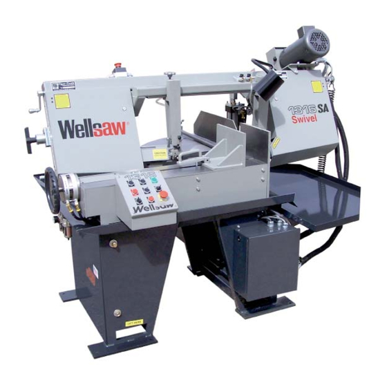
1 316S-SA
Parts List
Semi Automatic Bandsaw
with Swivel Head Feature
and
Built better to work stronger and last longer
Operating & Maintenance Manual
REV 170607
2829 N. Burdick St. Kalamazoo, MI 49004
Burdick St. Kalamazoo, MI 49004
Phone: 269-345-1132 Fax: 269-345-0095
269-345-1132 Fax: 269-345-0095
www.wellsaw.com
Advertisement
Table of Contents

Subscribe to Our Youtube Channel
Related Manuals for Wellsaw 1316S-SA


Summary of Contents for Wellsaw 1316S-SA
-
Page 1: Parts List
Semi Automatic Bandsaw with Swivel Head Feature Built better to work stronger and last longer Operating & Maintenance Manual REV 170607 2829 N. Burdick St. Kalamazoo, MI 49004 Burdick St. Kalamazoo, MI 49004 Phone: 269-345-1132 Fax: 269-345-0095 269-345-1132 Fax: 269-345-0095 www.wellsaw.com... -
Page 3: Table Of Contents
Table of Contents 1316S-SA Specifi cations ............. 3 Downfeed Assembly ............23 1316S-SA Components ............3 Blade Tension Mechanism ..........30 Safety Warning ..............6 Blade Brush Assembly ............34 Set up and Operation ............12 Valve & Manifold Detail .............24 Frame Assembly ..............14 Motor &... - Page 4 WELLSAW which our examination discloses to be defective because of workmanship or a defect in the material. This warranty does not apply if this WELLSAW has been used in a manner not consistent with its’...
- Page 5 Safety Instructions Always wear protective eye wear when operating machinery. 15. Use the right tool. Don’t force a tool or attachment to do a job Eye wear shall be impact resistant, protective safety glasses it was not designed for. with side shields which comply with ANSI Z87.1 specifi cations. 16.
-
Page 6: Safety Warning
Read and follow these simple rules for best results and full ben- accidents. efi ts from your machine. Used properly, WELLSAW’s machinery is among the best in design and safety. However, any machine AVOID DANGEROUS ENVIRONMENT. Do not use power tools in used improperly can be rendered ineffi... -
Page 7: Trouble Shooting
Notes on Sawing Trouble Shooting It is widely recognized that a proficient operator is a key to optimum bandsawing. He makes certain the Premature Dulling of Blade Teeth machine is properly maintained and adjusted for dependable operation. He carefully sets up each 1. - Page 8 6. Blade guides loose, worn or out of alignment. Premature Blade Breakage 7. Too many teeth-per-inch. Blade not cutting freely. 8. Chip brush not cleaning teeth properly. 1. Poor weld in the blade. 2. Feed rate set too high. Reduce it. 9.
- Page 9 the two cap screws opposite the outside end of the PLACING THE BLADE ON SAW wheel plate one-half turn. Tighten the two set Raise saw frame part way. screws on the same end one-half turn. Repeat if Open idle and drive wheel guards. necessary.
- Page 10 Fixed Vise Jaw Blade Guide Adjustment The two pins in the fixed vise jaw should be kept in To properly align the saw blade for a straight place in order to ensure square cuts. For cutting and accurate cut, do the following: angles, the pins must be removed and the turned to the desired position and tightened with clamp bolts.
- Page 11 3. Viscosity: Heavy Grease, drop point 219EC. Correct and adequate lubrication is a very 4. Military Specification: None. important factor in determining the life and service of your Wellsaw. It is essential that all dust, dirt, chips, etc. be Operation of the Swivel Feature for...
-
Page 12: Set Up And Operation
1316S SA Semi Automatic Bandsaw Set up and Operation Items needed: Electrical power 7 gallons of water Compressed air, 5 CFM @ 100 PSI Air tool oil for air lubricator. Prior to start up Warning! Do not lift saw frame with your hand! Saw frame is raised with a powered system. The saw should be placed on a level surface. - Page 13 Press the Blade Start button and adjust the desired band speed (250 SFPM for mild steels.) Make this adjustment only with motor running. Open the Coolant valves and note coolant flow to the blade. Slowly adjust coolant flow to the Idle End blade guide so that coolant just hangs off of the blade. Adjust coolant flow to the Drive End almost full open.
-
Page 14: Frame Assembly
Frame Assembly 70 22 29 33... - Page 15 Frame Assembly 1 150146SERV Idle Wheel Guard 2 150147SERV Drive Wheel Guard 42 100034-005 Set Screw, 5/16-18 x 3/4 3 100013-005 Machine Screw, BH 10-32 x 3/8 43 100004-015 Capscrew, HH 5/16-18 x 3/4 4 100024-002 Wing Nut, 1/4-20 44 100165-011 Shoulder Bolt, 3/8-16 x 1-1/2 5 100025-003 Lockwasher, 3/8 Blade Brush Ass'y.
-
Page 16: Bed Assembly
BED ASSEMBLY... - Page 17 BED ASSEMBLY...
-
Page 18: Table Assembly
Table Assembly and Cylinder TABLE ASSEMBLY... - Page 19 Table Assembly and Cylinder TABLE ASSEMBLY...
-
Page 20: Base Assembly
Base Assembly Base Assembly BASE ASSEMBLY... - Page 21 BASE ASSEMBLY...
-
Page 22: Coolant System
2 100220-070 Coolant Hose from Pan 166” 3 150066 Coolant Tank w/ fi lter 4 100350-040 Coolant Hose, I.E. 1/4” x 40” for 1316S-SA 100350-068 Coolant Hose, I.E. 1/4” x 68” for 1316S-SA-EXT 5 100324-003 Hose Barb, 1/4” 6 100226-004... -
Page 23: Downfeed Assembly
Down Feed Assembly... -
Page 24: Cylinder Assembly
Cylinder Assembly Cylinder Assembly Flow Control Flow Control FLOW CONTROL RESERVOIR ASSEMBLY Manifold Assembly Manifold Assembly MANIFOLD ASSEMBLY... - Page 25 Flow Control Flow Control Cylinder Assembly Cylinder Assembly Manifold Assembly Manifold Assembly MANIFOLD ASSEMBLY...
-
Page 26: Blade Guide Assembly
For Serial Numbers between 6090 and 6272 Blade Guides for 1" Blades 35 31 37 24 M1316BladeGuides-2... - Page 27 Blade Guides For serial #'s between 6090 and 6272. Serial numbers before for 1" Blade and after, use single bearings 100416-001 (SEE NEXT PAGE) 1 152158-003 Blade Guide Ass'y, D.E. between 6090 and 6272 (includes items 5 - 31& 35 - 37, minus 7,12,& 28) 152158-005 Blade Guide Assy, D.E.
- Page 28 BLADE GUIDES for 1" BLADES (BEFORE SN 6090 AND AFTER 6272)
- Page 29 BLADE GUIDES for 1" BLADES (BEFORE SN 6090 AND AFTER 6272)
-
Page 30: Blade Tension Mechanism
Rite Tensioning Device® Calibrating the WELLSAW RITE-TENSION ® Blade Tensioning Device The Rite-Tension® device is a simple turn counter that is activated by blade tension and can be easily adjusted in the field. Please review the operation instructions before making any adjustment: 1. - Page 31 Rite Tensioning Device® Caution: The Rite Tension ® blade tensiong device has been factory calibrated for your saw. When re-tightening or replacing a blade, the 'T' handle must be turned counter-clockwise at least six turns to reset the Rite Tension ® mechenism. 1 150075 Blade Tensioning Ass'y (includes items 2 thru 17 and 27)
-
Page 32: Motor & Gearbox
Motor & Gear Box 44 32 M1316MotorGearBox-2... - Page 33 Motor & Gear Box 1 100835-037 Motor, 3 HP TEFC, 3/4" shaft 3 phase - for s/n before 6559, need new pulley -021 too. 100836-031 Motor, 2 HP, 115-220/60/1 2 100056-037 3 150250 Belt Guard, Bottom Plate 4 105451-008 VS Motor Pulley, 7/8" bore, 3 Ph old style (before s/n 6559) 105451-021 VS Motor Pulley, 3/4"...
-
Page 34: Blade Brush Assembly
Blade Brush Assembly Note: Adjust thumb screw (11) so that the brush makes light contact with the blade. This avoids dulling the blade and prevents premature brush wear. 100165-007 Shoulder bolt, 3/8 x 3/8 18 100416-001 Bearing 100004-018 Cap Screw, HH 5/16-18 x 1 19 B-043 Axle 100025-002... -
Page 35: Control Panel
Control Panel... -
Page 36: Electrical Panel Components
ELECTRIC PANEL COMPONENTS (SN 8030 & LATER) -
Page 37: Electrical Schematic
Electrical Schematic 100781-011... -
Page 38: Feed And Speed Chart
Stock Dimensions 0 - 1" 1" - 3" 3" - 6" 6"+ Tooth Pitch 10/14, 8/12 8/12, 6/10, 5/8 5/8, 4/6, 3/4, 3 Sabre 3/4, 2/3, 2 Sabre, 1 Tooth, 3/4" T.S. Material (Annealed) Blade Cutting Blade Cutting Blade Cutting Blade Cutting Speed... - Page 39 Stock Dimensions 0 - 1" 1" - 3" 3" - 6" 6"+ Tooth Pitch 10/14, 8/12 8/12, 6/10, 5/8 5/8, 4/6, 3/4, 3 Sabre 3/4, 2/3, 2 Sabre, 1 Tooth, 3/4" T.S. Material (Annealed) Blade Cutting Blade Cutting Blade Cutting Blade Cutting Speed...
- Page 40 The Original..Since 1926 2829 N. Burdick St. Kalamazoo, MI 49004 Phone: 269-345-1132 Fax: 269-345-0095 website: www.wellsaw.com email: parts@wellsaw.com...
Need help?
Do you have a question about the 1316S-SA and is the answer not in the manual?
Questions and answers