Table of Contents
Advertisement
Quick Links
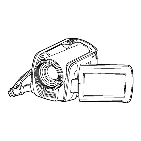
SD Card/Hard Disk Video Camera
SDR-H20E
SDR-H20EB
SDR-H20EE
SDR-H20EF
SDR-H20EG
SDR-H20EP
SDR-H20GC
SDR-H20GN
SDR-H21EE
SDR-H21GC
SDR-H28GK
SDR-H29GK
Vol. 1
Colours
(S)...................Silver Type
© 2007 Matsushita Electric Industrial Co., Ltd. All
rights
reserved.
distribution is a violation of law.
ORDER NO. VM0703038CE
Unauthorized
copying
and
Advertisement
Table of Contents


Need help?
Do you have a question about the SDR-H20EE and is the answer not in the manual?
Questions and answers