Sign In
Upload
Download
Table of Contents
Contents
Add to my manuals
Delete from my manuals
Share
URL of this page:
HTML Link:
Bookmark this page
Add
Manual will be automatically added to "My Manuals"
Print this page
×
Bookmark added
×
Added to my manuals
Manuals
Brands
Fluid Gaming Manuals
Computer Accessories
A120
User manual
Fluid Gaming A120 User Manual
Started liquid cooling kit
Hide thumbs
Also See for A120
:
User manual
(38 pages)
1
2
3
Table Of Contents
4
5
6
7
8
9
10
11
12
13
14
15
16
17
18
19
20
21
22
23
24
25
26
27
28
29
30
31
32
33
34
35
36
page
of
36
Go
/
36
Contents
Table of Contents
Troubleshooting
Bookmarks
Table of Contents
Safety Precautions
Table of Contents
Scope of Delivery
Required Tools
Radiator Space Constraint Requirements
Dozen Good Advices for the Newcomers
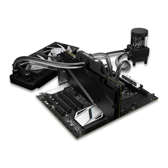
Liquid Cooling System
General Information on Water Block Compatibility
Installing the Water Block
Lga-2011(-3) Socket Motherboards
Lga-115X Socket Motherboards
Amd® Socket Am4 Motherboards
Installing the Radiator and Fans
Installing the Radiator and Fans in One Go
Installing the Pump-Reservoir Unit
Installing the Gpu Waterblocks
Connecting the Tubing
Electrical Connections
Connecting the Pump-Reservoir Unit
Connecting the Fans
Recommended Filling and Leak-Testing Procedure
Filling the System for the First Time
Draining of the Loop
Frequently Asked Questions
Troubleshooting
The Cooler Is too Loud
General Liquid Cooling Parts Cleaning Guide
Preventive Steps
Support and Service
Social Media
Advertisement
Quick Links
1
Installing the Water Block
2
Amd® Socket Am4 Motherboards
3
Installing the Gpu Waterblocks
4
Connecting the Tubing
5
Draining of the Loop
Download this manual
For EK-KIT A series units | 1st Revision, Apr 3rd 2017
Starter Liquid Cooling Kit
FLUID GAMING A120 A240 A240G
USER GUIDE
Table of
Contents
Previous
Page
Next
Page
1
2
3
4
5
Advertisement
Table of Contents
Need help?
Do you have a question about the A120 and is the answer not in the manual?
Ask a question
Questions and answers
Related Manuals for Fluid Gaming A120
Computer Accessories Fluid Gaming A240R User Manual
Starter liquid cooling kit (38 pages)
Computer Accessories Fluid Gaming A240G User Manual
Started liquid cooling kit (36 pages)
Computer Accessories Fluid Gaming A360G User Manual
Starter liquid cooling kit (38 pages)
Computer Accessories Fluid Gaming EK-AC Radeon RX 6700 XT D-RGB + Backplate User Manual
(16 pages)
This manual is also suitable for:
A240
A240g
Table of Contents
Print
Rename the bookmark
Delete bookmark?
Delete from my manuals?
Login
Sign In
OR
Sign in with Facebook
Sign in with Google
Upload manual
Upload from disk
Upload from URL


Need help?
Do you have a question about the A120 and is the answer not in the manual?
Questions and answers