Sign In
Upload
Download
Table of Contents
Contents
Add to my manuals
Delete from my manuals
Share
URL of this page:
HTML Link:
Bookmark this page
Add
Manual will be automatically added to "My Manuals"
Print this page
×
Bookmark added
×
Added to my manuals
Manuals
Brands
Loctite Manuals
Control Unit
97135
Operation manual
Loctite 97135 Operation Manual
Diaphragm valve
Hide thumbs
1
Table Of Contents
2
3
4
5
6
7
8
9
10
11
12
13
14
15
16
page
of
16
Go
/
16
Contents
Table of Contents
Troubleshooting
Bookmarks
Table of Contents
Table of Contents
1 Please Observe the Following
Emphasized Sections
Items Supplied
Field of Application (Intended Usage)
2 Description
For Your Safety
Operating Elements and Connections
3 Technical Data
Theory of Operation
Connecting to the Product Reservoir
4 Installation
Connecting to the Controller
5 Dispensing
Adjusting the Dispensed Quantity
Priming the Diaphragm Valve
Returning to Operation
Shutdown
Upgrading the Feed Line/Fitting
6 Care, Cleaning, and Maintenance
Cleaning
Maintenance
Disassembly
Assembly
Care, Cleaning, and Maintenance
7 Troubleshooting
8 Annex
Accessories and Spare Parts
Manufacturer's Declaration
9 Warranty (Excluding Germany)
Advertisement
Quick Links
1
Accessories and Spare Parts
Download this manual
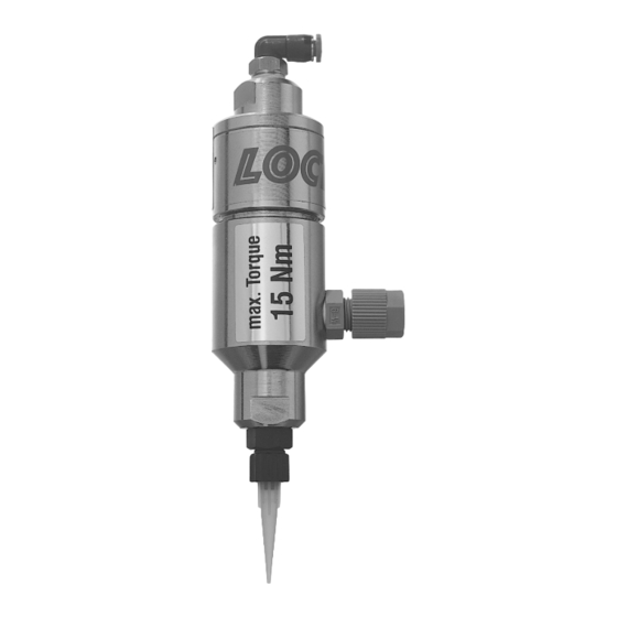
Loctite
®
Diaphragm Valve
Part Numbers 97135/97136
EQUIPMENT
Operation Manual
Table of
Contents
Previous
Page
Next
Page
1
2
3
4
5
Advertisement
Table of Contents
Need help?
Do you have a question about the 97135 and is the answer not in the manual?
Ask a question
Questions and answers
Related Manuals for Loctite 97135
Control Unit Loctite 97136 Operation Manual
Diaphragm valve (16 pages)
Control Unit Loctite 97121 Operating Manual
Pinch valve (47 pages)
Control Unit Loctite 97111 Operation Manual
Hand-held applicator, global availability, global service (21 pages)
Control Unit Loctite 97112 Operation Manual
Hand-held applicator, global availability, global service (21 pages)
Control Unit Loctite 97116 Operation Manual
Hand-held applicator, global availability, global service (21 pages)
Control Unit Loctite 98084 Operation Manual
Micro needle valve (12 pages)
Control Unit Loctite 986326 Instruction Sheet
(2 pages)
This manual is also suitable for:
97136
Table of Contents
Print
Rename the bookmark
Delete bookmark?
Delete from my manuals?
Login
Sign In
OR
Sign in with Facebook
Sign in with Google
Upload manual
Upload from disk
Upload from URL


Need help?
Do you have a question about the 97135 and is the answer not in the manual?
Questions and answers