
Related Manuals for CCE HPS-141


Summary of Contents for CCE HPS-141
-
Page 1: Service Manual
Service Manual Model HPS-141 CCE da Amazônia CCE CODE: 1.01.73019.51 __________________________ Assinatura de Aprovação Approved Assignature... -
Page 2: Table Of Contents
HPS-141 INDEX GENERAL................................... 2 PRODUCT FRONT VIEW ............................. 2 PRODUCT BACK VIEW............................2 REMOTE CONTROL............................... 4 TECHNICAL SPECIFICATION........................... 5 AUDIO ..................................5 POWER SUPPLY..............................9 FRAME GEOMETRIC............................12 PURITY..................................18 CONVERGENCE..............................19 VIDEO..................................20 CALIBRATION GUIDE ............................22 IMPORTANT RECOMMENDATIONS ......................22 DEFINITIONS OF THE REGISTERS ......................23 GEOMETRY OF THE IMAGE..........................25... -
Page 3: General
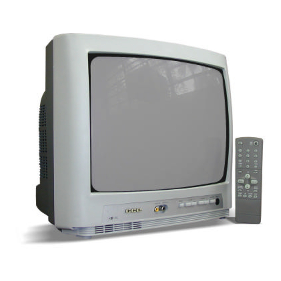
HPS-141 GENERAL 1.1 Product Front View a) Frontal Panel a.1) Front Panel Functions and Indications Video Input Channel Audio Input Channel Menu Power On/Off Remote Control Sensor Volume Volume Product Back View Back panel a.1) Back Panel Functions and Indications... - Page 4 HPS-141 b) Characteristic Image Sound Menu Functions Functions Install Channel from 2 to 13 Channel Channel from 14 to 69 Cable TV Channel from 1 to 125 Dimensions 347 x 320 x 360 mm Weight 8, 4 kg c) Supply...
-
Page 5: Remote Control
HPS-141 1.3 REMOTE CONTROL a.1) Remote Control Functions Power - On/Off Sleep Keyboard key P. Channel Timer OSD / OUT CC – Close caption ∧ ∧ < < Channel Volume > > Menu Volume ∨ ∨ P. Skip Channel Auto Image... -
Page 6: Technical Specification
HPS-141 2. TECHNICAL SPECIFICATION Procedure to check up color TV electrical parameters Audio 2.1.1 Output power at 10% THD method: antenna input connection a) TV setup in “PP” condition (frequency and channel factory defined) b) Apply 60dB µV signal to antenna input, modulated with white pattern in 88% and audio signal with 1kHz frequency modulated in FM with ±... - Page 7 HPS-141 2.1.2 Audio Residual a) TV setup in “PP” condition. b) Apply 60dB µV signal (frequency and channel factory defined) to antenna input modulated with white pattern at 88% and audio signal with 1kHz frequency modulated in FM with 25kHz deviation.
- Page 8 HPS-141 2.1.4 Áudio frequency response for the stereo television set with tonality control a) Repeat the above procedures (item 1.3) for the following additional conditions: Condition Minimum Nominal Maximum Unit Bass control in max. position 100Hz Treble control in the meddle.
- Page 9 HPS-141 2.1.6 Output and distortion level of S.A.P. signal for the stereo television set. a) TV setup in PP condition. b) Apply a 60dB µV signal ( Frequency and channel factory defined ) with 88% video modulation, and Stereo / S.A.P audio signal carrier in accordance of standard “MTS”...
-
Page 10: Power Supply
HPS-141 POWER SUPPLY 2.2.1 Consume Consume a) Connect the TV under test through a electronic wattmeter at the 234Vac/60Hz line. b) Turn-on the TV set and apply a 60dBµV ( the preferred channel must to be defined by the production unit), modulated with a 88% video signal white pattern, and a ± 25 kHz deviation FM carrier with a 1kHz sine wave audio signal. - Page 11 HPS-141 2.2.3 Main Power Supply Regulation with fluctuation of the line a) Repeat the procedure of the item 2.2 when the television is connected to the electric net with 100VAC/60Hz and also 240VAC/60Hz. Condition Test Point Minimum Nominal Maximum Unit “PP”...
- Page 12 HPS-141 2.2.5 High Voltage (EHT) a) Connect a DC voltmeter to the resistor wired to the Fly Back ABL pin ( the position and value of this resist is defined by each model. b) Connect a high voltage electronic DC voltmeter ( over 1G impedance) in the electronic tube high voltage plug.
-
Page 13: Frame Geometric
HPS-141 Frame geometric 2.3.1 Wide and height of the frame Preparation: a) Connect the receiver under test to a 117V line. b) TV setup in PP condition. c) Apply to the antenna input a 60dB µV signal – 88% modulated with the CROSSHATCH... - Page 14 HPS-141 2.3.2 Frame centralization Preparation: a) Connect the receiver under test to a 117 V line. Turn On the TV and position the bright and contrast control to the maximum, and the saturation and volume controls to the minimum position. Wait for a pre-heating period.
- Page 15 HPS-141 2.3.3 FRAME ASPECT RELATED a) Connect the receiver under test to a 117V line. Turn on the TV and adjust bright and contrast control to max. position, saturation and volume to min. Position. Wait for the heat period. b) Apply to the antenna input a 60dB µV level signal with 88% modulated PHILIPS pattern...
- Page 16 HPS-141 2.3.4 Horizontal Linearity a) Connect the receiver under test in 117V line. Turn on the TV and adjust bright and contrast control to max. position, saturation and volume to min. Position. Wait for the heat period. b) Apply to the antenna input a 60dB µV level signal with 88% modulated PHILIPS pattern...
- Page 17 HPS-141 2.3.5 Vertical Linearity a) Connect the receiver to a 117V line Turn on the TV and adjust bright and contrast control to max. position, saturation and volume to min. Position. Wait for the heat period (please see the specification for this model).
- Page 18 HPS-141 2.3.6 Pin-Cushion & Shape of Raster a) Connect the receiver to a 117V line. Turn on the TV and adjust bright and contrast control to max. position, saturation and volume to min. Position. Wait for the heat period (please see the specification for this model).
-
Page 19: Purity
HPS-141 Purity a) Connect the receiver to a 117V line Turn on the TV and adjust bright to nominal position and contrast control to min. position, saturation and volume to min. position. b) Apply to the antenna input a 60dB µV level signal with 88% modulated “WHITE” pattern... -
Page 20: Convergence
HPS-141 Convergence a) Connect the receiver to a 117V line Turn on the TV and adjust bright and contrast control to max.. position, saturation and volume to min. position. Wait for pre-heating period ( please see specification for each model) b) Apply to the antenna input a 60dB µV level signal with 88% modulated “CROSSHATCH”... -
Page 21: Video
HPS-141 Video 2.6.1 Sensibility and Signal /Noise Rate a) Adjust the TV to a “PP” condition. b) Apply to the antenna input a 60dB µV signal with 60% AM modulation, 1kHz sine wave (Frequency and channel factory defined). c) Connect at the output video detector na AC voltmeter and read the voltage V d) Turn off the AM modulation and read the noise level “Vr”... - Page 22 HPS-141 2.6.4 Vertical sensitivity a) Adjust the TV to a “PP” condition. b) Apply to the antenna input a 60dB µV signal with 88% AM modulation with PAL-M color pattern (Frequency and channel factory defined), and FM sine wave 1kHz audio modulation +-25 kHz deviation.
-
Page 23: Calibration Guide
HPS-141 3. CALIBRATION GUIDE Note: This guide is only an orientation and, for some items, may be adapted by Factory Engineering to best conform to the productive process. INTRODUCTION Note: ü It is necessary to pre-heat the TV during 15 minutes, before its calibration. -
Page 24: Definitions Of The Registers
HPS-141 Definitions of the registers Description of service and factory registers Register Name Range Description Default Value 63 Horizontal shift 00 Vertical screen 63 Vertical slope 63 Vertical amplitude 63 Vertical shift 63 S-correction The registers bellow must be set to the default values. - Page 25 HPS-141 The registers bellow must be set to the default values. Register Name Range Description Default Value 63 Hue 63 Volume STNT 15 Stereo noise threshold SPNT 15 SAP noise threshold 15 Input level adjustment 31 Alignment for wideband 31 Alignment for spectral Please, look the functions of registers bellow, before of change to the default value.
-
Page 26: Geometry Of The Image
HPS-141 Geometry of the Image a) Using the PM - 5515 generator, apply the crosshatch pattern with circle. b) Adjust the bellow items, until obtaining the best circle symmetry and positioning, as well as the minor image geometric distortion: ü ü Use the register (VSl) to adjust the Vertical slope;... -
Page 27: Screen Adjustment
HPS-141 Screen adjustment Mode 1: a) Apply a gray scale pattern. b) Adjust the controls to: ü ü Brightness - 50% ü ü Contrast - 70% c) Measure DC voltage on the three cathodes (CRT) (one at a time) and select the highest one. -
Page 28: Material List
HPS-141 MATERIAL LIST 4.1 MAIN PCB CAPACITORS CODE DESCRIPTION POSITION 1339273103 C.POLYMET 27KPF/63V J MINIBLUE C809 1330273103 C.POLYMET 27KPF/63V J C809 1339104106 C.POLYM.100KPF/63V K MINI BLUE C636 1339104421 C.POLYM.100KPF/250V J MINIBLUE C411 1339224222 C.POLYM. 220KPF/100V K MINIBLU C303 1339332100 C.POLYMET 3,3KPF/63V K MINIBLU... - Page 29 HPS-141 CODE DESCRIPTION POSITION 1380101328 ELCO 100UF/25V M 6,3X11MM C107 1380101328 ELCO 100UF/25V M 6,3X11MM C834 1380101328 ELCO 100UF/25V M 6,3X11MM C836 1380101328 ELCO 100UF/25V M 6,3X11MM C839 1380101328 ELCO 100UF/25V M 6,3X11MM C851 1380101630 ELCO 100UF/35V M 6,3X11 C302...
- Page 30 HPS-141 CODE DESCRIPTION POSITION 1492010200 CAP.SMD X7R 1KPF/50V K 0603 C306 1492010200 CAP.SMD X7R 1KPF/50V K 0603 C648 1492010200 CAP.SMD X7R 1KPF/50V K 0603 C714 1492010200 CAP.SMD X7R 1KPF/50V K 0603 C771 1492010300 CAP.SMD X7R 10KPF/50V K 0603 C105 1492010300 CAP.SMD X7R 10KPF/50V K 0603...
- Page 31 HPS-141 CODE DESCRIPTION POSITION 1363102300 C.C.D. Y5P 1KPF>= 50V K C822 1380470921 ELCO 47uF/160V M 12,5x25mm HR C825 RESISTORS CODE DESCRIPTION POSITION 1183510092 RES.METAL FILME 1/2W 10R 5% N R826 1183510192 RES.METAL FILME 1/2W 100R 5% N R302 1183510192 RES.METAL FILME 1/2W 100R 5% N...
- Page 32 HPS-141 CODE DESCRIPTION POSITION 1183539392 RES.METAL FILME 1/2W 39K 5% N R415 1183547292 RES.METAL FILME 1/2W 4,7K 5% N R215 1183547292 RES.METAL FILME 1/2W 4,7K 5% N R722 1183547392 RES.METAL.FILME 1/2W 47K 5% N R208 1183547392 RES.METAL.FILME 1/2W 47K 5% N...
- Page 33 HPS-141 CODE DESCRIPTION POSITION 1502539203 * RES.SMD 3,9K 5% 0603 R601 1183547092 RES.METAL FILME 1/2W 47R 5% N R706 1502547103 * RES.SMD 470R 5% 0603 R779 1502547203 * RES.SMD 4,7K 5% 0603 R704 1502547203 * RES.SMD 4,7K 5% 0603 R723 1502547903 * RES.SMD 4,7R 5% 0603...
- Page 34 HPS-141 CODE DESCRIPTION POSITION 1414621902 * DIODO 1N4148 75V SINAL D406 1414621902 * DIODO 1N4148 75V SINAL D407 1414621902 * DIODO 1N4148 75V SINAL D408 1414621902 * DIODO 1N4148 75V SINAL D701 1414621902 * DIODO 1N4148 75V SINAL D801 1414621902...
- Page 35 HPS-141 TRANSISTORS AND IC´s CODE DESCRIPTION POSITION 1320030102 * TRANSISTOR BC337/16 Q101 1320030102 * TRANSISTOR BC337/16 Q802 1320030102 * TRANSISTOR BC337/16 Q803 1320030102 * TRANSISTOR BC337/16 Q804 1320090500 * TRANSISTOR BF422 Q901 1320090500 * TRANSISTOR BF422 Q903 1320090500 * TRANSISTOR BF422...
- Page 36 HPS-141 CODE DESCRIPTION POSITION 1479907634 * INDUTOR FIXO 5,6UH K AXIAL L705 1479907634 * INDUTOR FIXO 5,6UH K AXIAL L706 1479907634 * INDUTOR FIXO 5,6UH K AXIAL L707 1479907634 * INDUTOR FIXO 5,6UH K AXIAL L801 1479908234 * INDUTOR FIXO 10UH K AXIAL...
- Page 37 HPS-141 CODE DESCRIPTION POSITION 1312401100 FILTRO DE LINHA ELF412 LF801 1422010199 * FILTRO DE LINHA SS24H-K18055 LF801 1359307504 BOBINA MOVEL 1/2"KP-8-10/2C 1359307504 BOBINA MOVEL 1/2"KP-8-10/2C TRAFO AND CRISTAL CODE DESCRIPTION POSITION 1353002400 TRAFO DRIVE TD-14 T401 1355218599 TRAFO FLY BACK TAT-1412A...
- Page 38 HPS-141 CODE DESCRIPTION POSITION 1777205902 ESPACADOR 1057301999 CJ.CALCO PROTETOR ESQ./DIREITO 1769900122 SACO PLATICO 250X400X0,05 AD 1769900119 SACO PLASTICO 720X750X0,05 AD 1738002200 MALHA DE ATERRAMENTO 1682021400 MOLA DE ATERRAMENTO DO CRT 1159960000 TUBO TERMOCONTRATIL D=7,9MM PR 1850473402 FILME POLIET.B.D.E=0,06XL=620 EMBAL. 1600005508 PAR.AA.PAN.PH.PP1 3,0X12 ZNP...
- Page 39 HPS-141 CODE DESCRIPTION POSITION 1876307460 ADESIVO PVA 045 1880500900 SOLDA TRIFLUXO 60X40X1,5MM 1876305300 ADESIVO BASE BORRACHA PR 1779407501 PROTETOR ENCAIXE 240FR 1779507500 GUARNICAO AF3 1876307460 ADESIVO PVA 045 1876307460 ADESIVO PVA 045 1876309300 ADESIVO ATIVADOR 1427600755 IMA 32X18X5MM 1876304900 ADESIVO ESTRUTURAL 3925 AZ...
- Page 40 TABULEIRO SPS 625X375 1771080400 CAIXA PLASTICA DOBRAVEL 1889401000 FITA ADES S/LOG L=50MM C=100MT 1644507400 CABO DE FORCA 2X0,75X2000MM PP CF801 1067301901 MANUAL DE INSTRUCOES HPS-141 1069100070 FOLHETO OFICINAS AUTORIZADAS 1069100069 FOLHETO OFICINAS AUTORIZADAS 1069100066 CERTIFICADO DE GARANTIA 4.1 REMOTE CONTROL PCB CODE...
- Page 41 HPS-141 CODE DESCRIPTION POSITION 1769900049 SACO PLASTICO 7X23X0,05 1311604900 BOBINA DESMAGNETIZADORA BOB801...
-
Page 42: Electrical Scheme
HPS-141 5. ELECTRICAL SCHEME 5.1 MAIN AND REMOTE CONTROL PCB 6. SILKTOP AND SOLDERS 6.1 MAIN PCB 6.2 REMOTE CONTROL PCB 7. EXPLODED VIEW 488. BOCK DIAGRAM... - Page 43 1271205200 1271205200 RM701 RM701 SPARK SPARK 36KHz 36KHz 1271505000 1271505000 1633219400 1633219400 TU101 TU101 +33V +33V IC601 IC601 AUDIO AUDIO AUDIO AUDIO C703 C703 TDA1013B TDA1013B 47uF/25V 47uF/25V REMOT REMOT 1380470324 1380470324 1149379299 1149379299 R706 R706 1183547092 1183547092 1184515325 1184515325 R101 R101 1633208360...
- Page 44 R702 DZ702 R709 R113 CN601 C107 D101 DZ102 PROJEÇÃO PROJEÇÃO PCI PRINCIPAL PCI PRINCIPAL TÍTULO TÍTULO dimensões em mm dimensões em mm NOME NOME DATA DATA MAT. MAT. ROBERTO ROBERTO 15/08/00 15/08/00 HPS-141 HPS-141 MOD. MOD. N.º N.º APROV. APROV.
- Page 45 C631 R610 R704 R214 C710 R104 C633 R616 PROJEÇÃO PROJEÇÃO PCI PRINCIPAL PCI PRINCIPAL TÍTULO TÍTULO dimensões em mm dimensões em mm NOME NOME DATA DATA MAT. MAT. ROBERTO ROBERTO 15/08/00 15/08/00 HPS-141 HPS-141 MOD. MOD. N.º N.º APROV. APROV.
- Page 46 MUTE SKIP OSD/ MENU SAIR VOL+ VOL- AUTO AUTO TIMER ST/SAP SLEEP SLEEP ST/SAP PROJEÇÃO TÍTULO: REMOTE CONTROL PCB dimensões em mm NOME DATA MAT. DES. PERES 15/08/00 ACAB. 15/08/00 ESC. TOL. PROJ. ROSÁRIO N.º 15/08/00 HPS-141 APRO. WALTER MOD.
- Page 47 PROJEÇÃO TÍTULO: REMOTE CONTROL PCB dimensões em mm NOME DATA MAT. DES. PERES 15/08/00 ACAB. 15/08/00 ESC. TOL. PROJ. ROSÁRIO N.º 15/08/00 HPS-141 APRO. WALTER MOD.
- Page 49 IC601 TDA1013B TU101 TUNER AUDIO OUTPUT IC301 TDA9309 IR RC SENSOR VERTICAL OUTPUT VERTICAL DEFLECTION CURRENT IC101 AUDIO / VIDEO TDA9570H AUX INPUT µCONTROLLER V901 IF PROCESSOR I²C BUS Y/C PROCESSOR SYNC PROCESSOR AUDIO PROCESSOR +12V IC701 -12V BR24C08/F EEPROM +15V SMPS HORIZONTAL...
Need help?
Do you have a question about the HPS-141 and is the answer not in the manual?
Questions and answers