Table of Contents
Advertisement
Advertisement
Table of Contents

Related Manuals for CCE HPS-2007


Summary of Contents for CCE HPS-2007
-
Page 1: Service Manual
Service Manual Model HPS-2007 CCE CODE: 1.01.72337.59... -
Page 2: Table Of Contents
HPS-2007 INDEX GENERAL.........................2 PRODUCT FRONT VIEW ..................2 PRODUCT BACK VIEW ..................2 REMOTE CONTROL ....................4 TECHNICAL SPECIFICATION ................5 AUDIO........................5 POWER SUPPLY....................9 FRAME GEOMETRIC...................12 PURITY........................18 CONVERGENCE....................19 VIDEO........................20 CALIBRATION GUIDE ..................22 IMPORTANT RECOMMENDATIONS..............22 DEFINITIONS OF THE REGISTERS..............23 GEOMETRY OF THE IMAGE................25 WHITE BALANCE....................25 SCREEN ADJUSTMENT..................26... -
Page 3: General
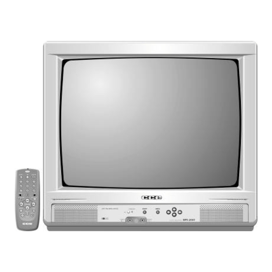
HPS-2007 GENERAL 1.1 Product front view a) Front panel a.1) Front panel functions and indications Remote control sensor Menu Video input Channel UP Standby Volume UP Audio input Channel DOWN Power On/Off Volume DOWN Product back view Back panel a.1) Back panel functions and indicatioins Antenna input - UHF/ VHF ( 75 Ω... - Page 4 HPS-2007 b) Characteristics Image Sound Menu of Functions Function Install Channel from 2 to 13 Channel Channel from 14 to 69 Cable TV Channel from 1 to 125 Product Dimensions 355X343X375 mm c) Supply Unit Nominal Min. Max. Supply Voltage (FREE VOLTAGE)
-
Page 5: Remote Control
HPS-2007 1.3 REMOTE CONTROL 1.3.1) Remote control fucntions Power - On/Off Sleep Numeric Keyborad key Timer CC - Closed Caption Channel + Auto Image Volume - Volume + P. Channel Channel - P. Skip OSD / OUT Mute Menu... -
Page 6: Technical Specification
HPS-2007 2. TECHNICAL SPECIFICATION Procedure to check up color TV electrical parameters Audio 2.1.1 Output power at 10% THD method: antenna input connection a) TV setup in “PP” condition (frequency and channel factory defined) b) Apply 60dB µV signal to antenna input, modulated with white pattern in 88% and audio signal with 1kHz frequency modulated in FM with ±... - Page 7 HPS-2007 2.1.2 Audio Residual a) TV setup in “PP” condition. b) Apply 60dB µV signal (frequency and channel factory defined) to antenna input modulated with white pattern at 88% and audio signal with 1kHz frequency modulated in FM with 25kHz deviation.
- Page 8 HPS-2007 2.1.4 Áudio frequency response for the stereo television set with tonality control a) Repeat the above procedures (item 1.3) for the following additional conditions: Condition Minimum Nominal Maximum Unit Bass control in max. position 100Hz Treble control in the meddle.
- Page 9 HPS-2007 2.1.6 Output and distortion level of S.A.P. signal for the stereo television set. a) TV setup in PP condition. b) Apply a 60dB µV signal ( Frequency and channel factory defined ) with 88% video modulation, and Stereo / S.A.P audio signal carrier in accordance of standard “MTS”...
-
Page 10: Power Supply
HPS-2007 POWER SUPPLY 2.2.1 Consume Consume a) Connect the TV under test through a electronic wattmeter at the 234Vac/60Hz line. b) Turn-on the TV set and apply a 60dBµV ( the preferred channel must to be defined by the production unit), modulated with a 88% video signal white pattern, and a ± 25 kHz deviation FM carrier with a 1kHz sine wave audio signal. - Page 11 HPS-2007 2.2.3 Main Power Supply Regulation with fluctuation of the line a) Repeat the procedure of the item 2.2 when the television is connected to the electric net with 100VAC/60Hz and also 240VAC/60Hz. Condition Test Point Minimum Nominal Maximum Unit “PP”...
- Page 12 HPS-2007 2.2.5 High Voltage (EHT) a) Connect a DC v oltmeter to the resistor wired to the Fly Back ABL pin ( the position and value of this resist is defined by each model. b) Connect a high voltage electronic DC voltmeter ( over 1G impedance) in the electronic tube high voltage plug.
-
Page 13: Frame Geometric
HPS-2007 Frame geometric 2.3.1 Wide and height of the frame Preparation: a) Connect the receiver under test to a 117V line. b) TV setup in PP condition. c) Apply to the antenna input a 60dB µV signal – 88% modulated with the CROSSHATCH... - Page 14 HPS-2007 2.3.2 Frame centralization Preparation: a) Connect the receiver under test to a 117 V line. Turn On the TV and position the bright and contrast control to the maximum, and the saturation and volume controls to the minimum position. Wait for a pre-heating period.
- Page 15 HPS-2007 2.3.3 FRAME ASPECT RELATED a) Connect the receiver under test to a 117V line. Turn on the TV and adjust bright and contrast control to max. position, saturation and volume to min. Position. Wait for the heat period. b) Apply to the antenna input a 60dB µV level signal with 88% modulated PHILIPS pattern...
- Page 16 HPS-2007 2.3.4 Horizontal Linearity a) Connect the receiver under test in 117V line. Turn on the TV and adjust bright and contrast control to max. position, saturation and volume to min. Position. Wait for the heat period. b) Apply to the antenna input a 60dB µV level signal with 88% modulated PHILIPS pattern...
- Page 17 HPS-2007 2.3.5 Vertical Linearity a) Connect the receiver to a 117V line Turn on the TV and adjust bright and contrast control to max. position, saturation and volume to min. Position. Wait for the heat period (please see the specification for this model).
- Page 18 HPS-2007 2.3.6 Pin-Cushion & Shape of Raster a) Connect the receiver to a 117V line. Turn on the TV and adjust bright and contrast control to max. position, saturation and volume to min. Position. Wait for the heat period (please see the specification for this model).
-
Page 19: Purity
HPS-2007 Purity a) Connect the receiver to a 117V line Turn on the TV and adjust bright to nominal position and contrast control to min. position, saturation and volume to min. position. b) Apply to the antenna input a 60dB µV level signal with 88% modulated “WHITE” pattern... -
Page 20: Convergence
HPS-2007 Convergence a) Connect the receiver to a 117V line Turn on the TV and adjust bright and contrast control to max.. position, saturation and volume to min. position. Wait for pre-heating period ( please see specification for each model) b) Apply to the antenna input a 60dB µV level signal with 88% modulated “CROSSHATCH”... -
Page 21: Video
HPS-2007 Video 2.6.1 Sensibility and Signal /Noise Rate a) Adjust the TV to a “PP” condition. b) Apply to the antenna input a 60dB µV signal with 60% AM modulation, 1kHz sine wave (Frequency and channel factory defined). c) Connect at the output video detector na AC voltmeter and read the voltage V d) Turn off the AM modulation and read the noise level “Vr”... - Page 22 HPS-2007 2.6.4 Vertical sensitivity a) Adjust the TV to a “PP” condition. b) Apply to the antenna input a 60dB µV signal with 88% AM modulation with PAL-M color pattern (Frequency and channel factory defined), and FM sine wave 1kHz audio modulation +-25 kHz deviation.
-
Page 23: Calibration Guide
HPS-2007 3. CALIBRATION GUIDE Note: This guide is only an orientation and, for some items, may be adapted by Factory Engineering to best conform to the productive process. INTRODUCTION Note: ü It is necessary to pre-heat the TV during 15 minutes, before its calibration. -
Page 24: Definitions Of The Registers
HPS-2007 Definitions of the registers Description of service and factory registers Register Name Range Description Default Value 63 Horizontal shift 00 Vertical screen 63 Vertical slope 63 Vertical amplitude 63 Vertical shift 63 S-correction The registers bellow must be set to the default values. - Page 25 HPS-2007 The registers bellow must be set to the default values. Register Name Range Description Default Value 63 Hue 63 Volume STNT 15 Stereo noise threshold SPNT 15 SAP noise threshold 15 Input level adjustment 31 Alignment for wideband 31 Alignment for spectral Please, look the functions of registers bellow, before of change to the default value.
-
Page 26: Geometry Of The Image
HPS-2007 Geometry of the Image a) Using the PM - 5515 generator, apply the crosshatch pattern with circle. b) Adjust the bellow items, until obtaining the best circle symmetry and positioning, as well as the minor image geometric distortion: ü Use the register (VSl) to adjust the Vertical slope;... -
Page 27: Screen Adjustment
HPS-2007 Screen adjustment Mode 1: a) Apply a gray scale pattern. b) Adjust the controls to: ü Brightness - 50% ü Contrast - 70% c) Measure DC voltage on the three cathodes (CRT) (one at a time) and select the highest one. -
Page 28: Material List
HPS-2007 4. MATERIAL LIST MAIN PCB CAPACITORS CODE DESCRIPTION POSITION 1330104106 C.POLYEMT 100KPF/63V K C636 1330104421 C.POLYMET 100KPF/250V J C411 1330224222 C.POLYMET 220KPF/100V K C303 1330273103 C.POLYMET 27KPF/63V J C809 1330473400 CAP. POLYMET MKT 47KPF/250V K C424 1330473521 C.POLYMET 47KPF/400V K... - Page 29 HPS-2007 CODE DESCRIPTION POSITION 1380100422 ELCO 10UF/50V K 5X11MM C718 1380100422 ELCO 10UF/50V K 5X11MM C742 1380100524 ELCO 10UF/50V M 5X11MM C104 1380100524 ELCO 10UF/50V M 5X11MM C201 1380100526 ELCO 10UF/16V M 5X11MM C201 1380100632 ELCO 10UF/35V M 5X11MM C201...
- Page 30 HPS-2007 CODE DESCRIPTION POSITION 1380479032 ELCO 4,7UF/250V M 10X12,5MM C423 1380479622 ELCO 4,7UF/100V M 5x11mm C207 1380479622 ELCO 4,7UF/100V M 5x11mm C406 1380479622 ELCO 4,7UF/100V M 5x11mm C806 1380479622 ELCO 4,7UF/100V M 5x11mm C807 1380479522 ELCO 4,7UF/50V M 5X11MM C207...
- Page 31 HPS-2007 CODE DESCRIPTION POSITION 1492010200 CAP.SMD X7R 1KPF/50V K 0603 C306 1492010200 CAP.SMD X7R 1KPF/50V K 0603 C648 1492010200 CAP.SMD X7R 1KPF/50V K 0603 C650 1492010200 CAP.SMD X7R 1KPF/50V K 0603 C714 1492010200 CAP.SMD X7R 1KPF/50V K 0603 C770 1492010200 CAP.SMD X7R 1KPF/50V K 0603...
- Page 32 HPS-2007 CODE DESCRIPTION POSITION 1494210410 CAP.SMD Y5P 100KPF/25V K 0805 C633 1494210410 CAP.SMD Y5P 100KPF/25V K 0805 C740 1492022300 CAP.SMD X7R 22KPF/25V K 0603 C205 1492022300 CAP.SMD X7R 22KPF/25V K 0603 C260 1492022300 CAP.SMD X7R 22KPF/25V K 0603 C560 1492022300 CAP.SMD X7R 22KPF/25V K 0603...
- Page 33 HPS-2007 CODE DESCRIPTION POSITION 1492012200 CAP.SMD X7R 1,2KPF/50V K 0603 C601 1490512200 CAP. SMD X7R 1,2KPF/50V K 0805 C601 1494212200 CAP.SMD Y5P 1,2KPF/50V K 0805 C601 1363331803 C.C.D. Y5P 330PF/2KV K 6LS C417 1331104004 CAP.POLYPRO 100KPF/160V 5% C301 1265104074 C.POLYPRO 100KPF/250VAC K X3...
- Page 34 HPS-2007 CODE DESCRIPTION POSITION 1183515992 RES.METAL FILME 1/2W 1,5R 5% N R306 1183518192 RES.METAL FILME 1/2W 180R 5% N R809 1183518292 RES.METAL FILME 1/2W 1,8K 5% N R614 1183518292 RES.METAL FILME 1/2W 1,8K 5% N R804 1183518292 RES.METAL FILME 1/2W 1,8K 5% N...
- Page 35 HPS-2007 CODE DESCRIPTION POSITION 1502510102 RES.SMD 100R 5% 0805 R566 1502510203 RES.SMD 1K 5% 0603 R201 1502510203 RES.SMD 1K 5% 0603 R705 1502510203 RES.SMD 1K 5% 0603 R775 1502510202 RES.SMD 1K 5% 0805 R201 1502510202 RES.SMD 1K 5% 0805 R705 1502510202 RES.SMD 1K 5% 0805...
- Page 36 HPS-2007 CODE DESCRIPTION POSITION 1502522203 RES.SMD 2,2K 5% 0603 R749 1502522202 RES.SMD 2,2K 5% 0805 R708 1502522202 RES.SMD 2,2K 5% 0805 R749 1502522303 RES.SMD 22K 5% 0603 R402 1502522303 RES.SMD 22K 5% 0603 R403 1502522303 RES.SMD 22K 5% 0603 R412 1502522303 RES.SMD 22K 5% 0603...
- Page 37 HPS-2007 CODE DESCRIPTION POSITION 1502582103 RES.SMD 820R 5% 0603 R711 1502582103 RES.SMD 820R 5% 0603 R780 1502582102 RES.SMD 820R 5% 0805 R406 1502582102 RES.SMD 820R 5% 0805 R711 1502582102 RES.SMD 820R 5% 0805 R780 1125707400 RES.COEF.NEG.NTC 10R NTC801 1125708800 RES.COEF.NEG.NTC.4R7...
- Page 38 HPS-2007 CODE DESCRIPTION POSITION 1183668519 RES.COMPOS.1/2W 6,8M K R815 1183615219 RES.COMPOS.1/2W 1,5K 5% N R910 1183615219 RES.COMPOS.1/2W 1,5K 5% N R919 1183615219 RES.COMPOS.1/2W 1,5K 5% N R928 SEMICONDUCTORS CODE DESCRIPTION POSITION 1320091000 TRANSISTOR BC337/25 Q101 1320091000 TRANSISTOR BC337/25 Q802 1320091000...
- Page 39 HPS-2007 CODE DESCRIPTION POSITION 1139999264 TRANSISTOR 2SD-1878 Q402 1139999301 TRANSISTOR BU-2508DX Q402 1139999468 TRANS.POWER MOSFET STP6NK90ZFP Q801 1139999458 TRANSISTOR FQPF6N80 Q801 1139999463 TRANS.POWER MOS-FET STF9NK90Z Q801 1415180801 DIODO RETIFICADOR SK 4F1/06 D401 1415180801 DIODO RETIFICADOR SK 4F1/06 D402 1415180801 DIODO RETIFICADOR SK 4F1/06...
- Page 40 HPS-2007 CODE DESCRIPTION POSITION 1415169401 DIODO ZENER BZX79C5V1 DZ102 1415169801 DIODO ZENER BZX79C8V2 DZ807 1415170901 DIODO ZENER BZX79C33V DZ101 1415171901 DIODO ZENER BZX79C18V DZ801 1415171901 DIODO ZENER BZX79C18V DZ802 1415180901 DIODO RETIFICADOR SK107 D301 1410430015 DIODO RETIFICADOR 1N4004 D301 1415172201...
- Page 41 HPS-2007 MISCELLANEOUS CODE DESCRIPTION POSITION 1027233737 PCI PRINCIPAL MANUAL 1027233734 PCI PRINCIPAL SMD 1027233736 PCI PRINCIPAL IA 1107225136 PCI PRINCIPAL 1479903734 INDUTOR FIXO 22UH K AXIAL L102 1479906734 INDUTOR FIXO 2,2UH K AXIAL L703 1479906734 INDUTOR FIXO 2,2UH K AXIAL...
- Page 42 HPS-2007 CODE DESCRIPTION POSITION 1271505500 SINTONIZADOR 181CH TEDH9-301A TU101 1312400100 FILTRO DE LINHA LF801 1319959400 INDUTOR FIXO 88uH ± 10% L402 1319953000 INDUTOR 33UH K L803 1353002400 TRAFO DRIVE TD-14 T401 1356005000 TRAFO CHAVEAMENTO T801 1421508300 SAW FILTER M1871M SF101...
- Page 43 SACO PLASTICO 25X40X0,05MM A.D 1057225402 CALCO PROT.INFERIOR DIR/ESQ 1771082910 CALCO P/CINESCOPIO 1057225403 CALCO PROT.SUPERIOR DIR/ESQ 1057233701 CAIXA DA EMBALAGEM HPS-2007 1067233706 MANUAL DE INTRUCOES HPS-2007 1769900120 SACO PLASTICO 1000X970x0,05 AD 1769900021 SACO PLASTICO 100X97X0.05MM AD 1068130005 ETIQ.NUMERO DE SERIE - DL...
- Page 44 HPS-2007 REMOTE CONTROL PCB CODE DESCRIPTION POSITION 1027241190 CONTROLE REM.MONT.MONO RC206 1027225122 PCI CONTROLE REM.MAN.MONT 1027225132 PCI CONTROLE REM.SMD/AUT MONT 1107225132 PCI CONTROLE REMOTO (15PCS) 1710100137 I.C.SMD PT1140/PT0249 IC01 1700100014 TRANSISTOR SMD BC817/25 TR01 1502518903 RES.SMD 1,8R 5% 0603 1502522902 RES.SMD 2,2R 5% 0805...
-
Page 45: Electrical Scheme
HPS-2007 5. ELECTRICAL SCHEME 5.1 MAIN AND REMOTE CONTROL PCB 6. SILKTOP AND SOLDERS 6.1 MAIN PCB 6.2 REMOTE CONTROL PCB 7. EXPLODED VIEW 8. BLOCK DIAGRAM... - Page 46 1271206100 1271206100 RM701 RM701 SPARK SPARK 36KHz 36KHz TU101 TU101 CN701B CN701B CN701A CN701A 1631281407 1631281407 1631281407 1631281407 +33V +33V IC601 IC601 AUDIO2 AUDIO2 AUDIO AUDIO C703 C703 TDA1013B TDA1013B 15uF/10V 15uF/10V REMOT REMOT R706 R706 R111 R111 KEY02 KEY02 R780 R780 R779...
- Page 47 C427 Q402 R415 180V T401 HT-GND R416 CN401B D401 YOKE HORIZONTAL PROJECTION PROJECTION MAIN PCB MAIN PCB TITLE TITLE dimension in mm dimension in mm NAME NAME DATE DATE MAT. MAT. APROV. APROV. HPS-2007 15/08/00 15/08/00 MOD. MOD. N.º N.º...
- Page 48 R749 Q701 R723 R714 C721 C715 R708 JS12 R202 R715 C709 R705 R212 C260 C771 R721 C770 Q201 C740 R417 C631 C405 R105 Q403 C633 R422 C637 R615 R403 C604 C402 R616 R406 R605 C205 C645 R602 R405 Q302 C602 R316 R315 R310...
- Page 49 POWER MUTE OSD/OUT SLEEP OSD/OUT MENU P.CH 100+ ST/SAP 29.10.02 72251.30 29.10.02 PROJEÇÃO TÍTULO: REMOTE CONTROL PCB dimensões em mm NOME DATA MAT. DES. PERES 15/08/00 ACAB. 15/08/00 ESC. TOL. PROJ. ROSÁRIO N.º 15/08/00 HPS-2007 APRO. WALTER MOD.
- Page 50 PROJEÇÃO TÍTULO: REMOTE CONTROL PCB dimensões em mm NOME DATA MAT. DES. PERES 15/08/00 ACAB. 15/08/00 ESC. TOL. PROJ. ROSÁRIO N.º 15/08/00 HPS-2007 APRO. WALTER MOD.
- Page 52 IC601 TDA1013B TU101 TUNER AUDIO OUTPUT IC301 TDA9309 IR RC SENSOR VERTICAL OUTPUT VERTICAL DEFLECTION CURRENT IC101 AUDIO / VIDEO TDA9570H AUX INPUT µCONTROLLER V901 IF PROCESSOR I²C BUS Y/C PROCESSOR SYNC PROCESSOR AUDIO PROCESSOR +12V IC701 -12V BR24C08/F EEPROM +15V SMPS HORIZONTAL...
Need help?
Do you have a question about the HPS-2007 and is the answer not in the manual?
Questions and answers