Table of Contents
Advertisement
Advertisement
Table of Contents

Subscribe to Our Youtube Channel
Related Manuals for Pinnacle microguard


Summary of Contents for Pinnacle microguard
- Page 1 Installation Manual for the DIN-rail Controller Module...
- Page 2 DANGER indicates a hazardous situation which, if not avoided, will result in death or serious injury. WARNING indicates a hazardous situation which, if not avoided, could result in death or serious injury. CAUTION indicates a hazardous situation which, if not avoided, could result in minor or moderate injury.
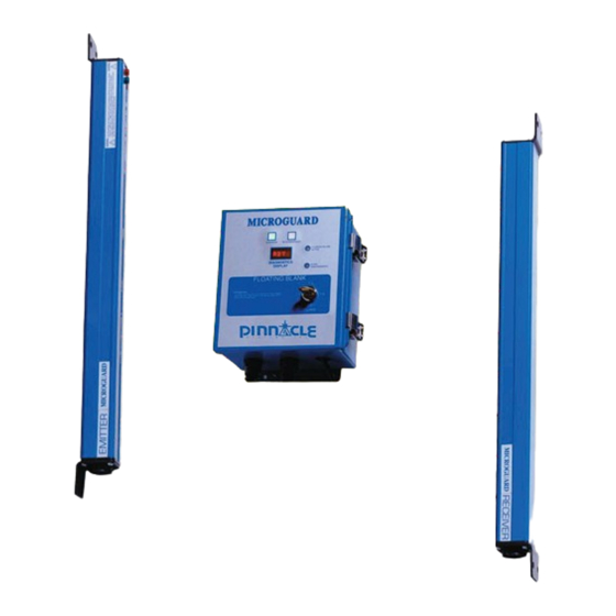
- Page 3 DIN-rail Controller Module Installation Manual Pinnacle Systems, Inc. 3715 Swenson Avenue St. Charles, IL 60174 P/N: 28-022r5-0 Customer Service: 630-443-8542 (CST) (Please have Model #, Serial #, and Software Rev # Available) Sales and Marketing: 800-569-7697 (EST) • • www.pinnaclesystems.com sales@pinnaclesystems.com...
- Page 4 We have designed our equipment to the very highest • The MicroGuard may not be able to safely stop performance and safety standards known to the current a press which has a faulty stopping mechanism.
- Page 5 The entire machine safety system must be tested at the start of every shift. Machine testing should include: (1) proper machine operation and stopping capability; and (2) verifi cation of proper installation and settings of all point of operation guards and devices before the operation is released for production.
-
Page 6: Table Of Contents
Table of Contents Introduction Theory of Operation ............................... iv The System ................................iv System Safety ................................ iv Safety Features ..............................iv Specifi cations ............................... 1 Standard Features Auxillary Relay Output ............................2 Emergency Stop Input ............................2 External Relay Check .............................2 Fault Relay Output ..............................2 Resettable Latching Relays ............................2 Remote Latching Reset ............................3 Safety Relay Outputs ..............................3... - Page 7 Table of Contents Dimensions Controller Module ..............................20 RSD Mounting Dimensions ...........................21 Accessories Cornering Mirrors ..............................22 Pedestal Mounting ..............................23 Swing-Arm Mounting Bracket ..........................23 Appendix A: Diagnostics & Troubleshooting Obstruction or Misalignment ..........................A-1 Error Conditions ..............................A-1 Status Display Messages ............................ A-2 Fault Display Messages ............................
- Page 8 Table of Contents Figures Figure 1: 4 Sided Guarding with Dual Stud Guard Brackets, TRM Mirrors and Model #8000 Pedestals ...9 Figure 2: Minimum Object Sensitivity and D(pf) ....................11 Figure 3: DIN-rail Controller Module Wiring Diagram ..................15 Figure 4: Internal Circuit Board View ........................16 Figure 5a: Swivel Bracket Dimensions ........................17 Figure 5b: Swivel Bracket Dimensions, pylon dimensions (by model), and additional cable information ...18 Figure 6:...
-
Page 9: Introduction
Introduction The MicroGuard DIN-rail Controller Module is an infrared and transistor receivers also spaced .5” or 1” apart. safety light curtain that is designed to the European The Controller Module contains diverse redundant IEC 61496 standard. IEC-61496 standard defines technology that includes two different microprocessors,... - Page 10 • Through the use of shielded cables, chokes, surge suppressers, and optically-coupled inputs, immunity to EMI/RFI fi elds is greatly increased. • The MicroGuard DIN-rail was designed to meet the European IEC 61496 standard parts 1 and 2 (part 2 requires use of optional 2 degree pylons), CSA, UL 1998, UL491, UL991, OSHA, ANSI, and RIA.
-
Page 11: Specifi Cations
Specifi cations DIN-rail Controller Module Input Power Temperature Range 24vdc +/- 20% (7 watts max) 0 to 50°C (up to 95% humidity, non-condensing) Input Fuse Dimensions 1 amp fast blow (pico size) 5.87” length X 2.95” width X Controller Module: 4.33”... -
Page 12: Standard Features
DIN-rail controller or Ground Terminal #3 on Resettable Latching Relays the Input/Output connector (the same input is used for Description: When power is applied to the MicroGuard the Latching Relay Reset). DIN-rail unit, it will stay in a “RED” condition until the Latching Reset Input is reset. -
Page 13: Remote Latching Reset
Standard Features Standard Features DIN-rail Controller Module DIN-rail Controller Module Remote Latching Reset Description: When the curtain is blocked, the unit will issue a “STOP” command and remain in this condition until the curtain is clear and the Latching Input is cycled. This feature must be enabled. Usage: Install a N.O. - Page 14 Standard Features DIN-rail Controller Module Page Intentionally Left Blank...
-
Page 15: Optional Features
Optional Features DIN-rail Controller Module Analog Output MODE Description Description: Ouput can be set up for either 0 to 10V or OFF/ –10V to 10V and proportional to the area blocked. You RESET Normal operation (no blanking) must specify the details of the output (see Installation Mode 2, but guard must be reset if unit is Procedures, “Figure 3: Controller Module Wiring penetrated. -
Page 16: Cincinnati Interface
Optional Features DIN-rail Controller Module LANK CONTINUED Table 2a: .5” Beam Spacing Pylons Place Auto Blank keyswitch into OFF/RESET position and remove any Minimum D(pf) Depth Max. Floating obstructions while aligning light curtain. Do not Display Object Penetration object size use Auto Blank until light curtain is correctly aligned Sensitivity, S Factor... -
Page 17: Guarding Mute-Out
To Activate Feature: Purchase sealed LED indicator You must power up the MicroGuard out of Mute-Out lights from the manufacturer or use your own. condition, any other condition will cause an error to occur and you will have to power down the guard to Usage: (see Installation Procedures, “Wiring”, and... -
Page 18: Installation Procedures
Press the FN1 button on top of the Controller Module to reset faults. 3) Determine if any part of the Microguard is to be directly subjected to either excessive shock System Check and/or vibration. If so, mount the subjected parts to your equipment using shock-mount devices 11) Check the curtain’s fi... -
Page 19: Aligning Pylons
Installation Procedures Installation Procedures DIN-rail Controller Module DIN-rail Controller Module GREEN indication. If you get a GREEN indication while the test piece is in the curtain’s fi eld of view, The diagnostics display will show the location of the this may be due to any of the following reasons: fi... -
Page 20: Operations
(see Optional Features, “Guarding Mute-Out”). . The display will show “AB” to Auto Blank Examine the MicroGuard on indicate that an object is programmed in and a daily basis to make sure that no one has moved the its size (in beams) is shown as the next digit. -
Page 21: Ansi Standard B11.19.2010
Installation Procedures Installation Procedures DIN-rail Controller Module DIN-rail Controller Module The following formula should be used when calculating ANSI Standard B11.19-2010 the safety distance: Formula for calculating safety distance Ds = K x (Ts + Tc + Tr + Tbm) + D(pf) of light curtains from hazardous point of operation. -
Page 22: Safeguarding With Mechanical Guards
Installation Procedures Installation Procedures DIN-rail Controller Module DIN-rail Controller Module Safeguarding with Mechanical Guards Light Curtain Test Procedure When a light system is used to protect the operator or Use a dowel rod (or similar object) with a diameter equal passerby from penetration, it must be mounted and to the M.O.S. -
Page 23: Wiring
Installation Procedures Installation Procedures DIN-rail Controller Module DIN-rail Controller Module Wiring Emitter Wire Colors Table 5 is a sample of how to wire the Controller Module. Certain features are not needed for many installations. Terminal Connector Read the sections in this manual describing each feature Shield (bare) to decide which feature(s) you may need. - Page 24 “Guarding Mute-Out”). • If you want remote indicators/diagnostics display, purchase the Remote Indicator option and follow the MicroGuard DIN-rail wiring diagram on the following page (see Appendix A: Diagnostics & Troubleshooting). • If you require Floating Blank or Auto Blank,...
-
Page 25: Figure 3: Din-Rail Controller Module Wiring Diagram
Installation Procedures Installation Procedures DIN-rail Controller Module DIN-rail Controller Module Figure 3: DIN-rail Controller Module Wiring Diagram (Combination of any feature below is allowable) If the Emergency Stop Input mushroom button is not used, the circuit still must be completed. -
Page 26: Controller Module Setup
Installation Procedures Installation Procedures DIN-rail Controller Module DIN-rail Controller Module Controller Module Setup Internal jumpers inside the Controller Module allow for FLASH Increases immunity to weld fl ash by slowing selection of pylon length (height of tower itself). Table down the curtain (doubles response time). 6 demonstrates how to set the internal jumpers if you CLOSE Activates Latching Relay Reset feature (see... -
Page 27: Swivel Bracket Dimensions
Dimensions DIN-rail Controller Module Pylon Dimensions Figure 5a: Swivel Bracket Dimensions... -
Page 28: Pylon Dimensions (By Model) (Swivel)
Dimensions DIN-rail Controller Module Pylon Dimensions Figure 5b: Swivel Bracket Dimensions, pylon dimensions (by model), and additional cable information... -
Page 29: Fixed Bracket Dimensions
Dimensions DIN-rail Controller Module Figure 6: Fixed Bracket Dimensions, pylon dimensions (by model), and additional cable information... -
Page 30: Dimensions
Dimensions DIN-rail Controller Module Controller Module The Controller Module can be either DIN-rail mounted or screwed down. Be sure to allow space for wiring to top of box (both sides). Enclosure: Gray polycarbonate with clear cover. Provides IP40, UL94V-1 Enclosure Dimensions: 5.87” (149 mm) length x 4.33” (110 mm) depth x 2.95”... -
Page 31: Rsd Mounting Dimensions
Dimensions DIN-rail Controller Module Remote Status Display (RSD)™ Figure 8: RSD Mounting Dimensions Figure 9: RSD with Floating Blank or Auto Blank Mounting Dimensions... -
Page 32: Accessories
Accessories DIN-rail Controller Module Cornering Mirrors Through the use of cornering mirrors, multiple sides or Mirrors are surface coated. work envelopes can be guarded which enhance safety Wipe surface using only a damp, clean, soft 100% and down-time related to mechanical and electrical cotton cloth. -
Page 33: Pedestal Mounting
DIN-rail Controller Module Pedestal Mounting The heavy duty, all-welded steel pedestal fl oor mounts can be used for mounting either the MicroGuard Metal Figure 11: Pedestal Dimensions Box or DIN-rail Controller Module or cornering mirrors. Sliding mounts on the pedestal are universal in design and are supplied standard. -
Page 34: Appendix A: Diagnostics & Troubleshooting
Appendix “A” Diagnostics & Troubleshooting NOTE: For all guards with a USB connector NOTE: For all guards with socket on the inside of the door (after 6/2012) microprocessors (prior to 6/2012) Obstruction or Misalignment Obstruction or Misalignment When the curtain is obstructed or misaligned, the display will When the curtain is obstructed or misaligned, the display present four numbers to indicate location of obstruction or will present four numbers to indicate location of obstruction... -
Page 35: Status Display Messages
Appendix “A” Diagnostics & Troubleshooting The Diagnostics Display has two modes of operation: Mute-Out Status and Fault. If a fault occurs, the display will scroll MUTE Guard has gone into by-pass mode the fault message until the “FN1” fault reset button is pushed, even if the cause of the fault is corrected and/ Cincinnati Interface or you reset the power. - Page 36 Appendix “A” Diagnostics & Troubleshooting External infrared source detected xxy No ACK from memory The curtain (during a blocked condition) detected No signal received from memory chips. Faulty infrared light from another source. Check for other memory chip. curtains and make sure the Receiver pylon is not No clock line detected pointing in their direction.
- Page 37 Appendix “A” Diagnostics & Troubleshooting SBLK SLAVE microprocessor detected blockage when the MASTER did not. Some of the receiver signals are so weak that the leading edge of the pulse is missed by the SLAVE but the trailing edge is not missed by the MASTER.
-
Page 38: Appendix B: Regulations And Guidelines
Appendix “B” Regulations and Guidelines OSHA Regulations auxiliary equipment, and safeguards are in a safe operating condition and adjustment. 1910.217 (C) (3) (iii) The employer shall maintain records of Safeguarding the Point of Operation these inspections and maintenance work (iii) A presence sensing point of operation device shall performed. -
Page 39: Safety Guidelines And Management
Appendix “B” Regulations and Guidelines “...control circuits shall incorporate features to minimize should be assigned to work on or with any the possibility of an unintended stroke in the event of machine. the failure of the control component to function properly, 9. -
Page 40: Power Press Guarding
Appendix “B” Regulations and Guidelines Power Press Guarding Safety Enforcement 1. Press manufacturers do not know and cannot foresee the magnitude of potential In order to have an effective safety program, applications of power presses. Therefore, management at all levels must enforce every safety only the press user can determine the type of rule and regulation. -
Page 41: Appendix C: Replacement Parts
Appendix “C” Replacement Parts Pylons Figure 11: Pylon Replacement Part Numbers 27-019 Yellow lense !!NOTE!! You must provide Model #, Serial # and software revision # to obtain the correct part revision or sub-assembly revision. An individual Part# may have been revised since your unit was purchased. -
Page 42: Appendix D: Usb Diagnostic Codes
Appendix “D” USB Diagnostic Codes Model MG or DR USB Diagnostic Codes: Master Controls USB port You must install the Silabs CP210x USB driver on your windows PC. Check your Device Manager for Silabs COM port#. You read the port at 115200 Baud 8N1 Char Description B or b... - Page 43 SEMF0P <CR> 10 lines of EEPROM memory <CR> GA0024m (for a 24 beam length guard) Blocked Beam pattern display: If you transmit the ASCII character ‘B’ via the USB port, the Microguard will return a string of ASCII charac- ter 1’s and 0’s based on the beam blockage.
- Page 44 NOTES Questions? Email the Sales Department at sales@pinnaclesystems.com or our Engineers at service@pinnaclesystems.com.
- Page 45 NOTES Questions? Email the Sales Department at sales@pinnaclesystems.com or our Engineers at service@pinnaclesystems.com.
- Page 46 NOTES Questions? Email the Sales Department at sales@pinnaclesystems.com or our Engineers at service@pinnaclesystems.com.
- Page 47 CHANGE IN SPECIFICATIONS DISCLAIMER Pinnacle Systems, Inc. does not assume liability for the Product specifi cations and accessories may be changed contents of this publication or the use of any products at any time based on improvements and other reasons.
- Page 48 Direct Number: 412-262-3950 equipment not manufactured, installed, secured or Fax: 412-262-4055 maintained by Pinnacle Systems, Inc. Canada We cannot and do not accept responsibility for any overall system performance when factors, such as Pinnacle Systems, Inc.
Need help?
Do you have a question about the microguard and is the answer not in the manual?
Questions and answers