
Related Manuals for Pinnacle microGUARD DIN-rail Controller Module

Summary of Contents for Pinnacle microGUARD DIN-rail Controller Module
- Page 1 • ® m1croGUARD Installation Manual for the DIN-rail Controller Module SAFETY INSTRUCTIONS AWARNING Read and fully understand this manual. Failure to do so could result in death or serious injury.
- Page 2 ADANGER DANGER indicates a hazardous situation which, avoided, will result in death or serious injury. - - - - - - - - WARNING indicates a hazardous situation which, avoided, could result in death or serious injury. ACA TIO CAUTION indicates a hazardous situation which, avoided, could result in minor or moderate injury.
- Page 3 DIN-rail Controller Module Installation Manual Pinnacle Systems, Inc. 1510 Hubbard Ave. Batavia, IL 60510 USA PIN: 28-022r5-5 Customer Service: 630-443-8542 (CST) (Please have Model#, Serial#, and Software Rev #Available) Sales and Marketing: 800-569-7697 (EST) www.pinnaclesystems.com • sales@pinnaclesystems.com • service@pinnaclesystems.com...
- Page 4 Proper Usage and Limitations procedures have been and will be followed. • All procedures in this manual must be followed. A.WAR I G The information disclosed herein The manufacturer cannot take responsibility for includes proprietary rights of the manufacturer. Neither operation if all procedures and warnings in this this document nor the information disclosed herein shall manual are not followed.
- Page 5 £WAR I The entire machine safe ty system must be tested at the start of every shift. Machine testing should include: (1) proper machine operation and stopping capability; and (2) verification of proper installation and settings of all p oint of operation guards and devices before the operation is released for production.
-
Page 6: Table Of Contents
Table of Contents Introduction Theory o f Operation ............................... iv The System ................................iv System Sa f ety ................................ iv Sa f ety Features ..............................iv Specifications ............................... 1 Standard Features Auxiliary Relay Output ............................2 Emergency Stop Input ............................2 External Relay Check ............................. - Page 7 Table of Contents Dimensions Controller Mo dule ..............................20 RSD Mounting Dimensi ons ........................... 21 Accessories Cornering Mirrors ..............................22 Pedes tal Mounting ..............................23 Swing-Arm Mounting Bracket ..........................23 Appendix A: Diagnostics & Troubleshooting Obstructi on or Misalignment ..........................A-1 Error Condi tions ..............................
- Page 8 Table of Contents Figures Figure 1: 4 Sided Guarding with Dual Stud Guard Brackets, TRM Mirrors and Model #8000 Pedestals ... 9 Figure Minimum Object Sensitivity (S) and D(pf) ..................11 Figure DIN-rail Controller Module Wiring Diagram ..................15 Figure 4: Internal Circuit Board View ........................
-
Page 9: Introduction
Introduction The MicroGuard DIN-rail Controller Module is an infrared and transistor receivers also spaced .5" or 1" apart. safety light curtain that is designed to the European The Controller Module contains diverse redundant IEC 61496 standard. IEC-61496 standard defines technology that includes two different microprocessors,... - Page 10 Introduction problems from occurring simultaneously in both redundant circuits. • Force-guided relays allows dry relay contacts to be monitored for contact welding and/or circuit failure. • Watchdog timers on both computers and both safety relays assures that a system lock-up will automatically drop out the safety relays.
-
Page 11: Specifications
Specifications DIN-rail Controller Module Input Power Temperature Range 24vdc 20% (7 watts max) ° 0 to 50 C (up to 95% humidity, non-condensing) Input Fuse Dimensions 1 amp fast blow (pico size) Controller Module: 5.87" length X 2.95" width X 4.33"... -
Page 12: Standard Features
SAFETY Standard Features INSTRUCTIONS DIN-rail Controller Module Auxiliary Relay Output in a "RED" condition. The monitored external contacts must close and the primary contacts must open in a Description: Use this relay for horns, lights, and signals "RED" condition within 250mSec's or an error will occur. back to PL C's. -
Page 13: Remote Latching Reset
SAFETY Standard Features INSTRUCTIONS DIN-rail Controller Module Remote Latching Reset Description: When the curtain is blocked, the unit will issue a "STOP " com mand and remain in this condition until the curtain is clear and the Latching Input is c ycled. T his feature must be enabled. Usage: Install a N.O. - Page 14 Page Intentionally Left Blank...
-
Page 15: Optional Features
Optional Features SAFETY DIN-rail Controller Modu le INSTRU CTIONS Analog Output MODE Description Description: Ouput can be set up for either Oto 1 0V or OFF/ -1 0V to 10V and proportional to the area blocked. You RESETNormal operation (no blanking) must specify the details of the output (see Inst allation Mode 2, but guard must be reset if uni t is Procedures, "Fig ure 3: Controller Modu le Wiring... -
Page 16: Cincinnati Interface
Optional Features SAFETY DIN-rail Controller Module INSTRUCTIONS (Auro BLANK CONTINUED) A.CAUTION Table 2a: .5" Beam Spacing Pylons Place Auto Blank keyswitch into OFF/RE SET position and remove any Minimum D(pf) Depth Max. Floating obstructions while aligning light curtain. Do not Object Display Penetration... -
Page 17: Guarding Mute-Out
Optional Features SAFETY DIN-rail Controller Module INSTRUCTIONS (FLOATING BLANK CONTINUED) ACA UTIO N NOTICE P l a c e F l oa t i n g B l a n k keyswitch into 0.5'' position and remove an y To by-pass this feature, jumper obstructions while aligning light curtain. -
Page 18: Installation Procedures
SAFETY Installation Procedures INSTRUCTIONS DIN-rail Controller Module £WARNING CAUTION The entire machine safety Shock mount the pylons if they are system must be tested at the start of every shift. to be directly mounted onto a high vibration machine. Do Machine testing should include: (1) proper not lock down the pylons or mirrors until proper alignment machine operation and stopping capability;... -
Page 19: Aligning Pylons
SAFETY Installation Procedures INSTRUCTIONS DIN-rail Controller Module £WARNING GREEN indication. If you get a GREEN indication while the test piece is in the curtain's field of view, The diagnostics display will show the location of the this may be due to any of the following reasons: first blocked beam. -
Page 20: Operations
SAFETY Installation Procedures INSTRUCTIONS DIN-rail Controller Module Operations display will show "CINN" during the up stroke (see Optional Features, "Guarding Mut e-OufJ. ACAUTION 6) Auto Blank. The display will show "A B" to Examine the MicroGuard on indicate that an object is programmed in and a daily basis to make sure that no one has moved the its size (in beams) is shown as the next digit. -
Page 21: Ansi Standard B11.19.2010
SAFETY Installation Procedures INSTRUCTIONS DIN-rail Controller Module The following formula should be used when calculating ANSI Standard B11.19-2010 the safety distance: Formula for calculating safety distance K x (Ts+ Tc+ Tr+ Tbm) + D(pf) of light curtains from hazardous point of operation. -
Page 22: Safeguarding With Mechanical Guards
SAFETY Installation Procedures INSTRUCTIONS DIN-rail Controller Module Safeguarding with Mechanical Guards Light Curtain Test Procedure When a light system is used to protect the operator or Use a dowel rod (or similar object) with a diameter equal passerby from penetration, it must be mounted and to the M.O.S. -
Page 23: Wiring
SAFETY Installation Procedures INSTRUCTIONS DIN-rail Controller Module Wiring Emitter Wire Colors Table 5 is a sample of how to wire the Controller Module. Certa in features are not needed for ma ny installations. Terminal Connector Read the sections in this manual describing ea ch feature Shield (bare) to decide which feature(s ) you may need. - Page 24 SAFETY Installation Procedures INSTRUCTIONS DIN-rail Controller Module Figure 3 is a diagram representing only one wiring method. If hazardous machine requires two separate "stop" circuits, you must remove the jumper between terminal 5 & 6 of the POWER / RELAYS strip and use terminal 4 & 5 for "stop" circuit #1 and terminal 6 &...
-
Page 25: Figure 3: Din-Rail Controller Module Wiring Diagram
SAFETY Installation Procedures INSTRUCTIONS DIN-rail Controller Module (Combination of any feature below is allowable) Figure 3: DIN-rail Controller Module Wiring Diagram (N.O. are Held Closed, N.C. are Held Open) To Interface to OB-9. straight Remote wire, 1 to 1 Dlagnolk:s 01 ,p lay DeviceNet mi c roGUARct... -
Page 26: Controller Module Setup
■ SAFETY Installation Procedures INSTRUCTIONS DIN-rail Controller Module Controller Module Setup Internal jumpers inside the Controller Module allow f or Increases immunity to weld f lash by slowing FLASH selection o f pylon length (height o f tower itself). Table down the curtain (doubles response time). -
Page 27: Swivel Bracket Dimensions
"11 t- 2,2500 7 RE\IISIOS ZONE I REV DATE 0£SCRIPTION < NOTEl: 21-032 \./ITH HOLES □ � 1.5000 21-033 \./ITH UT HOLES " � ¢1.3750 3" (4) #6 COUNTERSUNK (4) PEM 6-32 STUDS NOTEl :::::s HOLES (0.15 DIA) !!!. 0.1500 :::::s l¢2.2500 - ---- + -- r=._ - --,-- r------ -------r t... -
Page 28: Pylon Dimensions (By Model) (Swivel)
-· 10·z "11 C: I �o CD �. -· :::s (/)a RFoOSIONS .. 0 :; . a Extrusion• 1.45'(3.68cM) Squore Lights on O.TE N'PROYE1 ZONE I REV 0£SCIOPT eMltter Dlstonce froM first to lost beoM <= only Mounting hole distonce (I) (I) :::s Length of extrusion... -
Page 29: Fixed Bracket Dimensions
---------------------------------------------------------@ , _ 1...,1 RE\'ISIO Distance from first to last beam "11 °"TE Mounting hole distance ><' AP9R!MI) 2.84 �m Length of extrusion Tol. +/- 0.10"(.25cm) Overall length I:» " (") '---I... L 8kt A (in) A(cm) B (in) B(cm) C(in) C(cm) (in) -
Page 30: Dimensions
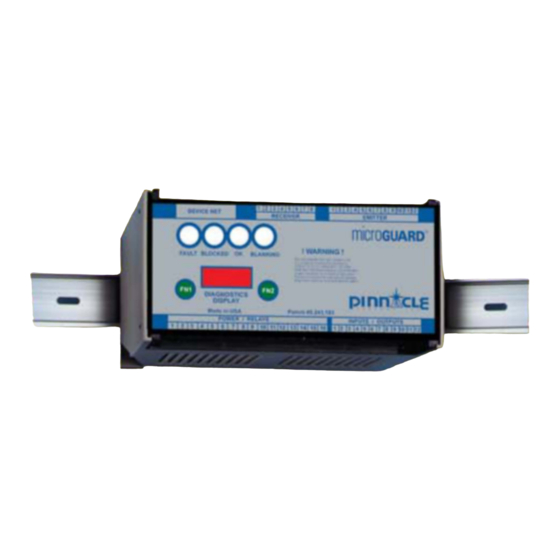
Dimensions DIN-rail Controller Module Controller Module The Controller Module can be either DIN-rail mounted or screwed down. Be sure to allow space for wiring to top of box (both sides). Enclosure : Gray polycarbonate with clear cover. Provides IP40, UL94V-1 Enclosure Dimensions: 5.87"... -
Page 31: Rsd Mounting Dimensi Ons
Dimensions DIN-rail Controller Module Remote Status Display ™ (RSD) Figure 8: RSD Mounting Dimensions r nt v,ew s1ol!? view 3 ODO "0000 70110--- ---3 B �6-32 x 75' per: ., ud Ct,· Ot..l w >< ·-l/4'h .05 • tflk Figure 9: RSD with Floating Blank or Auto Blank Mounting Dimensions ,,_ _________________ _________________ __ .062' "thk... -
Page 32: Accessories
Accessories DIN-rail Controller Module Cornering Mirrors NOTICE Through the use o f cornering mirrors, multiple sides or Mirrors are surface coated. work envelopes can be guarded which enhance safety Wipe surface using only a damp, clean, so f t 100% and down-time related to mechanical and electrical cotton cloth. -
Page 33: Pedestal Mounting
Accessories DIN-rail Controller Module Pedestal Mounting The heavy duty, all-welded steel pedestal floor mounts can be used for mounting either the MicroGuard Metal Figure 11: Pedestal Dimensions Box or DIN-rail Controller Module or cornering mirrors. Sliding mounts on the pedestal are universal in design and are supplied standard. -
Page 34: Appendix A: Diagnostics & Troubleshooting
Appendix "A" Diagnostics & Troubleshooting NOTE: For all guards with a USB connector NOTE: For all guards with socket on the inside of the door (after 6/2012) microprocessors (prior to 6/2012) Obstruction or Misalignment Obstruction or Misalignment When the curtain is obstructed or misaligned, the display will When the curtain is obstructed or misaligned, the display present f our numbers to indicate location o f obstruction or will present four numbers to indicate location o f obstruction... -
Page 35: Status Display Messages
"N' Appendix Diagnostics & Troubleshooting The Diagnostics Display has two modes of operation: Mute-Out Status and Fault. If a fault occurs, the display will scroll MUTE Guard has gone into by-pass mode the fault message until the "FN1" fault reset button is pushed, even if the cause of the fault is corrected and/ Cincinnati Interface or you reset the power. - Page 36 Appendix "A" Diagnostics & Troubleshooting External infrared source detected xxy No ACK from memory The curtain (during a blocked condition) detected No signal received from memory chips. Faulty infrared light from another source. Check for other memory chip. curtains and make sure the Receiver pylon is not No clock line detected pointing in their direction.
- Page 37 "N' Appendix Diagnostics & Troubleshooting SBLK SLAVE microprocessor detected blockage when the MASTER did not. Some of the receiver signals are so weak that the leading edge of the pulse is missed by the SLAVE but the trailing edge is not missed by the MASTER.
-
Page 38: Appendix B: Regulations And Guidelines
SAFETY Appendix "B" INSTRUCTIONS Regulations and Guidelines OSHA Regulations auxiliary equipment, and safeguards are in a safe operating condition and adjustment. 1910.217 (C) (3) (iii) The employer shall maintain records of Safeguarding the Point of Operation these inspections and maintenance work (iii) A presence sensing point of operation device shall performed. -
Page 39: Safety Guidelines And Mana Gement
SAFETY Appendix "B" INSTRUCTIONS Regulations and Guidelines " ... control circuits shall incorporate features to minimize should be assigned to work on or with any the possibility of an unintended stroke in the event of machine. the failure of the control component to function properly, 9. -
Page 40: Power Press Guarding
SAFETY Appendix "B" INSTRUCTIONS Regulations and Guidelines Power Press Guarding Safety Enforcement Press manufacturers do not know and cannot foresee the magnitude of potential In order to have an effecti ve safety prog ram, applications of power presses. Therefore, management at all levels must enforce every safety only the press user can determine the type of rule and regulation. -
Page 41: Appendix C: Replacement Parts
Appendix "C" Replacement Parts Pylons Figure 11: Pylon Replacement Part Numbers 21--012 Upper 21-007 Bracket 52-128 8" Slave Receiver (1/2" beam) Gasket 52--078 8" Slave Emitter (1/2" beam) 52-141 8" Slave Receiver (CE 112· beam) 52-150 8" Slave Emitter (CE 1/2"... -
Page 42: Appendix D: Usb Diagnostic Codes
Appendix "D" USB Diagnostic Codes Model MG or DR USB Diagnostic Codes: Master Controls USB port NOTICE You must install the Si labs CP21 Ox USB driver on your windows PC. Check your Device Manager for Silabs COM port#. You read the port at 115200 Baud 8N1 Char Description B or b... - Page 43 Appendix "D" USB Diagnostic Codes Model MG or DR USB Diagnostic Codes: Master Controls USB port Cont. NOTICE You must install the Si labs CP210x USB driver on your windows PC. Check your Device Manager for Silabs COM port#. You read the port at 115200 Baud 8N1 Fault Codes: in HEX code Mute-out switch fault Open LED in emitter pylon...
- Page 44 NOTES Questions? Email the Sales Department at sales@pinnaclesystems.com or our Engineers at service@pinnaclesystems.com.
- Page 45 NOTES Questi ons? Emai l the Sales Department at sales@pinnaclesystems.com or our Engineers at servi ce@pinnaclesystems.com.
- Page 46 NOTES Questions? Email the Sales Department at sales@pinnaclesystems.com or our Engineers at service@pinnaclesystems.com.
- Page 47 CHANGE IN SPECIFICATIONS DISCLAIMER Pinnacle Systems, Inc. does not assume liability for the Product specifications and accessories may be changed contents of this publication or the use of any products at any time based on improvements and other reasons.
- Page 48 Number: 412-262-3950 equipment not manufa ctured, installed, secured or Fax: 412-262-4055 maintained by Pinnacle S ystems, Inc. United States We cannot and do not a ccept responsibility for any o verall system performance when factors, such as Pinnacle Systems, Inc.
Need help?
Do you have a question about the microGUARD DIN-rail Controller Module and is the answer not in the manual?
Questions and answers