
Pinnacle microguard Manuals
Manuals and User Guides for Pinnacle microguard. We have 2 Pinnacle microguard manuals available for free PDF download: Installation Manual
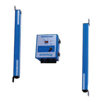
Pinnacle microguard Installation Manual (48 pages)
Metal Box Controller Module
Brand: Pinnacle
|
Category: Security Sensors
|
Size: 3 MB
Table of Contents
Advertisement

Pinnacle microguard Installation Manual (48 pages)
din-rail controller module
Brand: Pinnacle
|
Category: Controller
|
Size: 1 MB